Project 2 Thermal modeling of battery pack
different types of block used and their parameters.
-Battery(table based) - using intrumented and thermal port , to define the SOC and temperature of the battery.
- Build up signal- To define how the vechile is loaded from which the charge discharge cycle of battery can be justified.
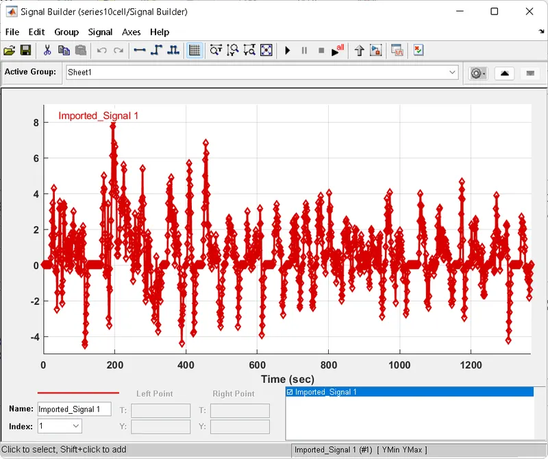
-Controlled current source: Acts as an input to the batteries.The drive cycle is connected to the batteries with the help of controlled current source.
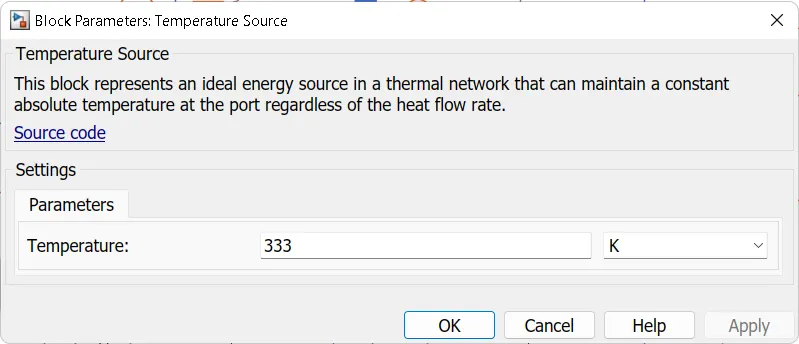
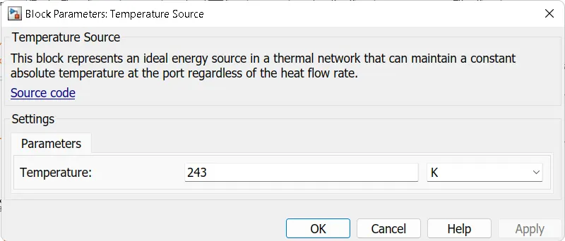
-Temperature source- represents the ambient temp . In this project we are considering different temp. range in kelving.
-Thermal and electrical reference:- every thermal and electrical reference should be grounded off to allow the excess current and temp. to floe into the ground.
-Convective heat transfer : Depending upon the area of contact , the thermal management of the modules increases or decreases.
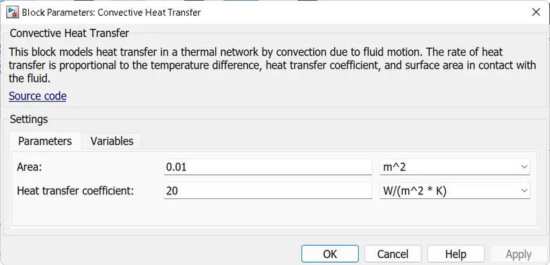
-Temperature sensor: To sense the temperature of the individual cells.
%10 cell series lithium ion battery model
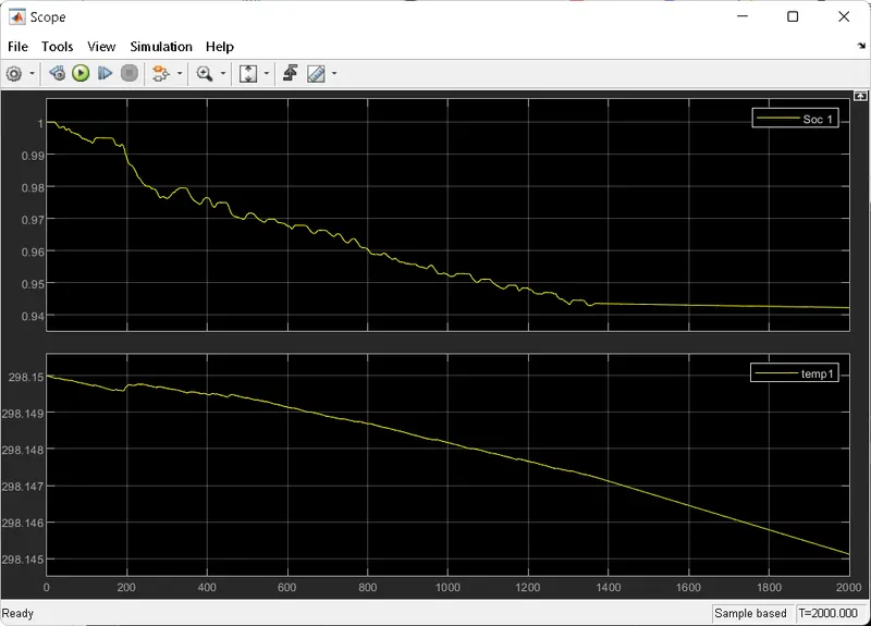
Case 1 : Ambient Temperature is considerd as :293.15K 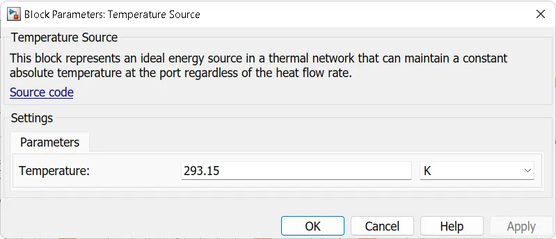
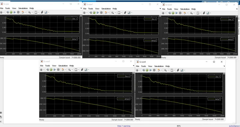
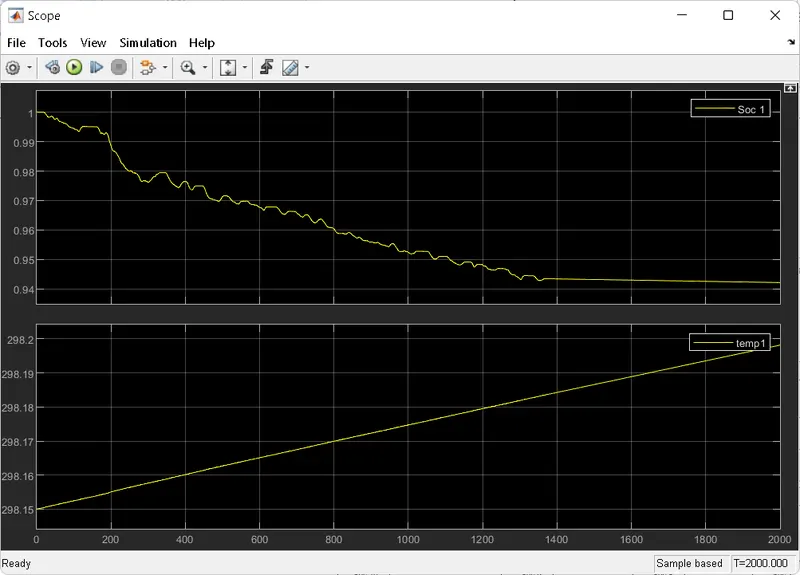
Case 2: Ambient Temp.333 k
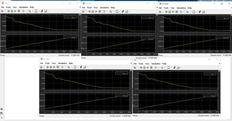
Case 3: Ambient temp. as 243K
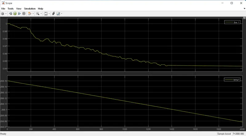
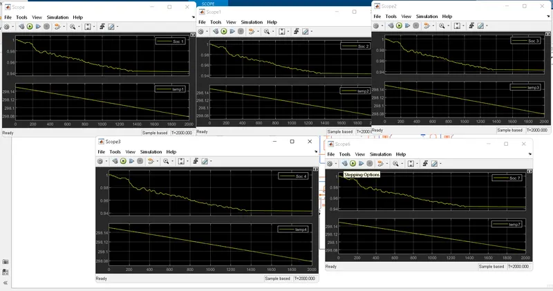
Compairing all the three cases we can conclude that temperature gradually increases in case of case 2 having ambient temp of 333k and that in case of cooler region i.e temp of243K temp. of battery decreases with time.
In the above cases we have not changed any of the special parametrs of the system. Keeping the convective heat transfer coeff same in all the cases the result is tabulated .
Working of model:
-Initially after the configuration of the battery block , same copied blocks are arranged in the series manner so as to maintain the constant current flow through it.
-The negative terminal of 1st battery and positive terminal of 18th or last battery are connected with help of controll current source which is then connected to drive cycle.
-Each battery have their own temperature sensor, so as to limit the battery temperature from exceding certail value.
-If any of the batterys faults out, the whole circuid is needed to replace or else short circuited.
-The scope shows individual measurements of each cells.
Model:
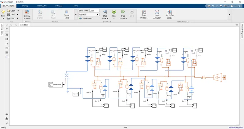
%Using generic battery model: 10Series.
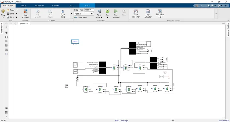
The above figure shows the model diagram using generic battery system.
It consists of batteries, Bus selector, scope,square wave builder, ps constant block, solver,and powergui.
Batteries : Batteries are configured in the following manner as to get the temperatue , capacity and age of the battery . Below Figure gives detail explanation .
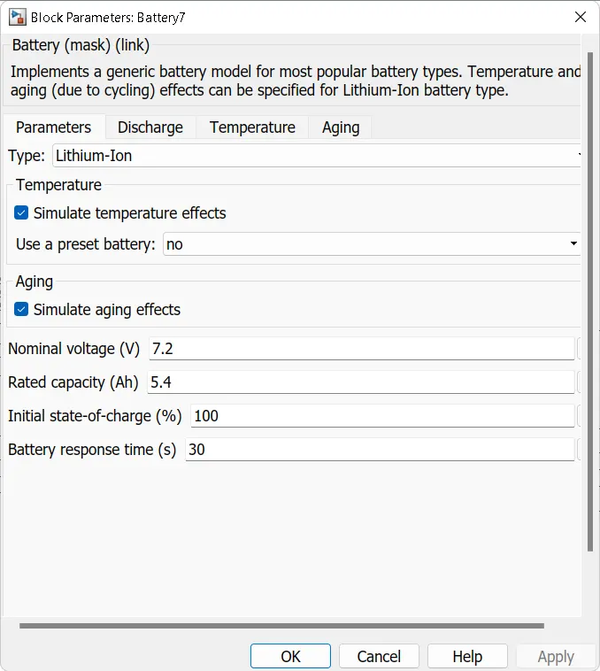
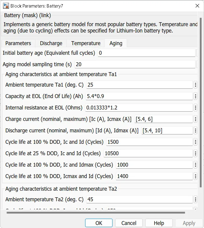
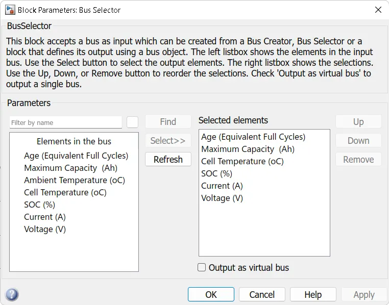
Bus selector: The signals inputs comming out of batteries are automatically selected with the help of bus. The bus then transfers the signal to scope.
scope: It show the signals that are passed through bus selector.
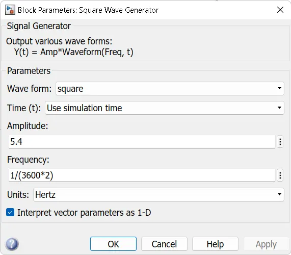
square wave builder: Represents the load condition. Amplitude is set to peak current.
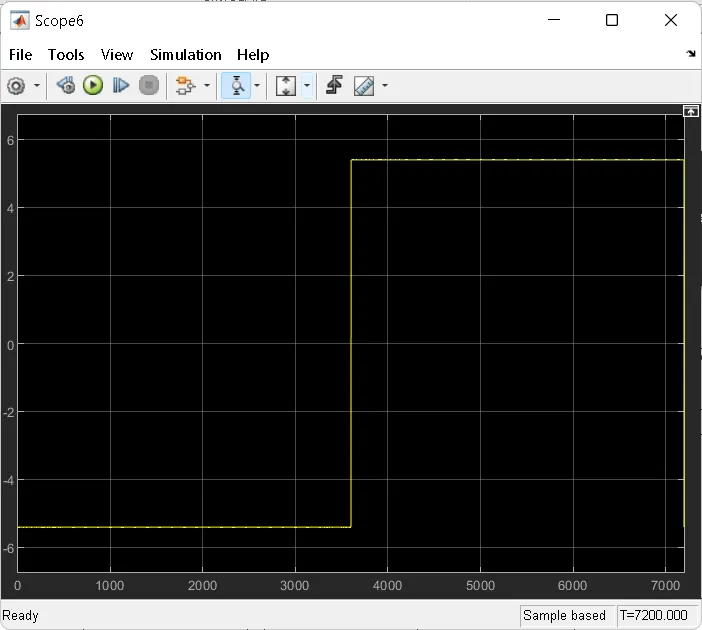
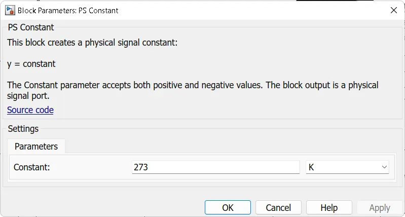
ps constant block: Similar to the conctant block , It gives the ambient temperature that has been set.
solver: To solve the complicated problems easily we use solver.
powergui: The block that powers the whole system is power gui.
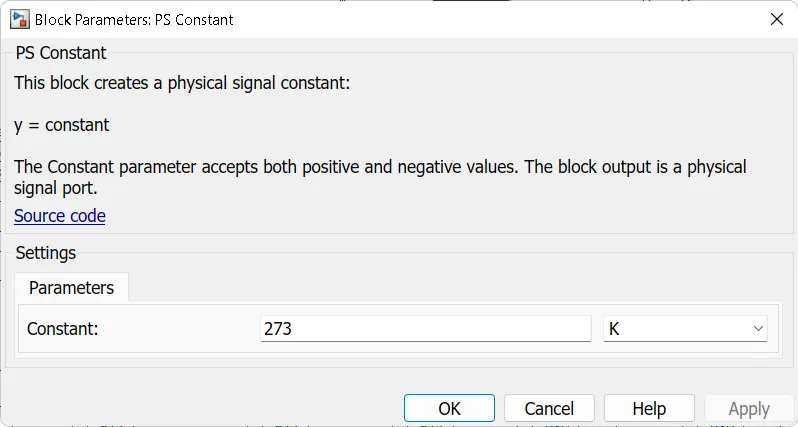
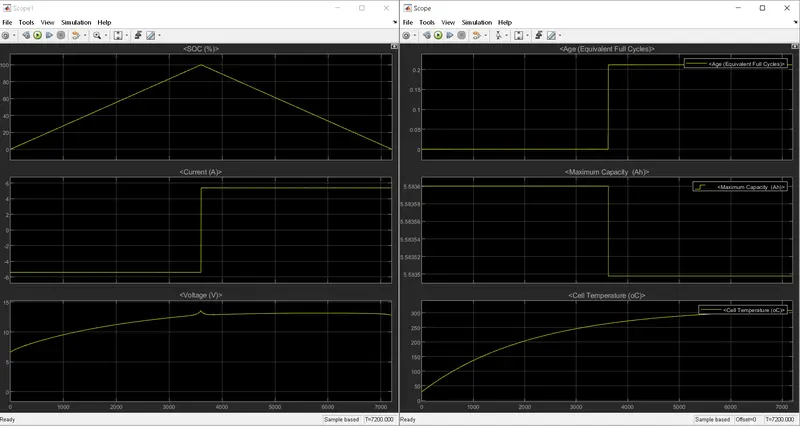
Case 1: considering temp as 273k
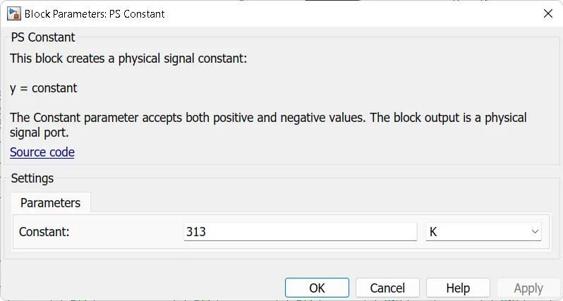
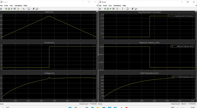
Case 2: considering temp as 313k .
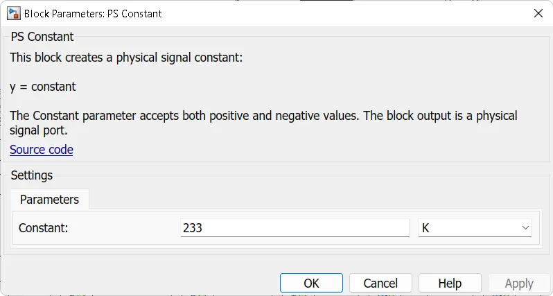
Case 3: considering temp as 233k .
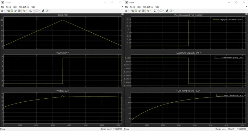
From the above experimental results it can be seen that , the performance of battery increases when the battery is kept in the cooled state. The atmosphere temperature affects the battery life, capacity and aging factor drastically.
Depending upon the atmospheric condition as temperature of battery increases, faster will be the aging of battery , similarly the capacity of battery decreases with decrease in state of charge.From the above 3 cases it easier to annalyse and maintain the battery temperatures in specified limits so as to get maximum or optimum performance of the battery.