Project 2
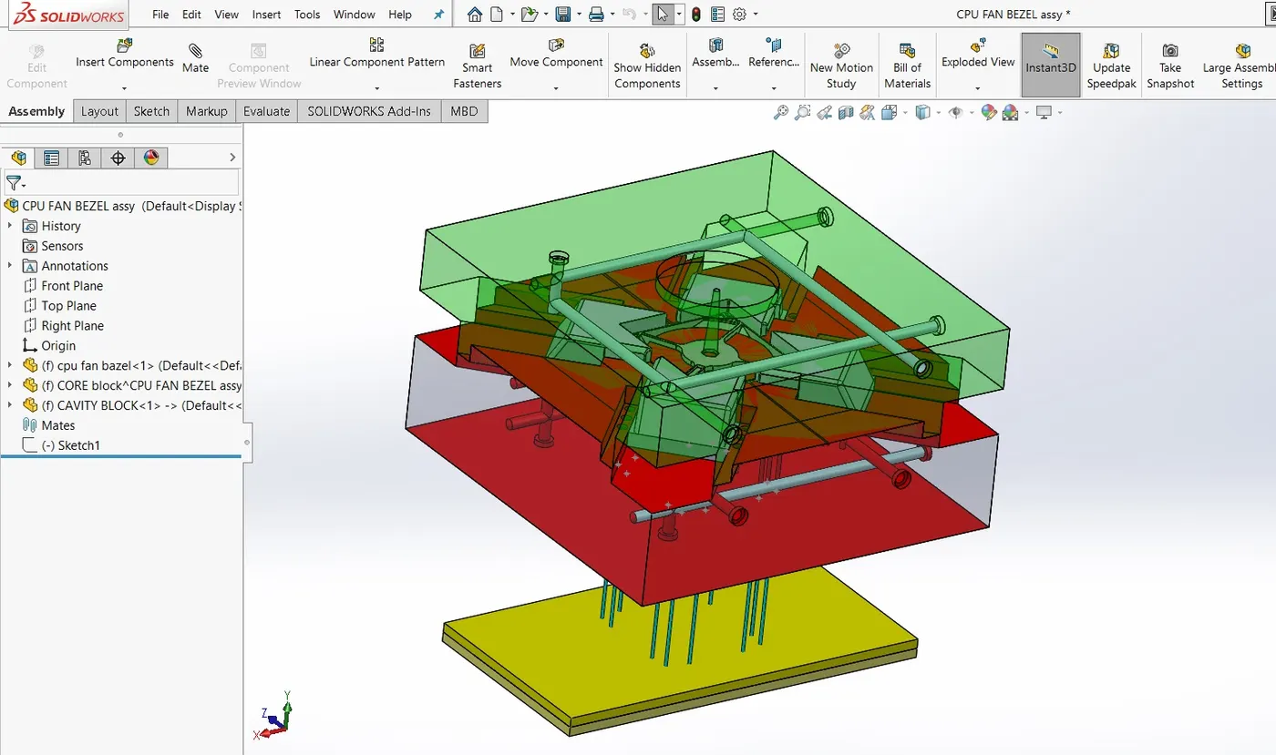
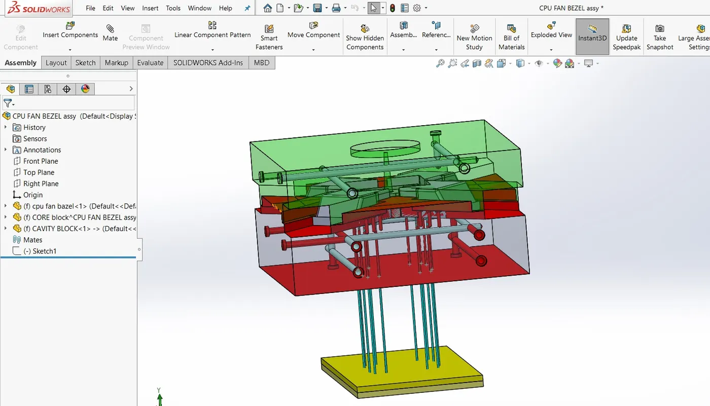
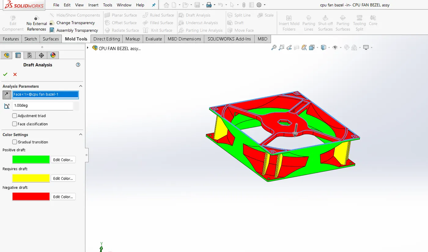
--> DRaft Analysis:
Scaling: The value of shrinkage is 0.6%, therefore scaling of 1.06factor is considered.
Parting Line: The line where core & cavity block seperates each other is called parting line.
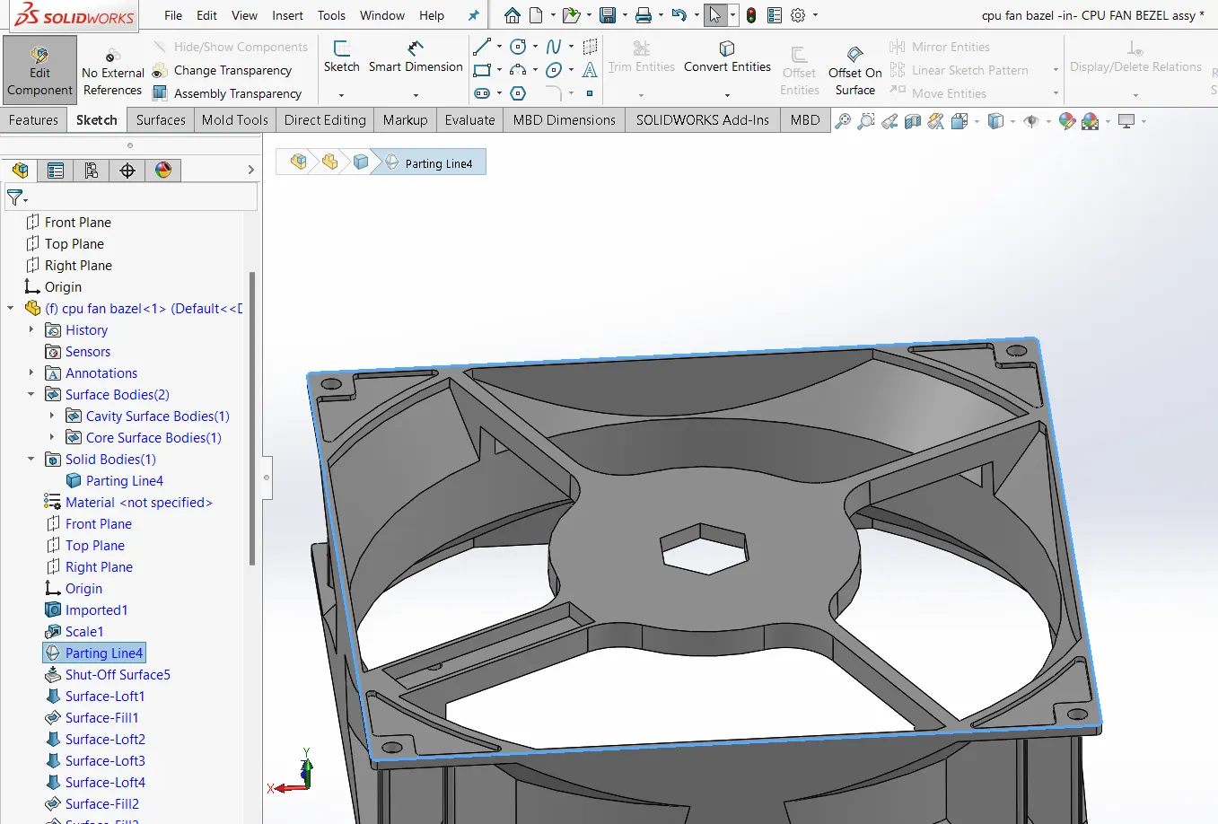
Shut off surfaces: The open feature in the part are to be shut off so that core & cavity block seperates each other.
Surface loaft commant is used to create some shut off faces.
Core & cavity surfaces: AFter when mold is seperated into core & cavity blocks seperate surfaces are created using ruled surface Normal to surface command & the knitted with respective core caviity surfaces.
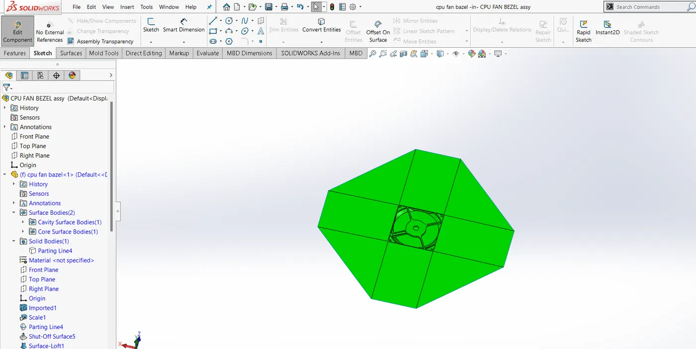
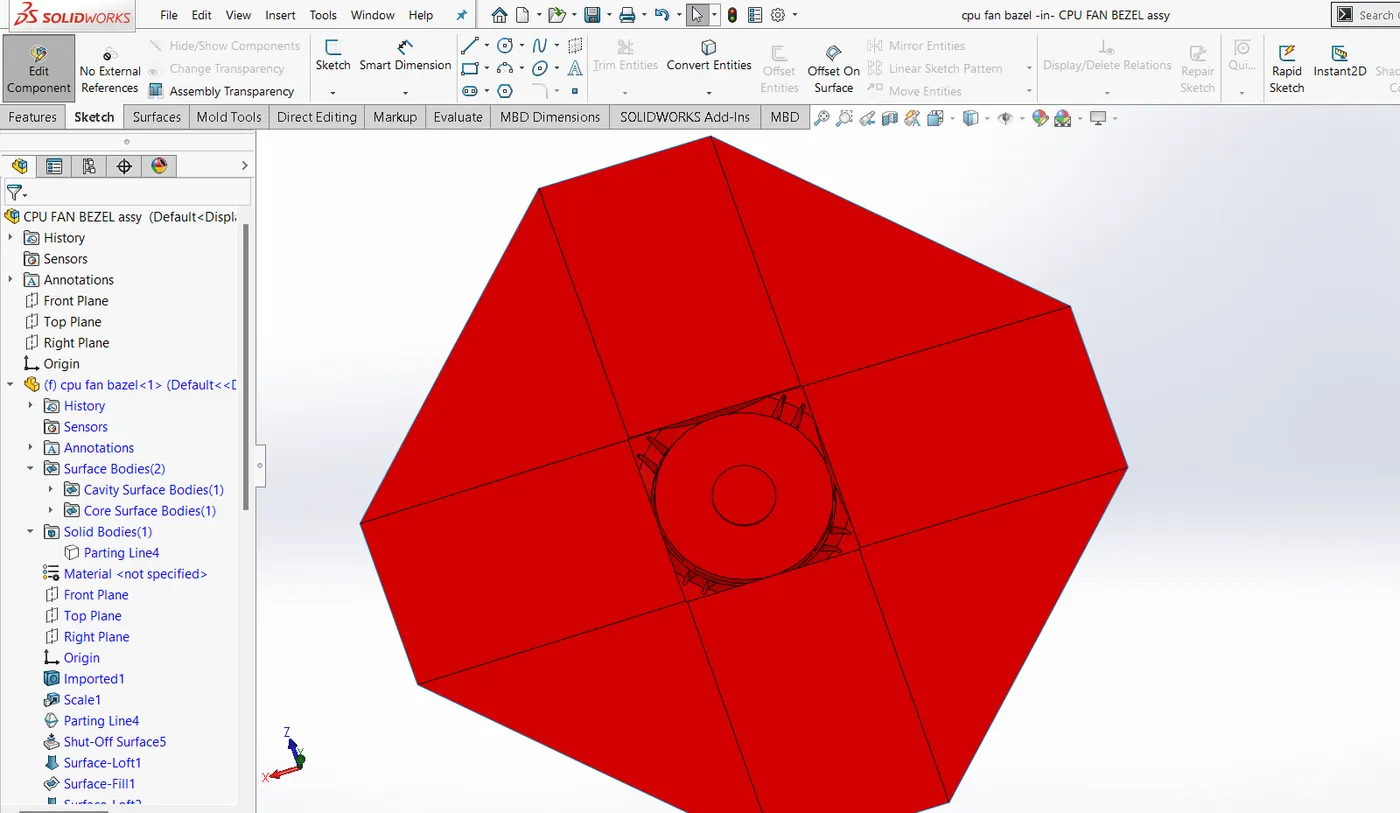
Core & cavity blocks: Since the surfaces are 3D in naturre,2 types of box are created. The inner box resembles the actual 3D profile of feature where as the outer box is 2D in nature.
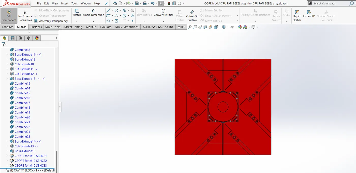
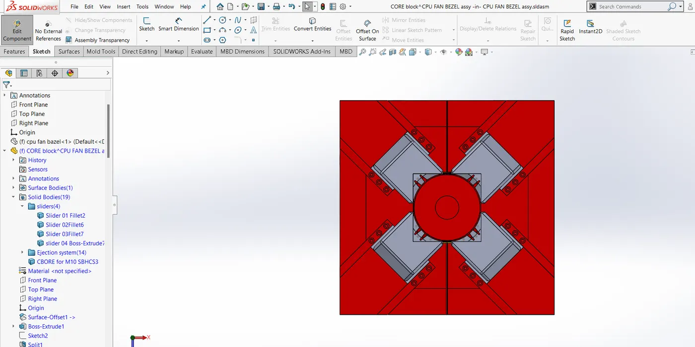
SLiders: Sliders are created where we have undercuts & it cannot be cleared using the main tooling axis.
Since the 4 edges with respective profile is not cleared using the main tooling axis, 4 sliders are to be created.
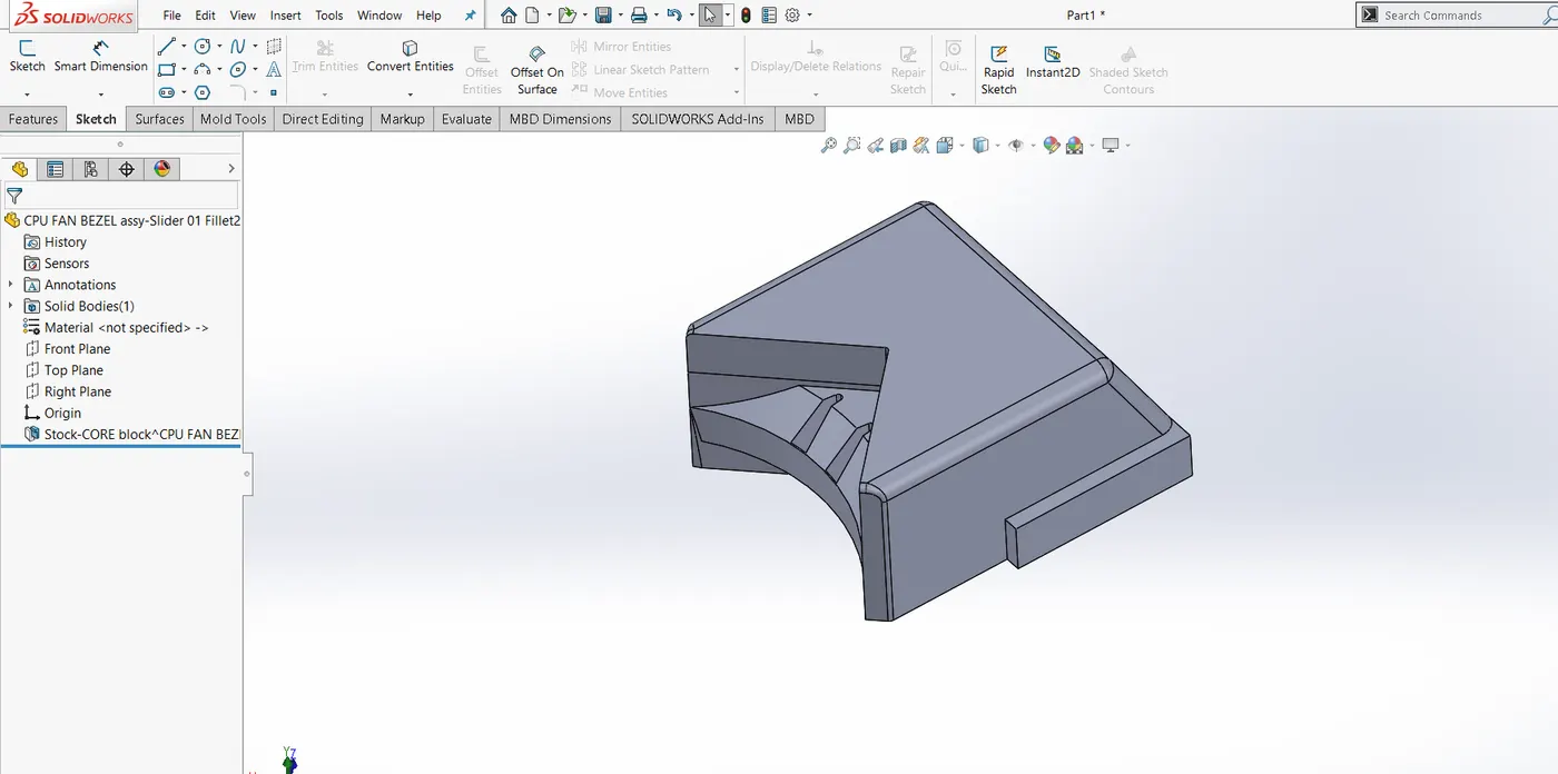
Inserts; Since there is no feature having depth of cut more then 25 mm no inserts are present in the feature.
Creating Sprue , Runner & gating system: Considering the sprue directly at the centre of component, having 3.5 degress of draft in the outwart direction, inlet dia of sprue to be 5.8 mm.
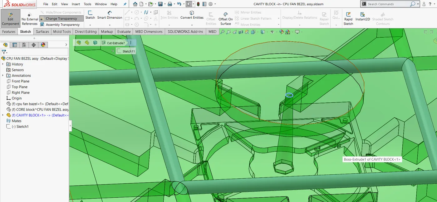
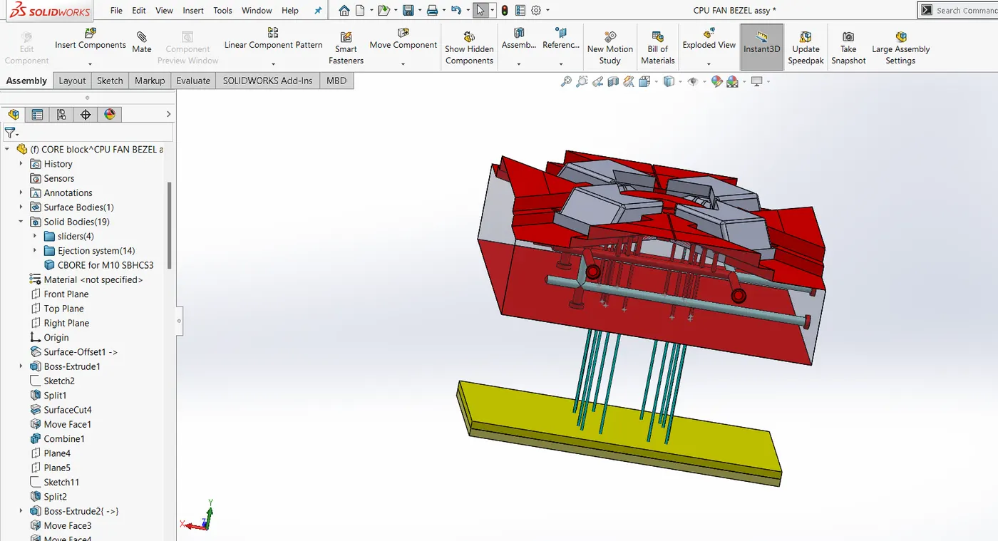
Ejectore plates & pins:
Ejector plate having 10 mm of thk is used with supporting ejector plate. ejector pins having 3mm of diameter with D shape is being used.
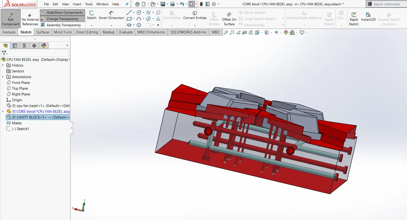
Cooling channels;
For appropriate cooling of the mold, cooling channels are provided in both core & cavity blocks.
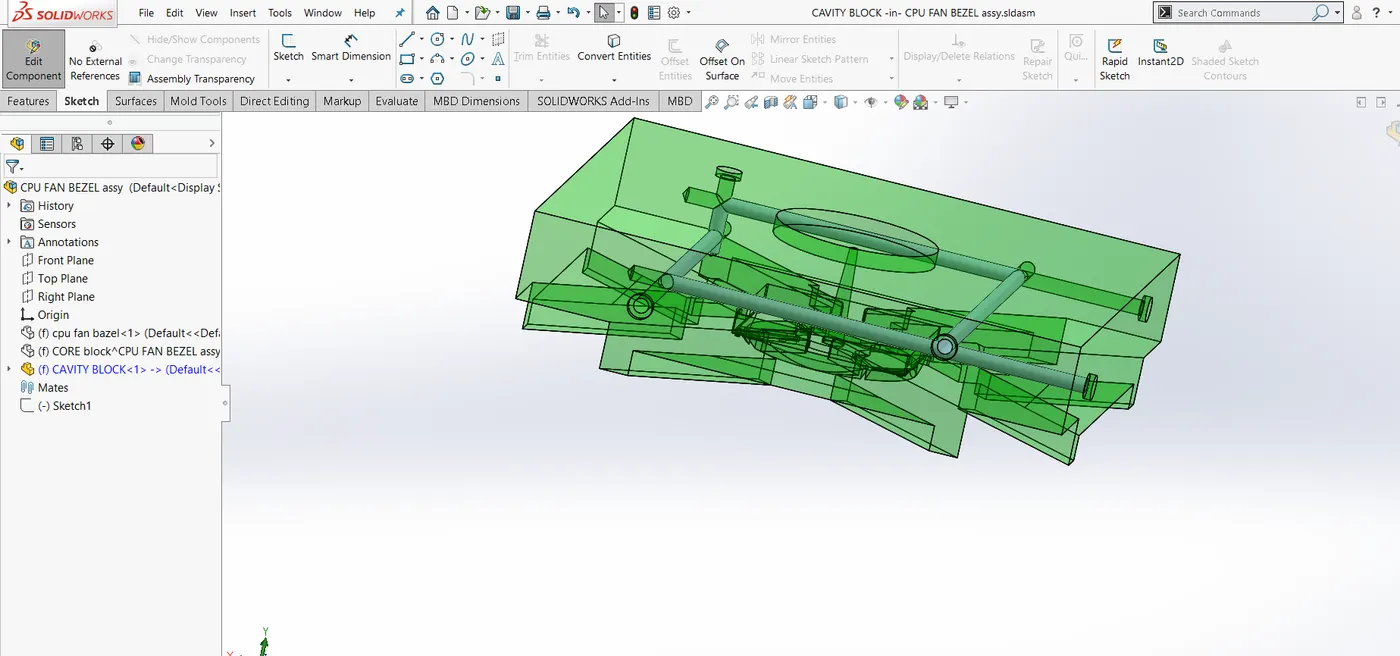
Note: BOdies such as sliders , Ejector pins & plate & main core body are beind created & saved under core body itself.
Link: https://drive.google.com/drive/folders/1-gq8VdoAC1S3EptvaffWCLjXFNT0pDcN?usp=sharing