Week 7 Challenge
Step 1: Draft analysis of given model
Drafting is necessary, for part that can easily be extracted from core & cavity boxed. Drafting is decided with creation of tooling axis. In solidworks tooling axis is considered Perpendicular to the surface selected.
Step 2: Scaling the given model
Every material has its own shrinkage value I.e the material after solidifying shrinks and the actual product has dimension less then the actual product. Theresore scaling is reqiuired to obtained the desirable results.
Step 3: Creation of Parting Line
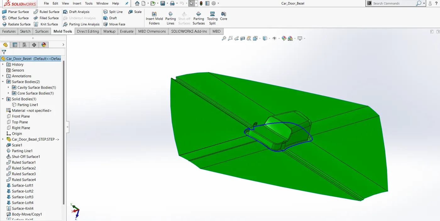
The line where core & cavity box overlaps is called as parting line, & the surface where core & cavity box seperates is called as parting surface.The blue line represent the parting line.
Step 4: Creating Shut off surfaces
The open area in the product are to be closed such that the core & cavity box seperates. It helps in forming two seperate surfaces.
Step 5: Core & Cavity surfaces
After creating shutoff surfaces mold block is seperated into 2 halves, core & cavity. The grees color block is called as cavity block & red is called as core block.
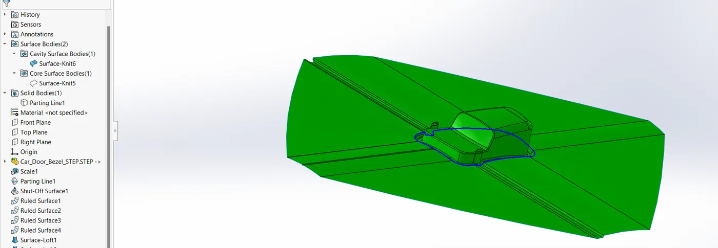
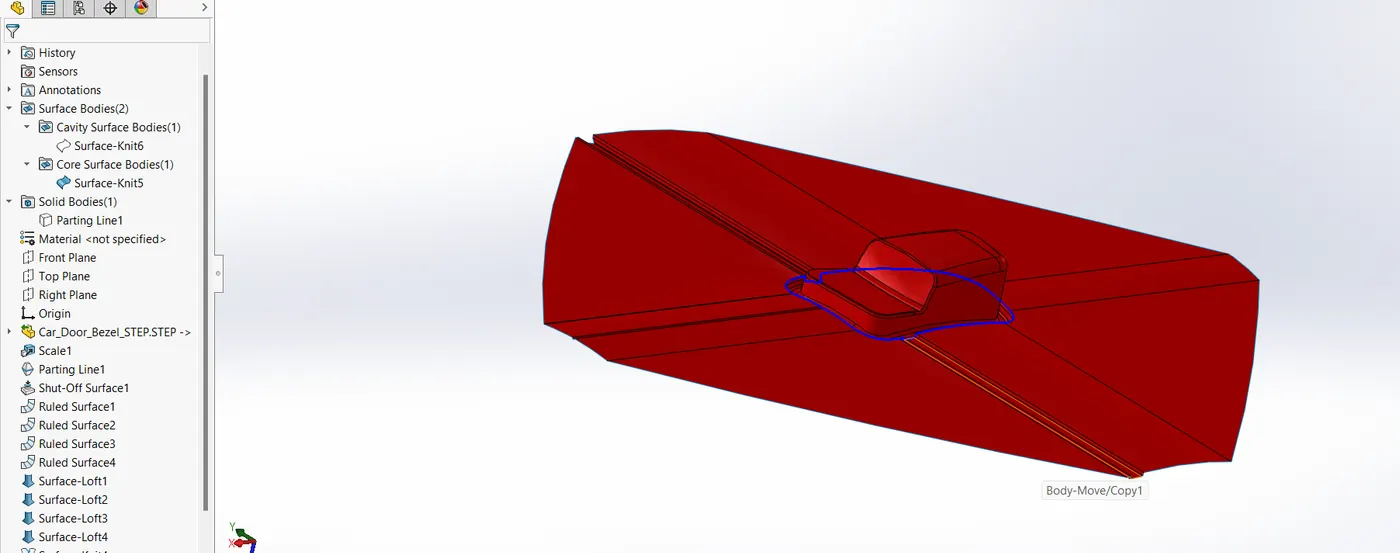
Step 6: Core & Cavity bounting boxes
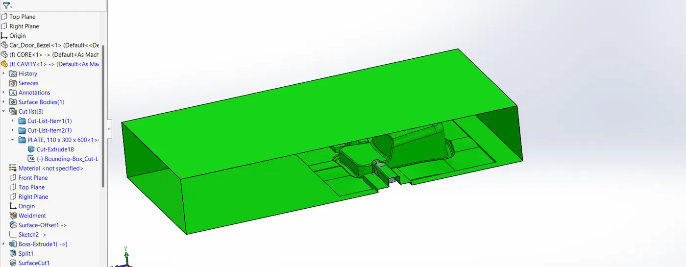
Bounting boxes represent the dimension of block required while manufacturing the core & cavity blocks.
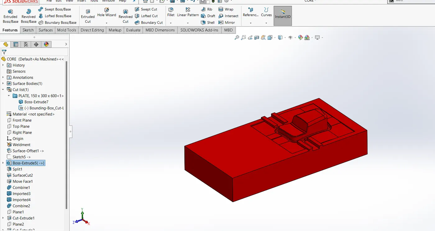
To create bounting box, select weldments, cut list will appear onleft side, right click & select create bounting box.
Step 7: Finding Undercuts & providing sliders
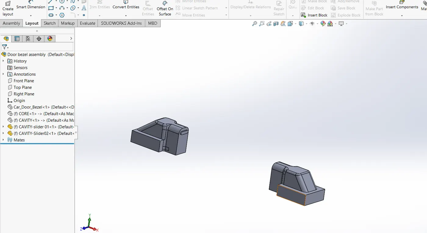
Undercuts present in the product can be eliminated by use of sliders.They have tooling axis different from the main tooling axis & have different mechanism to follow.
link of all files:
https://drive.google.com/drive/folders/1YHjR8zYORcDK9wD23u9Vza5T8jK1Lgma?usp=sharing