Advanced Sheet Metal Design Using NX Cad Challenge_5_Odd Shaped Enclosure
- Title of the Project: Conversion of Solid Body to sheet metal using NX CAD
- Objective: To convert a given odd body to sheet metal & study the tools needed for conversion.
- Introduction : Sheet metal is metal forming process usually formed form metal sheet of thickness 0.6 mm to 10mm respectively.The sheet metal is generally associated with press machines and press working.Press working is chipless manufacturing process by which various components are produced from sheet metal. Press machine consists of frame that supports a ramp and bed and a mechanism for the operation of the ram. The thickness of the sheet is measured in terms of gauges. Higher the gauge no., the lower the thickness.
- Design methodology / approach (To be explained with the help of Flowcharts only):
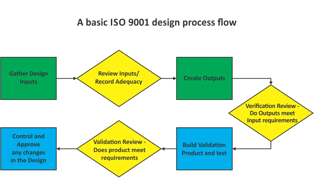
Gather inputs: The design has to start with the problem definition for which the design is to be done and then the design is to be presented to the in-house team as per their specification.
Design Inputs: This is really the first step of the design process, and basically ensures that you make sure you gather all the requirements for your design. The inputs that you have are sufficient enough to satisfy the problem definition or the end user requirements.
Create Outputs: After you have all the data now you can its time to design the basic model based on all the previous that you had gathered.
Verification Review : After the basic model and idea has been made available now it's time for verification of the design. Here a CFT team developed that gives various inputs depending upon the manufacturing end user limits etc
Build validation: A optimized drawing is then created based on the input conditions and the verified with end user requirements.
Validation Review:The design is then validated with inputs from customer/ Problem definition, and finally a clay model is designed for the complete overview of the product.
Documentation: Documention is necessary in every steps as it keeps track of every changes made ,revision details, updation etc.
5. Description (Need to explain tools/ Features used while designing):
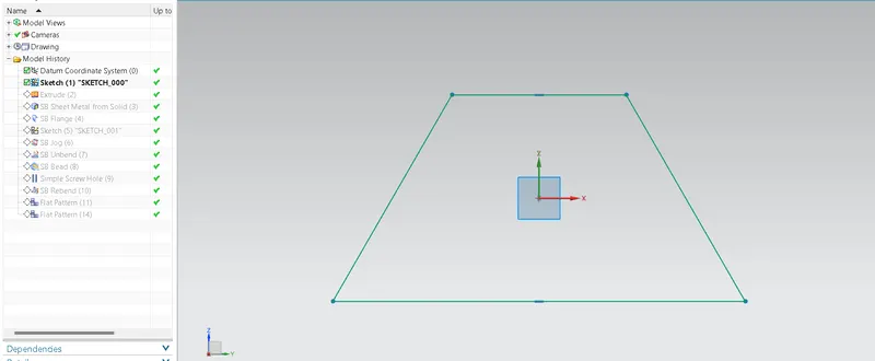
Sketch: It represents the basic design structure of the component namely a 2D sketch.
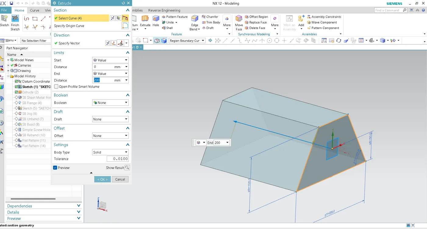
Solid Body: The 2d sketch with help of extrude command is converted to 3D body.
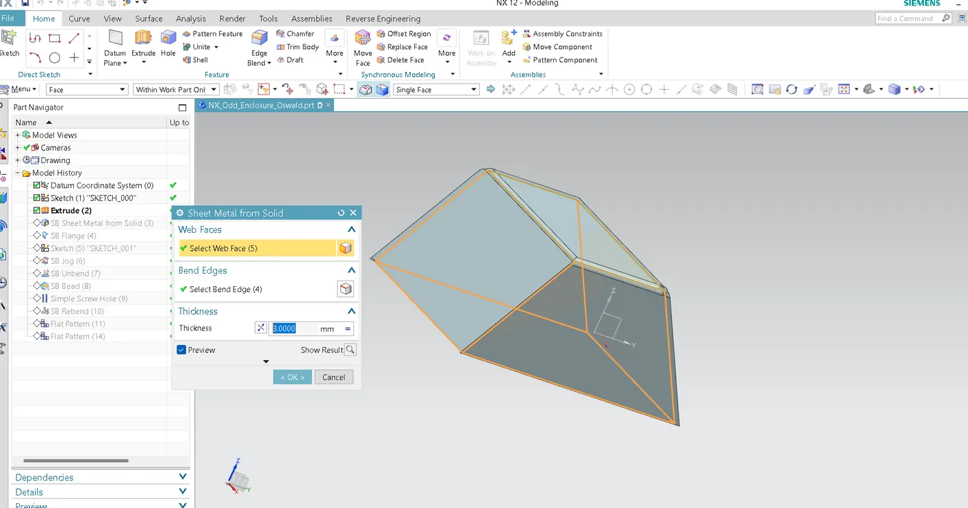
Solid body to sheet metal: To convert the solid body into sheet metal we use the command name solid body to sheet metal. Here by selecting the base portion ,the other 2 sides can be as per the user requirment.
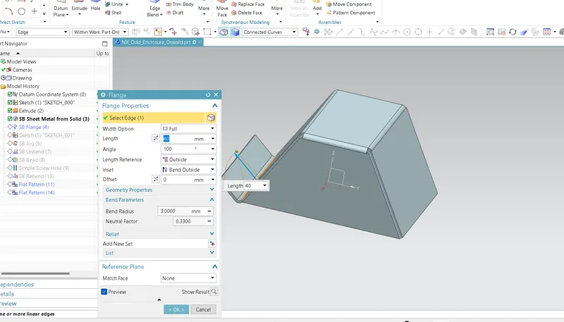
Flanges: Flanges are created as an supporting or an attachment feature on the product.
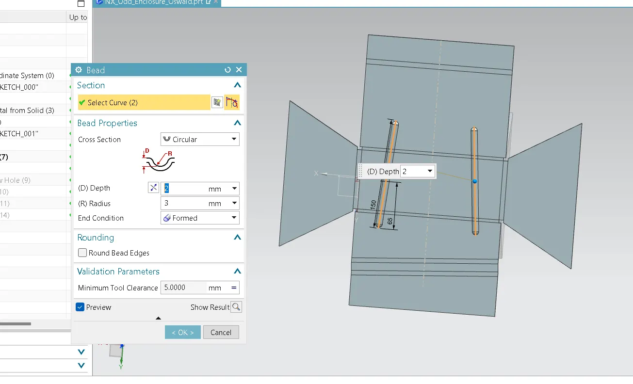
Beads:Beads provides an extra strength to the product.
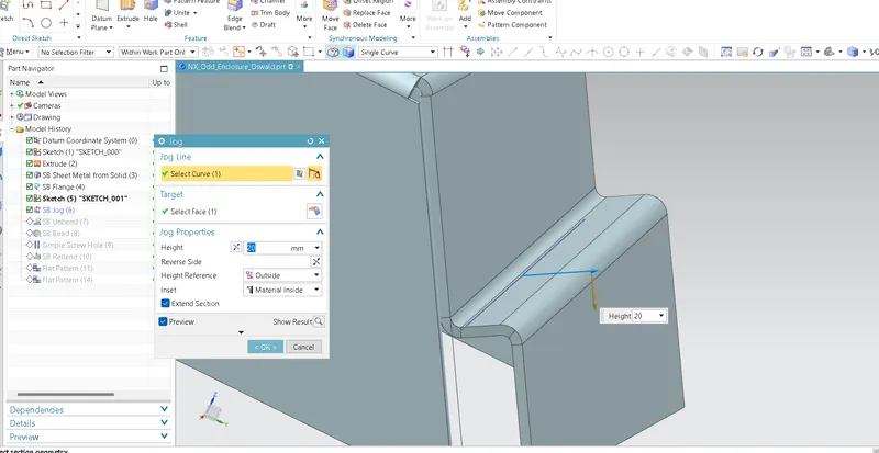
Jogs: It is an offset in sheet metal: It helps us to provide a certain side of the geometry at certain height.
Bends:It is the press working technique by which we can foem a closed structure products.
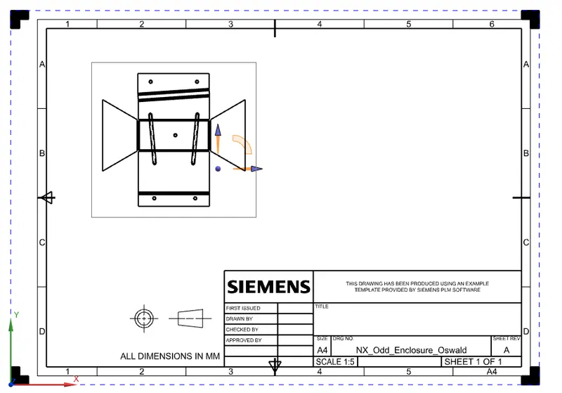
Flat pattern:It gives the 2D pattern of the geometry that we have created i.e we get the blank size of the product.
6. Upload a min of four screenshots of Model in the report. (Front View, Side View, Isometric View and the Top View)
ISO:
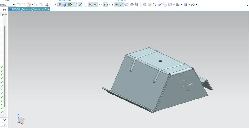
FV:
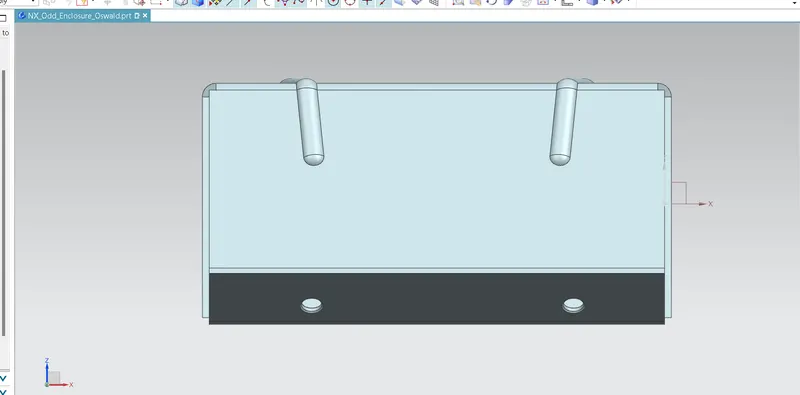
TV:
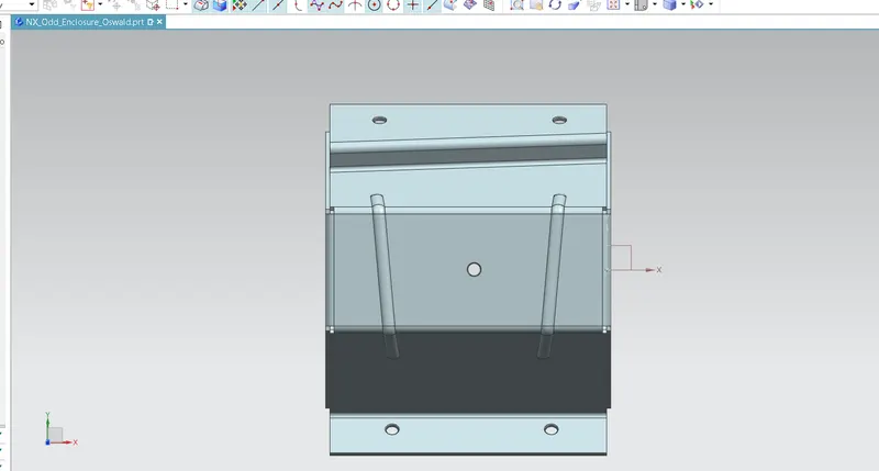
SV:
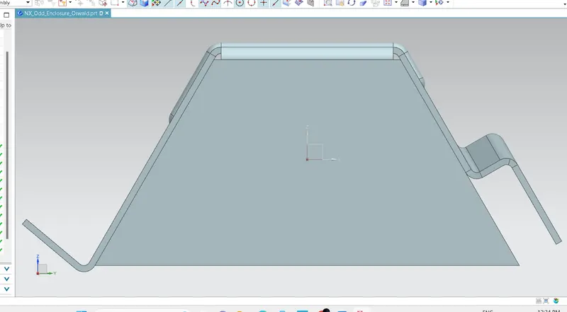
7. Attach Detailed Drawing Sheet Image (If Required):
9.Conclusion:
Successfully studied the conversion of solid body to sheet metal using advance sheet metal operatins in NX CAD