Week 2:- BiW Fixture Basics Challenge
- What is the process of project execution activity?
-- flow chart:
RFQ--> 1st spec discussion meeting -->offer submission--> LOI/PO receipt--> schedule preparation--> BOM preparation-->design concept preparation-->Customer approval--> detailing & drawing release --> Manufacturing /BOP ordering-->mechanical/electrical Assy--> quality inspection-->Internal trial & tooling --> Online trial--> packaging--> dispatch --> Installation as per layout-->Trails & training at customer-->BUf of meeting -->Final handover.
RFQ
RFQ stands for request for quotation.It is 1st & foremost step involved in project execution.In this customer quotes all his requirements,specs, technical offer,timeline etc & other detailing in form of documents.
1St spec discussion meeting :
After Receiving the RFQ the discussion meeting will be carried out on the technical offer, commercial offer, project execution ,Timeline require to complete the project, etc.
Offer Submission:
After the detailed spec meeting offer is submitted to the client for review & feedback.
LOI /PO receipt:
The offer letter received from customer will be reviewed & approved,& finally PO order of the project will be sent.
Schedule preparation:
After receiving the PO offer, the project schedule preparation is done to meet the specific deadline. An estimated amount of time is calculated taking into account the 1st three steps & if required deviations are processed accordingly.
BOM Preparation:
BOM is prepared to depend upon the drawings & each material is listed out.
Design Concept Preparation:
Based on customer requirements drawings are made and sent further for approval from the client.
Customer Approval:
After sharing the drawing with the client, the client confirms if the design meets all his requirements if not necessary deviations /changes are made in the drawing for approval.
Detailing & Drawing release:
After Approval, detailed drawings are released along with dimensions to the customer with detailed specifications.
Manufacturing /BOP ordering:
In this step, manufacturing begins. Before that the required parts such as motors , gears etc are manufactured as per design specification.
Mechanical /electrical assembly:
In this step all the parts received from BOP ordering will be analysed for quality check & then mechanical & electrical assembly of parts are done.
Quality inspection:
After the part is assembled it is further send for quality inspection.In this all the dimensions, position, and coordinates are measured using CMM machine. If the part qualifies it is send to next step else it is reworked again to gain dimension stability.
Internal trial & Testing:
Here working of the assembled components is considered before dispatching it to the customer.
Online Trial.
This is done in front of customer in fully automated sequence.
Packaging:
Packaging is done to avoid transit damage to the product. The damage may cause distortion in product that is to be delivered.
Dispatch:
Once the packaging is done ,the product is then dispatch to the customer.
Installation as per layout:
The installation of fixture should be as per layout, considering functionality, process, and sequence of operation.
Trials & Training at the customer end:
Trials & training is done at the customer end only after proper installation of the fixture.In the technical offer we have provided the benchmarks & the capability of fixture etc. Trials are done to check & show the results to customer.After Trials training is given to staff , engineer,operator,for the process sequence of how the fixture works,loading , unloading etc.
BUY OF meeting:
In this we allow the customer to ask his doubts, and provide additional information related to the project.By the end of the meeting, all the doubts will be cleared satisfying the customer & proceed further.
Final Handover:
Finally after clearing everything the project is finally handeovered to the customer for further use.
2.What are the types of joining processes?
The durability & performance of any structure is largely dependent on the quality &the design of the component's joints.The whole structure can never be made in a single piece.Therefore there are 2 fundamental options for joining material & components
-Mechanical Joining
-Metallurgical joining.
-Mechanical joining:
It is a method of joining 2 or more workpieces in terms of mechanical such as screws , nuts & bolts, rivets etc.In ductile materials the facture can come from fatigue while in brittle the facture is caused as a result of mechanical overloading.
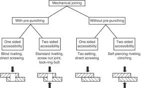
The above figure shows the classification in mechanical joining.
-Metallurgical joining:
Joining of 2 metals with help of metallurgical changes.The metal can be joined by adding filler material or by fusing both the parts together.
Metallurgical joining is further classified as welding, Brazing , Soldering, adhesive bonding, and Diffusive bonding.
Welding:
Welding is the process of joining the material with the help of fusion or melting.A common method of welding known as arc welding consist of generating an electric arc between the electrode &workpiece that helps in the melting of metal &workpiece are joined together. The arc provides enough heat to melt the electrode & the surroundings to perform the welding operation. The electrode passes along the area to be welded. The electrode consists of some flux material, The purpose of this flux is to stabilize the arc formed by generating gases that shield the arc from the surrounding atmosphere.
Some common examples of weldings are TIG, MIG ,Arc welding .
Brazing:
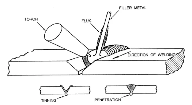
IN Brazing 2 W/P are joined together with the help of filler material that is sandwiched between them.In brazing only filler material is melted to join the 2 components without any heat distortion or fusion in parent material.Material used for Brazing are those having melting temp. of more then 450deg c.Flux is also used during brazing to avoid oxidation from the surface.
Soldering:
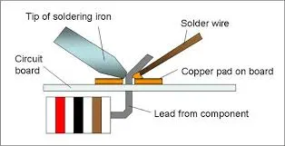
Soldering is done at very much low temp then brazing.IN brazing 2 workpieces are joined together such that only the filler material undergoes melting.Soldering materials are those that melt above 450 deg C, while for brazing th material or filler material is melted with less then 450deg c.
Adhesive bonding:
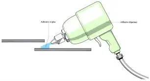
It used bonding materials or chemicals called as adhesives. It is used to join polymers & polymer matrix composites, polymers to metal, metal to metals, and ceramics to metals. Adhesive polymers can withstand shear, tensile & compressive strength. Rought surfaces improve adhesive bonding strength due to mechanical locking.
Diffusion Bonding:
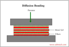
Diffusion bonding is solid stage joining process that undergoes microscopic deformation in the workpiece. It is performed at temp. higher then half the melting point of base metal.Diffusion bonding involves 2 stages,
1. Deformation process of surfaces to be joined.
2.Formation of bonds by diffusion control mechanisms such as grain boundary diffusion & power law creep.
It is very slow process and is performed in an inert atmosphere to avoid oxidation.
3.What is Resistance Welding & its application in the automotive sector?
-Resistance welding falls under the application of metallurgical join.
It is used for joining sheet metal components.The weld is made by conducting a strong current through the metal combination to heat up and finally melts the metal localized points pre determined by the design of electrodes & or the workpiece to be welded.
A force is always applied before, during & after the application of current to confine the contact area at the weld interferance & in some application to forge the w/p.
Types of resistance welding:
*Resistance spot welding
*Resistance seam welding
*Resistance projection welding.
*Resistance spot welding:
The process is used for joining sheet materials/metals& uses shaped copper chromium or zinc chromium alloy electrodes to apply pressure & convey the electrical current through workpieces.
Heat developed mainly at the interference between the 2 sheets eventually causing the material to be welded to melt ,forming the molten pool, the weld nugget.
The molten pool is contained by the pressure applied by the electrode tip & the surrounding solid metal.
Advantages:
-Short weld time, hence high weld speed.
-Adaptable to automation & robotic techniques.
-TYpical BIW contains 5k welds
-Strength & durability of automobile largely depends on the quality of resistance spot welding.
*Resistance projection welding:
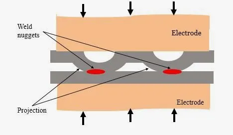
-Projection welding is a resistance welding process for joining metal components or sheets with embosses by directly applying opposing forces with electrodes specially designed to fit the shapes of the workpieces.
-The current & heat generation are localize by the shape of the workpieces either with natural shape or with specially designed projection.Large deformation or collapse will occur in the projection part of the workpiece.
Application: eg weld nut.
*Resistance seam welding:
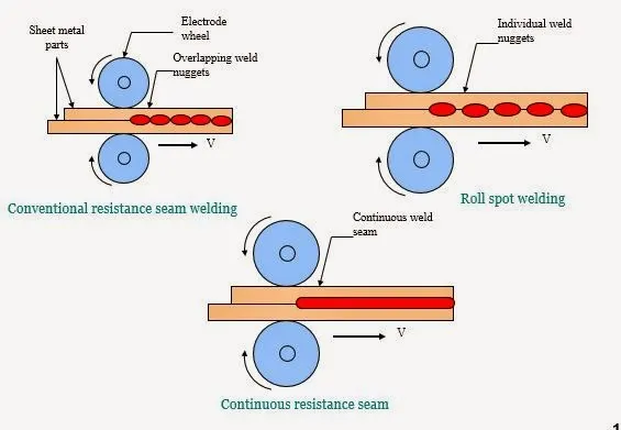
--Seam welding is a resistance welding process for joining metal sheets in continuous, often leak-tight, seam joins by directly applying opposing forces with electrodes consisting of rotating wheels.
-The current & heat generations are localized by the peripheral shapes of the electrode wheels.
Applications:manufacturing of containers ,radiators,heat exchangers etc.
4.What is fusion welding & types of fusion welding with its application in the automotive sector?
--Fusion welding is when 2 parts are welded together having metallurgical changes between them with the application of heat.
-ARC welding
The process involves either consumable or a non-consumable electrode.The ARC is produced at TIP of the electrode & workpiece to be welded by either using AC or DC power supply.
Types of ARC welding:
-Manual metal arc welding
-Gas-shielded metal arc welding
-Gas shielded Tungsten arc welding
-Submerged Arc welding
-Plasma Arc welding.
-Manual Metal ARC welding:
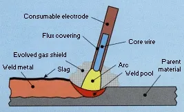
Manual metal ARC welding (MMA or MMAW) also known as shielded metal ARC welding SMAW or formally called as stick welding.
Stick welding is the process where ARC is struct between the metal ROd (electrode flux coated)& the workpiece, both the Rod & workpiece surface melt to create the weld.
-Gas Shielded Metal Arc welding:
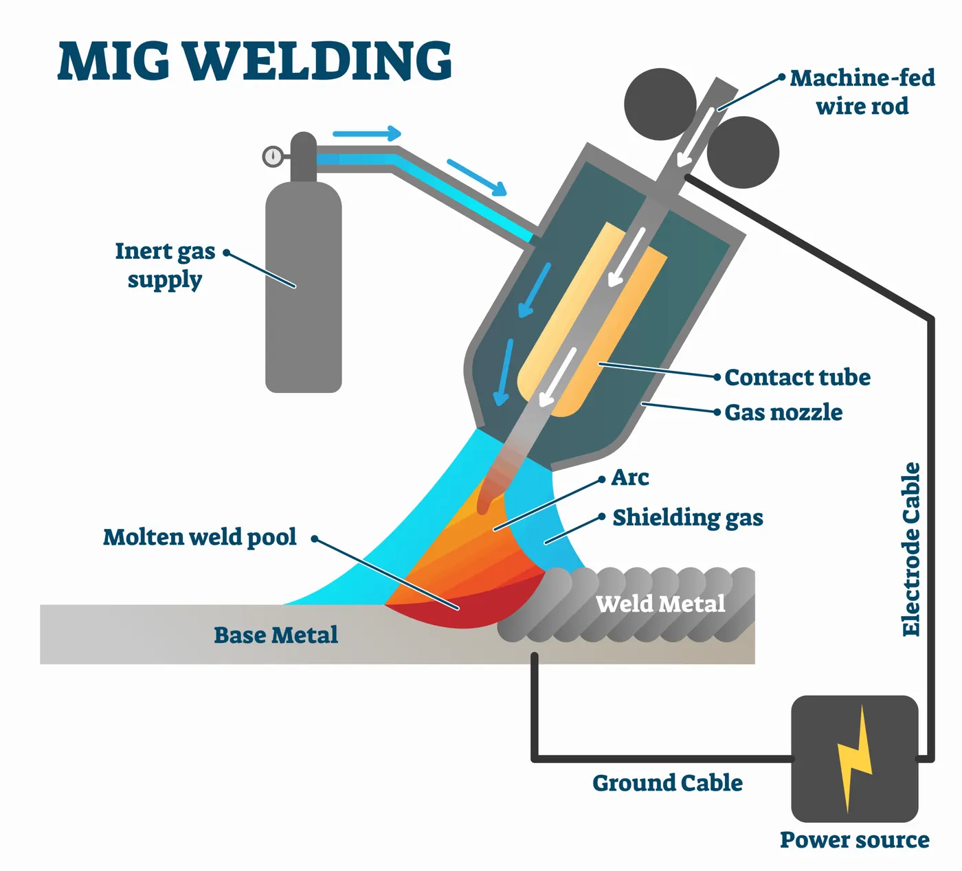
It is often referred as MIG. In this technique, a consumable electrode is used to weld 2 or more workpieces together.
The main components used in MIG welding are
*consumable electrode
*Inert gas supply
*welding head
*Ac/DC power source.
-Tungsten Inert Gas welding:
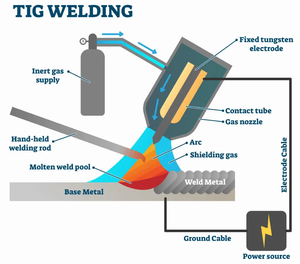
-It is often referred to GTAW process.In this type of welding a non-consumable tungsten electrode is used to weld 2 or more workpieces.It is very much similar to metal inert gas welding.Following components are necessary to perform tungsten inert gas welding,
*Non consumable electrode
*Inert Gas supply
*Filler rod
*Welding head
4.What is the 3-2-1 principle?
--> 3-2-1 principle is used to locate the workpiece constraining 12 dof .
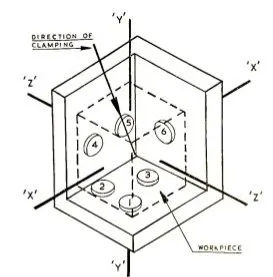
*Minimum 3 locators are used in 1st plane i.e minimum 3 Locator blocks are needed to establish the 1st plane which supports under the w/p.This 3 locators are usually positioned on primary surface & this locators restricts 6 dof: 2 translation & 4 rotational.
The 3 pins at bottom restricts the rotation in +- Z & +-X axis & translation along +- Y
*Round Locating pin in round hole that restricts location in 4 direction is called 4 way locator perpendicular to the previously defined primary plane. Restricts translation in 4 directions.
The 2 pins perpendicular to reference planes restricts translation along +-Z & +-X
*Rounding Pin in slot ,defines in 2 directions restricts the movement in 2 rotational directions.Thus constraining all the degress of the W/P.
The Single Pin restricts the rotation along +- Y axis.
5.Define Body coordinate system?
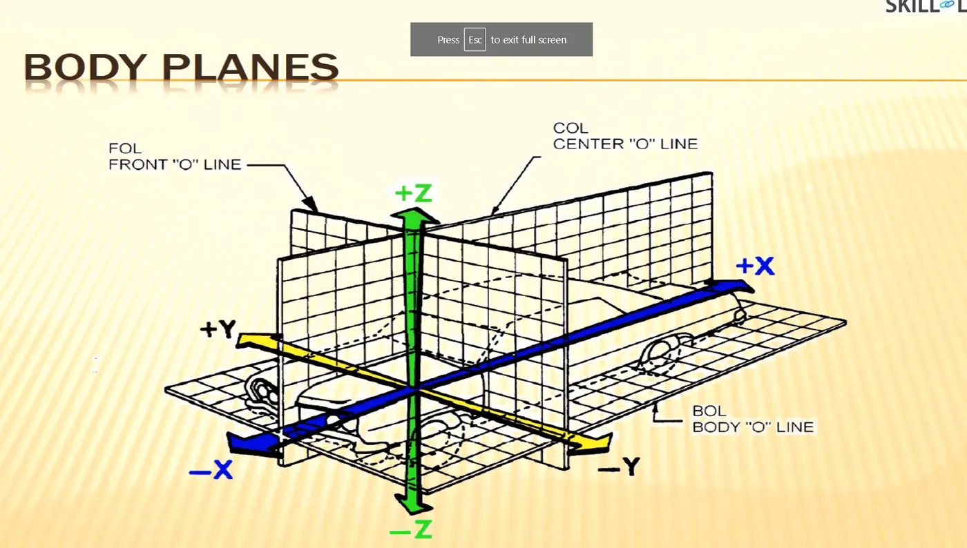
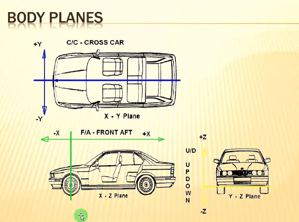
-A coordinate system is a reference system connsisting of set of points ,lines, & surfaces used to define the position of points in space in either 2D or 3D. In general Body coordinate system (BCS) is also called as car line or body line.
-Body planes are reference planes in automotive car.This planes are used to define GD&T of all car parts in an automotive domain.
-Body planes are 3 mutually perpendicular imaginary planes.These are generally considered to be present at the driver position or sometimes at the engine location or at the front end of the car,depending upon the customer.
-The measurements from the planes to the parts are called as body line dimensions.
-This body line planes are called
*FOL
*COL
*BOL
*The measurement along FOL ( Front O Line) or X axis is called F/A Aft
*The measurement along COL(Centre O Line) or Y axis is called C/C cross car
*The measurement along BOL (Body O Line) or Z axis is called U/DUP down.
6.Elaborate Body plane system & its essentials
-Body planes consists of 3 mutually perpendicular imaginary planes which are reference plane for automotive body & also provide basic GD&T for all part of an automobile.
*The body lines are essential for the reasons stated below:
-It defines the exact position of each product in the vehicle with respect to the fixed origin.
-Ensures flawless design for assembly
-While designing lines, all the designs are carried out relative to bodyline viz fixtures, turn tables, etc..
-It assists in the easy location of different parts in the vehicle.
-It helps in creating a standardized system & assists in quality checks.