Project - Analysis of a practical automotive wiring circuit
- Identify each of the major elements in the above automotive wiring diagram.
->
-Battery
-Starter
-breaker
-Junction box
-ignition coil
-distributor box
-Generator
-current voltage regulator
-Foot selector switch
-Ammeter
-Fuse
2. Explain the purpose and working of any three elements briefly.
->
Generator- The generator generates electrical power based on fuel inputs. It is also called as alternator in an electric machine. An electric generator generates electricity from the rotating wheels while braking, transferring that energy back to the traction battery pack. Some vehicles use motor generators that perform both the drive and regeneration functions.
AC generators work on the principle of Faraday’s law of electromagnetic induction, which states that electromotive force – EMF or voltage – is generated in a current-carrying conductor that cuts a uniform magnetic field. This can either be achieved by rotating a conducting coil in a static magnetic field or rotating the magnetic field containing the stationary conductor. The preferred arrangement is to keep the coil stationary because it is easier to draw induced alternating current from a stationary armature coil than from a rotating coil.The generated EMF depends on the number of armature coil turns, magnetic field strength, and the speed of the rotating field.
Working:
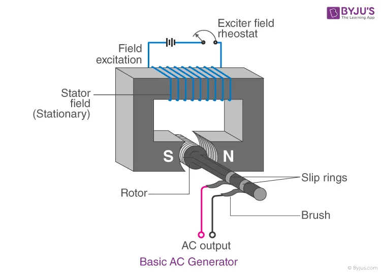
-The AC generator consist of following parts field,Rotor,statorarmature,brush &slip rings:
Field:The field consists of coils of conductors that receive a voltage from the source and produce magnetic flux. The magnetic flux in the field cuts the armature to produce a voltage. This voltage is the output voltage of the AC generator.
Armature: The part of an AC generator in which the voltage is produced is known as an armature. This component primarily consists of coils of wire that are large enough to carry the full-load current of the generator.
Rotor: Rotor is the rotating component of the generator.
Prime Mover :The component used to drive the AC generator is known as a prime mover. The prime mover could either be a diesel engine, a steam turbine, or a motor.
Stator: Stator is the stationary part .The stator core comprises a lamination of steel alloys or magnetic iron to minimise the eddy current losses.
Slip Rings:Slip rings are electrical connections used to transfer power to and fro from the rotor of an AC generator. They are typically designed to conduct the flow of current from a stationary device to a rotating one.
When the armature rotates between the poles of the magnet upon an axis perpendicular to the magnetic field, the flux linkage of the armature changes continuously. As a result, an electric current flows through the galvanometer and the slip rings and brushes. The galvanometer swings between positive and negative values. This indicates that there is an alternating current flowing through the galvanometer. The direction of the induced current can be identified using Fleming’s Right-Hand Rule, where thumb denotes trust or direction of motion, first finger denotes magnetic field,then the 2nd finger denotes the current carrying conductor.
Advantages of alternator:
-They can easily be stepped up or step down
-Loses or comparatively lower the DC
FUSE:
Fuses are the protectors, these are the safety devices which are used to protect the home appliances like televisions, refrigerators, computers with damage by high voltage. The fuse is made up of thin strip or strand of metal, whenever the heavy amount of current or an excessive current flow is there in an electrical circuit, the fuse melts and it opens the circuit and disconnects it from the power supply. Also, it works as a circuit breaker or stabilizer which protects the device from damage.Their strips are made up of aluminum, copper, zinc & it is always connected in series with the circuit to protect from overcurrent in the running cables.
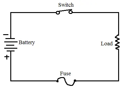
Working: The fuses work on the principle of the heating effect of the current. It’s made up of thin strip or strand of metallic wire with noncombustible material. This is connected between the ends of the terminals. Fuse is always connected in series with the electrical circuit.When the excessive current or heat is generated due to heavy current flows in the circuit, the fuse melts down due to the low melting point of the element and it opens the circuit. The excessive flow may lead to the breakdown of wire and stops the flow of current. The fuse can be replaced or changed with the new one with suitable ratings. The fuse can be made up of the element like zinc, copper, silver &aluminum. They also act as a circuit breaker which is used to break the circuit when the sudden fault occurs in the circuit. This is not only a protector but it is also used as a safety measure to prevent humans from hazards.
Fuse are classified into different types Ac fuse & Dc fuse.
AC fuse are smaller in size. They oscillated 50-60 times in every second from minimum to maximum.
Type of AC fuses:
Low voltage types & high Voltage types.
Low voltage types are : cartridge , rewireable, sticker ,switch dropout type fuses.
High voltage types: Cartridge , liquid, expulsion type HRC fuses.
3- Foot selector Switch
-A Footswitch is a switching device which is operated by the user's foot. They are used throughout a whole host of industries to operate machines or devices giving the user full use of their hands.
Working:
The working principle of this switch is similar to an electric switch. This switch includes two contact points and the wires of this switch are simply connected to the circuit in a device.When Normally Open (NO) contacts within the switch are not getting connected, then the circuit in the device is not connected, so the device will be turned OFF. Once this footswitch is compressed then two contacts will be closed so the electric circuit will be connected and the machine will be turned ON.When Normally Closed (NC) contacts within the switch are closed, then the circuit in the device is connected until the switch is compressed so it breaks the circuit & the machine will be turned OFF.
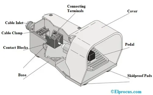
Foot switchconsists of following components,
Pedals: A pedal in this switch is operated through the foot. These are available in different shapes, colors, and sizes based on the type of switch. The pedal in this switch has a spring action to press easily on foot.
skidproof Pads: The skid-proof pads in the switch are arranged at the bottom of the switch to give support to the entire switch from slipping. These pads are designed with non-skid materials like rubber material.
Cover: The foot switch guard covers are mainly used to give protection by avoiding damages occurred by external forces.
Contact Blocks:A contact block is an essential connector simply used to make or break an electrical circuit. These are usually found in switches, circuit breakers, and relays.
Base block:Connecting terminals:Connecting terminals in foot switches are called modular blocks including an insulated frame that protects a minimum of two or above wires together.
Working:
The working of the foot switch is similar to any other electric switch. This footswitch includes contact points and the switch wires are simply connected to the circuit of a device or load.Once the pedal of the switch is not compressed with the foot, then NO (Normally Open) contacts in the switch are not closed; the electric circuit is not connected, so the load or the device is turned off. Similarly, once the footswitch is compressed by the foot, the contacts in the switch will be closed by connecting the electric circuit so the load or the device is turned ON.
3.If the total load is 10A from battery, what should be the fuse rating?
- Fuse rating = (watts/volts) x 1.25
Fuse rating= VI * 1.25/V = I*1.25= 10*1.25= 12.5A
4. If 500W is the load, what is the voltage and capacity of battery you recommend?
- P= 500W
-V=12V
-I =P/V = 500/12 = 41.67 A
-Capacity of battery = Current * Time (in hrs) = 41.67 *1 =41.67AH
5.Identify any two elements which are connected parallel to each other. Why they are connected in parallel?
- Parallel connection are when 2 nodes are in common with each other. Parallel circuit connection makes it possible to connect loads to their individual switch.
eg:
-Generator
-current & voltage regulator
They are connected in parallel so as to maintain proper potential difference.
6. Identify any two elements which are connected in series. Why they are connected in series?
-Starter - is connected in series directly from the battery
-Ammeter is connected to current & voltage regulator
-Fuse
they are connected in series in order to protect the circuit