Fender Design
Fender:
A plastic or metal body /enclousure covering the tires of the car is called as fender. The primary purpose of fender is to avoid the debris falling out of the car into the engine compartment and also it should not hit any of the pedestrials side ways.
Given the following conditions in the diagram we need to design the front fender of the car.
1.The front fender design starts with ofsetting the surface curve from the point of front bumber to 150 mm towards the Drip area .
2.The 2nd section the plane is plotted using point on curve , thereby selecting the 1st plane and projecting it offset to 200mm towards the drip section.
3.To determine the gap between the 2 planes , we select the plane and the single face of drip area there by creating the intersection on the face.
4. Similarly we create every area for each mounting for each of the major area , namely ; Drip area( the area where the front fender is attached to engine compartment); A pillar Mounting ( The area where the front fender gets attached from over the roof of the car); Sill area ( the bottom most area of fender which is attached to plastic or fiber mould);Front bumper mounting ( The area where thr front bumper is mounted to front of front frnder region).
5. Embosses : Embosses are created to strength up the part. Generally embosses are require in the region to distribute the load so that the part does not bend . Therefore emboses are created only in the Apillar mounting region, and drip area region. You can also create emboss in the sill area and bumber region ,but usually not require since it might be difficult to mount.
6. Creating the RIBS /darts: To create the darts it is necessary that the part should be sewed and there shall be no edge bend on the surface . Select the dart option there be selecting the require 2 surfaces 1 by 1 helps in the formation of darts. Darts provide an external strength to the cantilever portion so that the portion stays for the longer time in the position..
Fig 1.1 :-Fender Structure
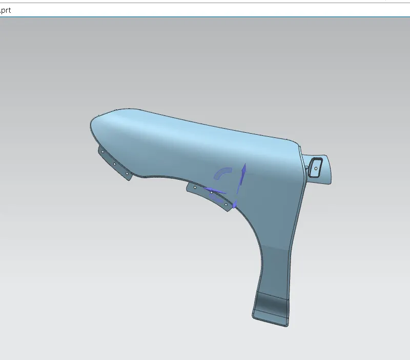
Fig:2.1: emboss on Apillar mounting:
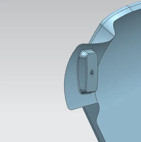
Fig 2.1.1: Rib on Apillar mounting.
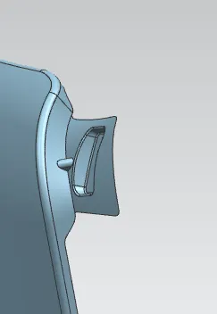
Fig 2.1: Emboss on Drip area
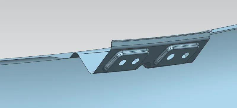
Fig 2.2: Rib on Drip Area:
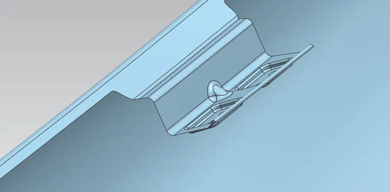
Fig 3.1: Bumper mounting region
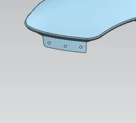
Fig 4.1: Baffle mounting region
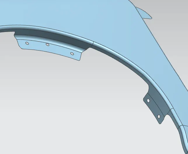
Fig 5.1: bottom or rear fender mounting region.
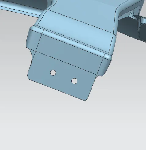
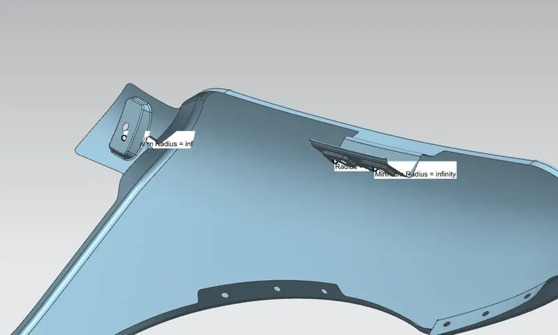
The emboss surfaces must have no radius of curvature , because if there is presence of curfature the part will not rest evenly throughout which results in uneven surfaces . And ergonomicaly this wont look good. Therefore the emboss surface should not have any curvature.
The holes provided on each of the mounting feature is to fasten the fender with the respective mounts.
Note : The holes provided in the mounting region should be perpendicular or along the axis , so as for easymanufacturing.