Week 12 Challenge
Creation Of ejector Pins:
After solidification of component inside core & cavity blocks inorder to eject the part out side ejection pins are used. General diameter of ejection pins varies from 3-6mm. Depending upon the surface ejection pins are divided into 4 main categeroies,
1.Pin ejector system : easy to manufacture and are mainly used in manufacturing industry.They are furthur classified into 3 types. Dia of pins varies from 1.5 to 6 mm.
2.Sleeve ejector pin: This Pins are used where injection molded parts have very deep hole.
3. Stripper plate injection system:This pins are used in parts that are having very thin wall thickness.In this type entire stripper plate along with part is ejected outwards.
4.Blade ejector system: If customer reqquires no gate marks on the plastic components this technique is used.
<< Ejector system:
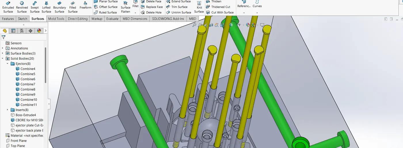
-> In the core body, to create Pins of 6mm diameter circles are drawn & then splitted with the help of split command inbetween the planes. Relief of 0.5mm from walls are provided.
->Other sketch on the same face is sketched & a circles are extruded to create Pins.Since the surface is not flat D type pins are considered.
-Ejector plates:
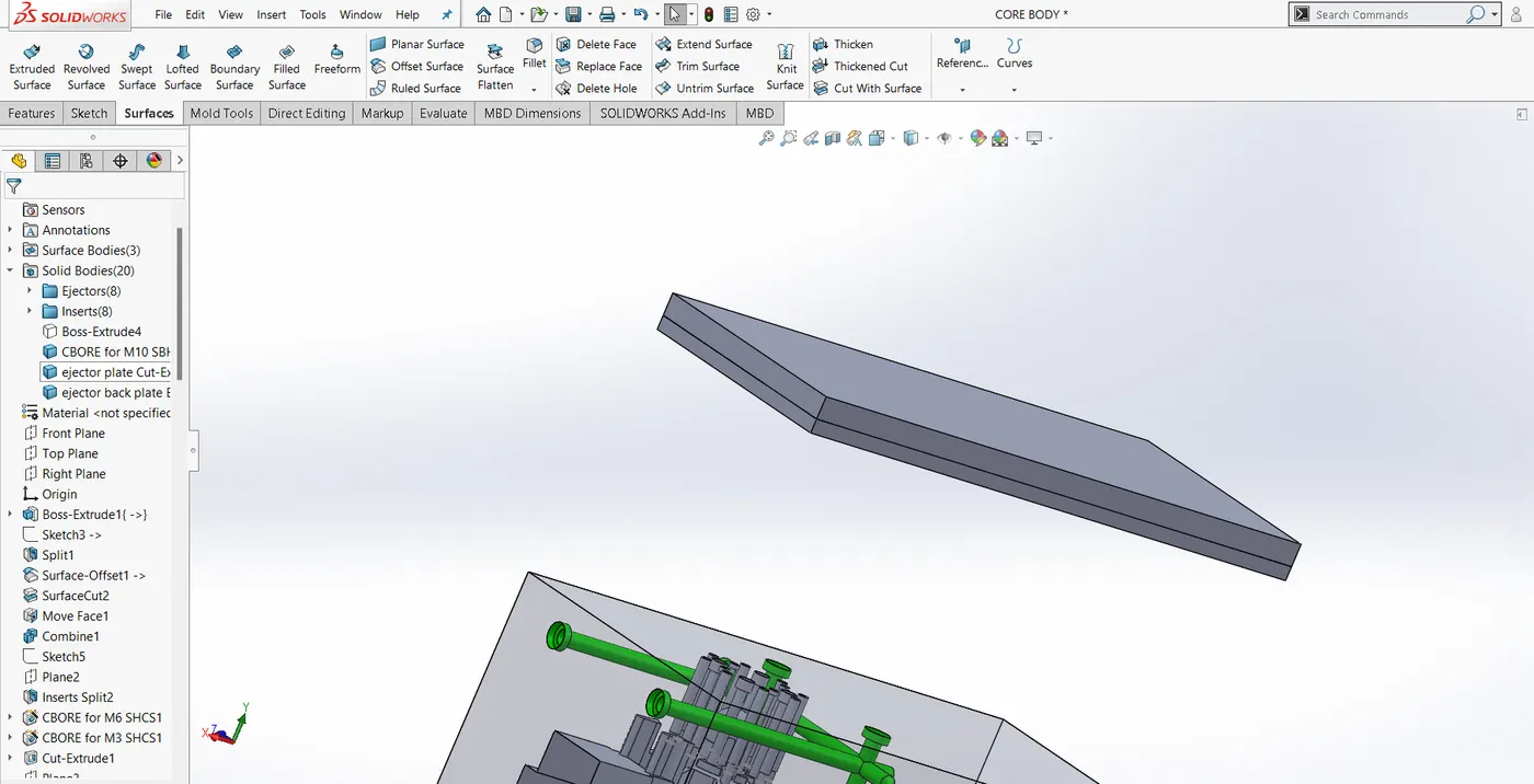
The Ejector plates helps in holding the ejector pins and is supported by ejector back plate with help of bolts.
-Runner & Gate system:
*The molten material enters the core cavity block via spur dia of 5.8 mm & draft of 3.5 degrees.
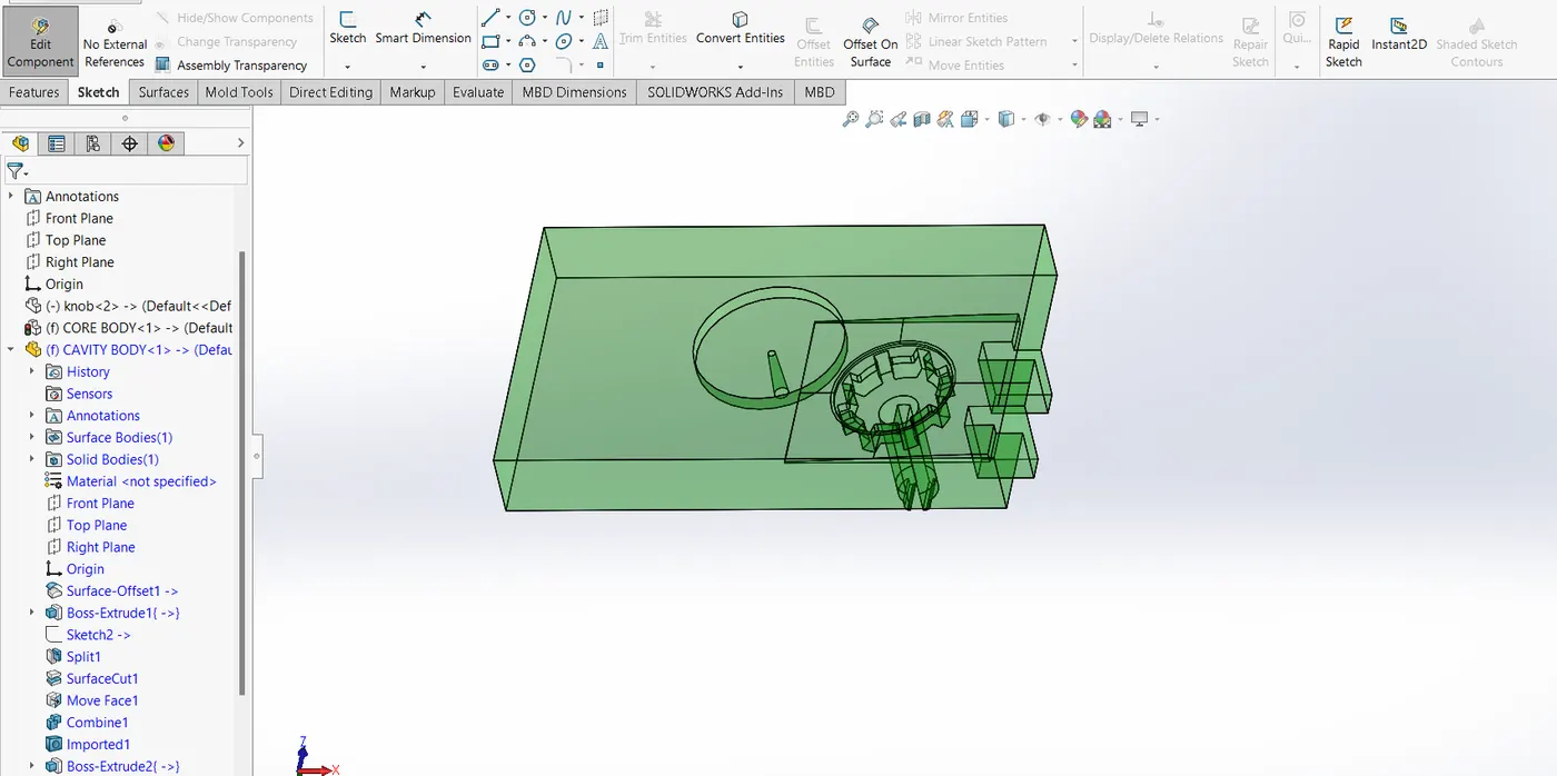
*Cold slag: It has dia similar to that of sprue dia at inlet. After the mold solidifies there an excess of molten material present into th slag. This excess material is removed with help ejector pins.
*Runner: A pathway through with gate and sprue system are connected to each other is called as runner.
* Gate :The molten material enters into mould cavity via gate.
-> Air vents:
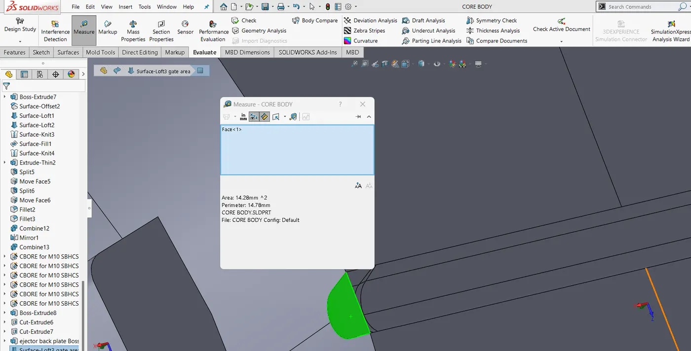
The air trapped inside the mold should be guided properly to avoid voids in part.The air to pass on should not have more depth otherwise the fluid will pass through it resulting in trapping of air.
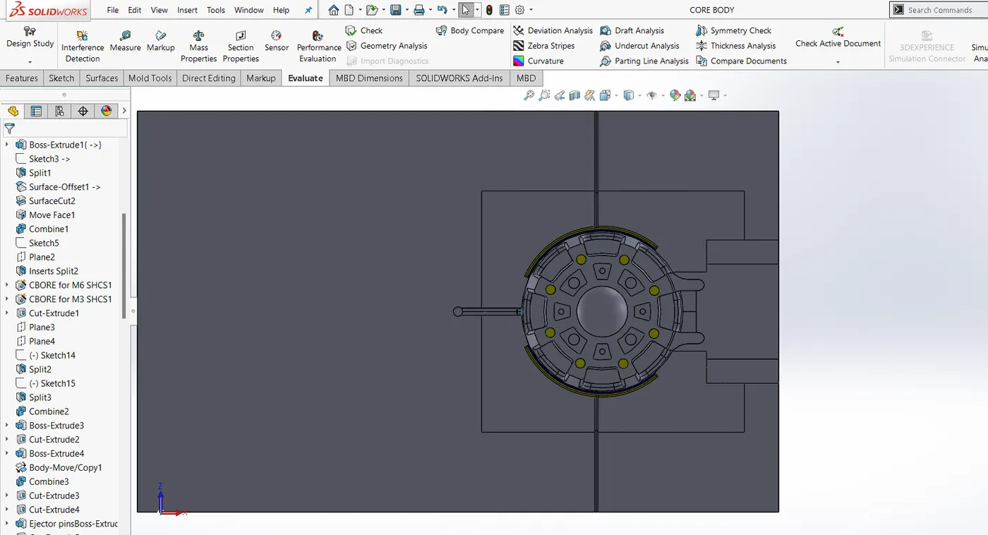
The air way to be present in once in every 200mm distance.
*Cooling Channels:
-->Cooling channels are to be present in such a way that uniform cooling is obtained throughout the part body.Cooling channels are provided along all the direction to obtained optimum results. Tehy are located in core & cavity blocks.
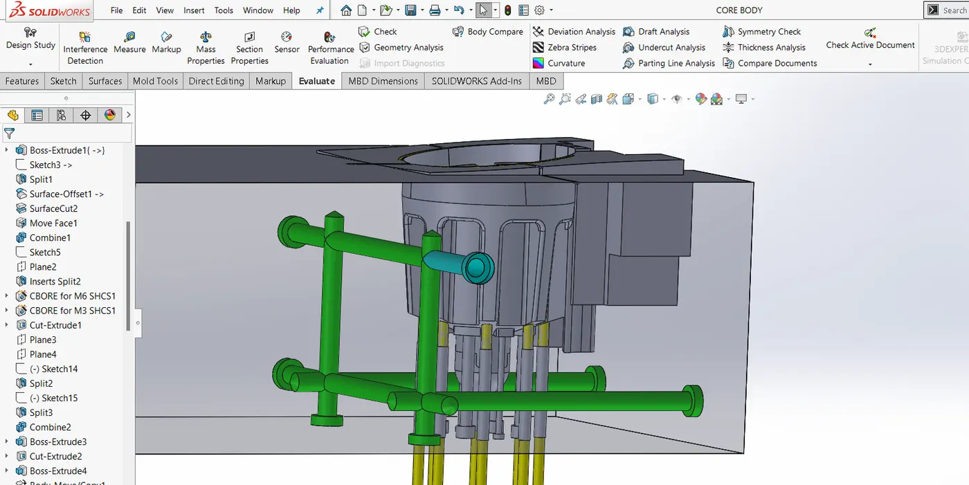
Cooling channels are constructed using hole wizard command & constructed using 2D/3D sketch.
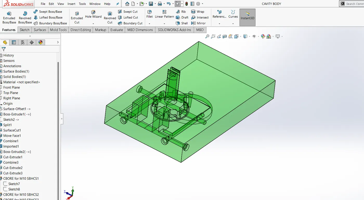
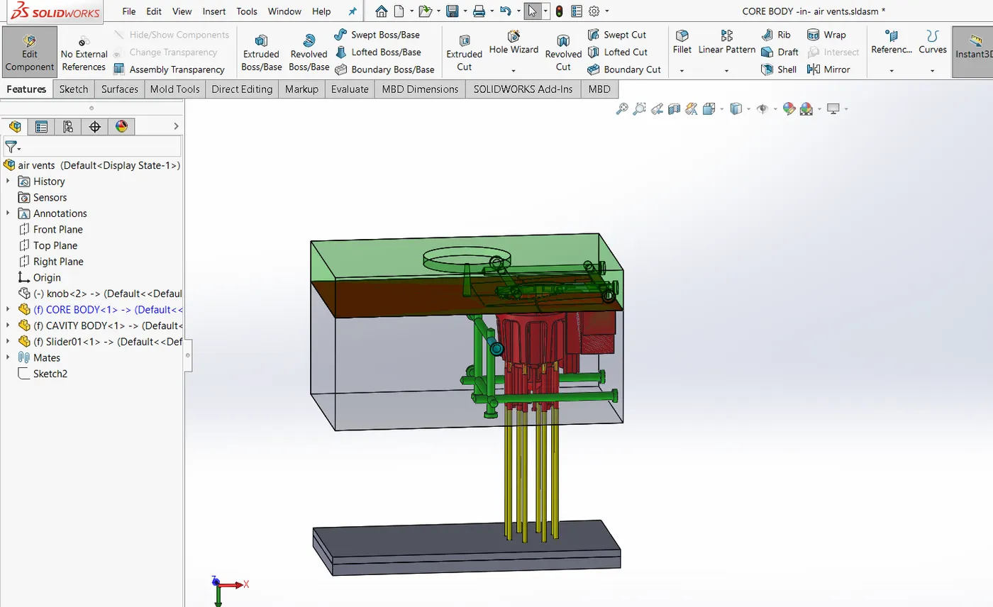
Note: Ejector pins, inserts are considered under core system. The can be latter saved as seperate files.
GD: https://drive.google.com/drive/folders/1K_yD_4I7VrQUthUyzqu02ntmA5ytgoU5?usp=sharing