Week 3 Sheet metal Bending challenge
ANSYS CHALLENGE 3: SHEET METAL BENDING CHALLENGE
AIM:
To evaluate the simulation for sheet metal bending process with three different materials, friction coefficient, and refine the mesh.
OBJECTIVE:
Evaluate the result for the sheet metal bending process in three cases:
Case1: Compare the result for three different materials Aluminium alloy 1199, Copper Alloy NL, Magnesium Alloy NL, and find out equivalent stress, equivalent strain in the Y direction.
Case 2: With material Aluminium alloy change the friction coefficient factor to 0.19 and compare the result with case 1.
Case 3: Refine the mesh on the plate with Aluminium alloy and compare results.
THEORY:
Bending is a metal forming process in which a force is applied to a piece of sheet metal, causing it to bend at an angle and form the desired shape. A bending operation causes deformation along one axis and forms the desired shape. A bending operation causes deformation along on axis but a sequence of several different operations can be performed to create a complex part.
Process: Bending of sheets and plates widely used in forming parts such as corrugations, flanges, etc. Bending is a forming operation in which sheet metal is subjected to bending stress thereby flat straight sheet is made into curved a sheet. It gets plastically deformed without a change in thickness. Different types of bending are done with the use of a die and punch V bending, air bending, coining, u-bending, step bending, roll bending, wipe bending, rotary bending, and edge bending.
In this process, one end of the sheet held like a cantilever using a pressure pad, and the other end is deformed by a punch that moves vertically down, bending the sheet.
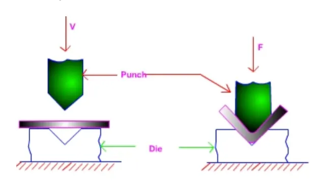
Fig 1: Sheet metal bending process
MATERIALS PROPERTIES:
Aluminium Alloy
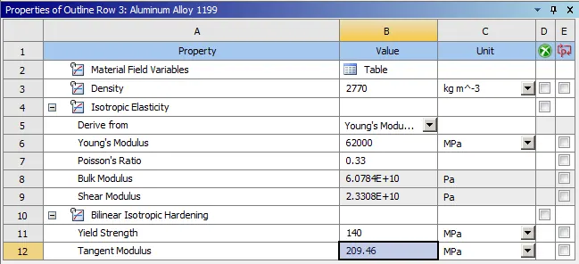
Fig 2: Changing properties value for aluminum alloy 1199
Copper Alloy
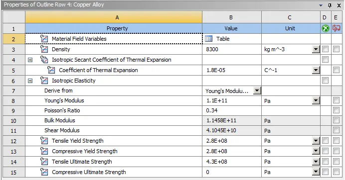
Fig 3: Properties of Copper Alloy
Magnesium Alloy
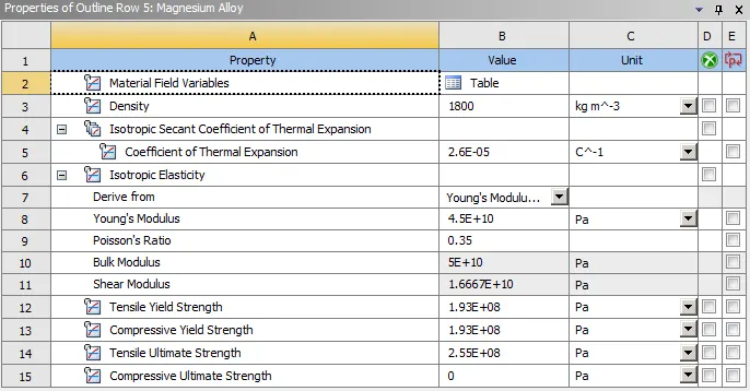
Fig 4: Properties of magnesium alloy
SIMULATION SETUP
Import the geometry in the geometry module and checking any damages or improper surfaces of the sheet any opening the geometry in the
mechanical module.
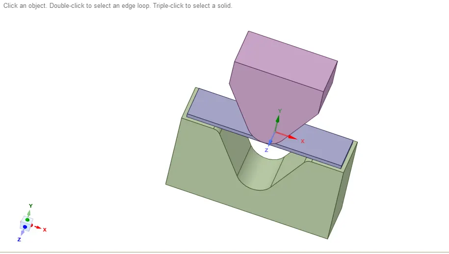
Fig 5: Sheet metal geometry
Geometry
Renaming each part of the geometry as punch, die, and sheet, so it ill easy to call the function of each part.
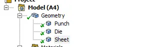
Fig 6: Changing the name of geometry
Connections
For the movement of the punch on the sheet and for the frictional moment the connection is provided to them two contacts are given.
1) Frictional - Punch to sheet
Selecting contact with 3 faces of punch and 1 face of the sheet as target body.
Type: Frictional.
Frictional coefficient: 0.1.
behavior: Auto asymmetric.
Formulation: Augmented Lagrange.
Interface treatment: Add offset, Ramped effects.
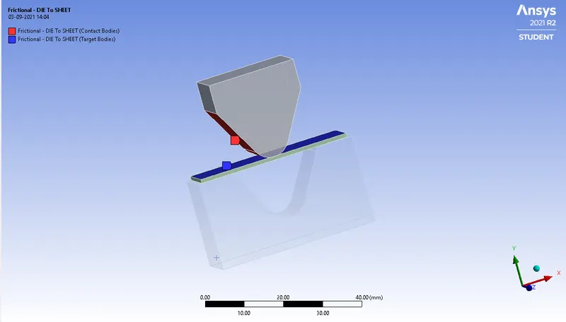
Fig 7: Contacts punch to sheet
2) Frictional: Sheet to die
Selecting contact with 1 face of sheet and 7 faces of the die as target body.
Type: Frictional.
Frictional coefficient: 0.1.
behavior: Auto asymmetric.
Formulation: Augmented Lagrange.
Interface treatment: Add offset, Ramped effects.
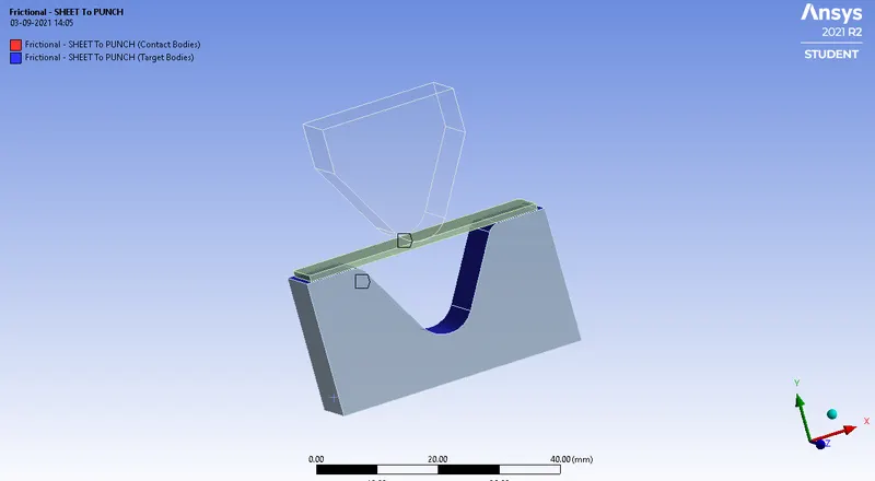
Fig 8: contact sheet to die
Mesh
This geometry has the face to the sheet, die, and punch so the mesh will be varying to each part differently, overall mesh on the geometry is the
default, but for the die and punch the boy selection is done for both with the mesh size 4mm as selecting by body sizing.
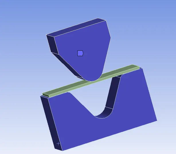 Fig 9: 4mm mesh on punch and die
For body sizing 2 has been selected for a sheet with 1mm size and the body sizing 3 selected for the faces of die and sheet approx 10 faces.
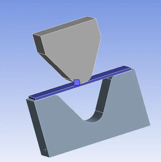
Fig 10: 10 faces 1mm mesh size
And the sheet is a solid part that can be mesh with tetra mesh and it can be done by the selecting insert batch conforming method.
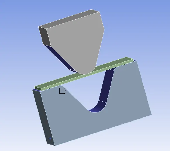
Fig 11: Tetra Mesh method for sheet
As the setting up the mesh on the whole geometry, the mesh has been generated on the geometry.
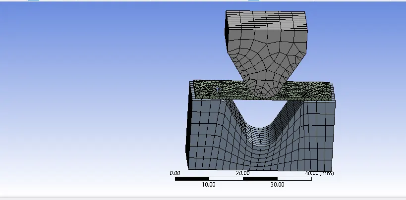
Fig 12: Mesh on sheet metal
Analysis setting
Setting up the analysis settings for the simulation at 10 steps with the end time 10s, with the solver type: direct. The process for this simulation will act like the punch will press the sheet and will love upwards direct after bending it and the die will be at stationer position for the whole process but it will lift up the sheet after the pressing process.
To evaluate the simulation in such settings displacement method to inserted for the simulation.
Displacement for punch selecting the top faces of the punch x,y, and z coordinates to be evaluated in the form of tabular data.
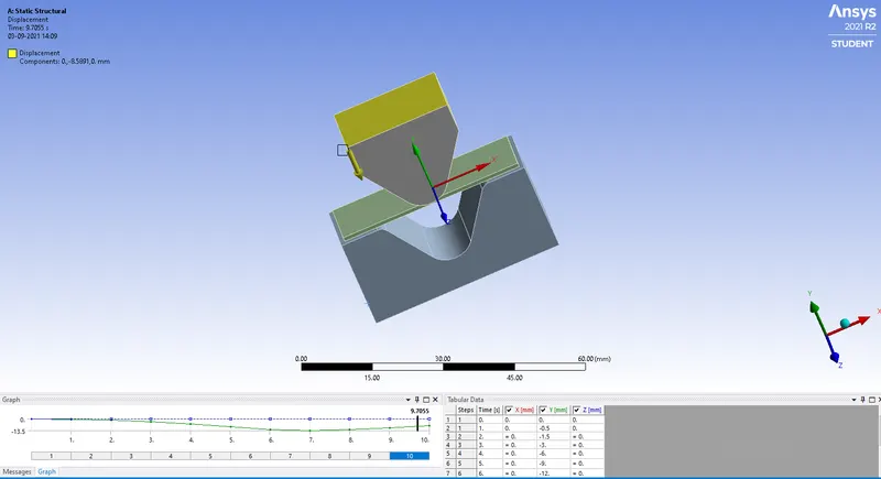
Fig 13: Displacement for punch
Displacement 2 for the sheet which will act as a moment in the z direct by selecting 2 sides' faces and calculating 2z direction in tabular data.
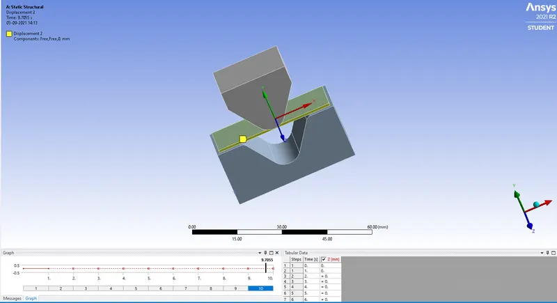
Fig 14: Displacement for sheet
And for the die displacement will act at steps 9 and 10 for minimum displacement to release the sheet at its position after bending and will
calculate the result in tabular form for all three directions.
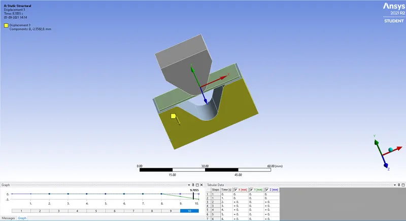
Fig 15: Displacement for die
Solution
After setting up the simulation for the punch, sheet, and die, we need to calculate the solution for:
Mandatory result: Equivalent (Non-mises) stress.
Equivalent elastic strain.
Directional deformation in (-Y) axis.
External Results: Equivalent stress 2 - to calculate the stress on the sheet.
Contact tool- Frictional and pressure on (Punch to a sheet).
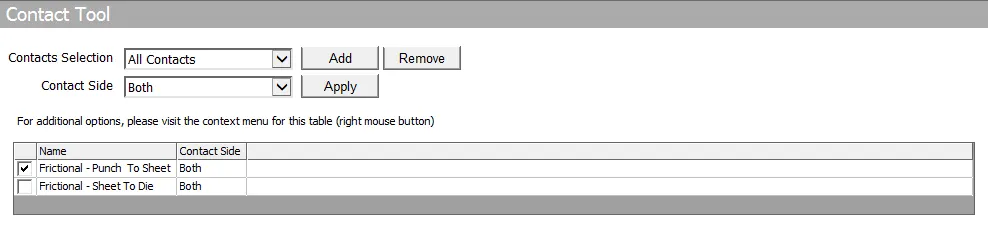
Fig 16: contact tool 1
Contact tool 2 - Frictional and Pressure (Sheet to die).
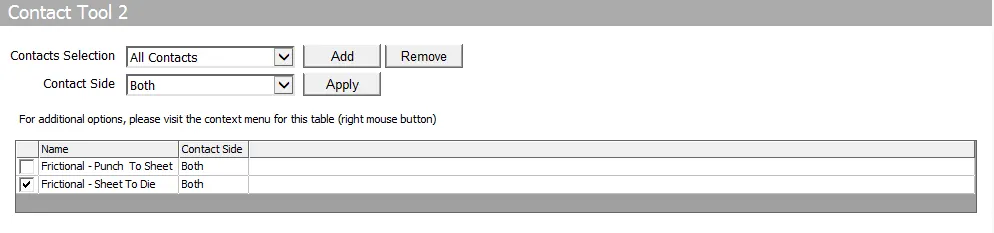
Fig 17: contact tool 2
And force reaction for boundary condition (displacement).
RESULTS
Case 1: For all three materials Aluminium Alloy 1199, Copper alloy NL, and Magnesium alloy NL
Aluminium Alloy 1199:
The equivalent Von -mises stress:
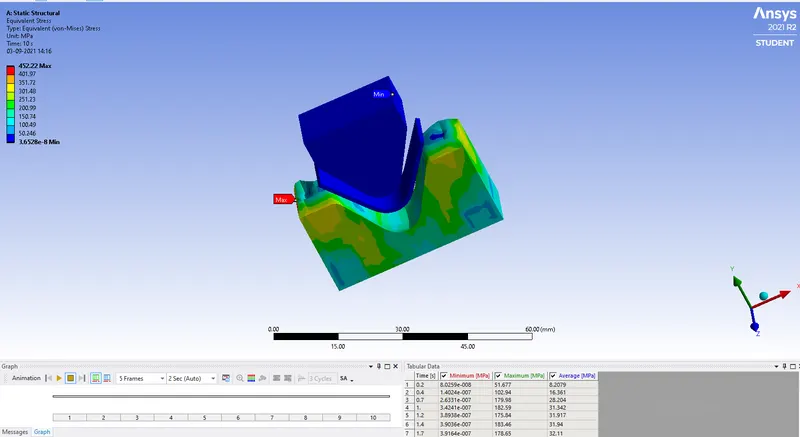
Fig 18: Equivalent Von misses stress
Equivalent elastic strain:
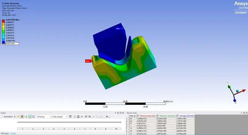
Fig 19: Equivalent Non-elastic strain
Directional deformation:
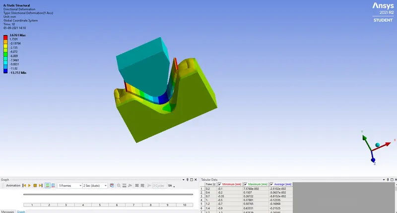
Fig 20: Directional Deformation
Copper Alloy NL:
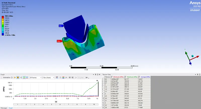
Fig 21: Equivalent Von vises stress
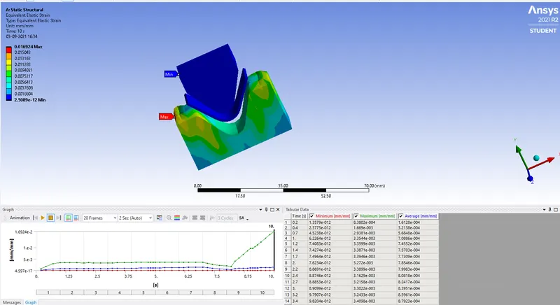
Fig 22: Equivalent elastic strain
Directional deformation
The deformation in the Y-direction.
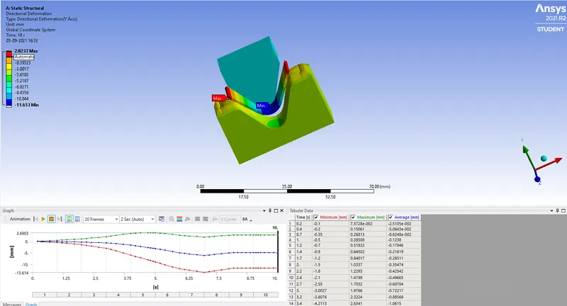
Fig 23: Directional Deformation
Magnesium Alloy AL:
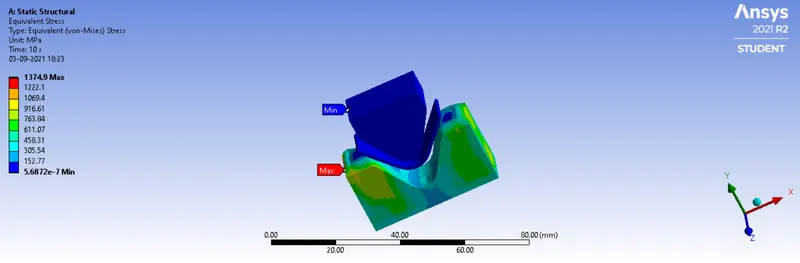
Fig 24: Equivalent Von mises stress
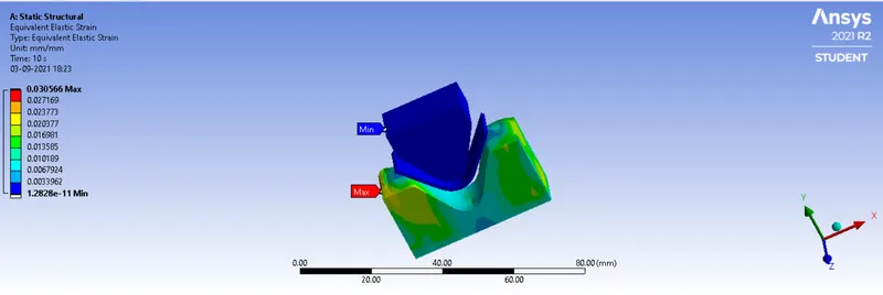
Fig 25: Equivalent elastic strain
Directional Deformation
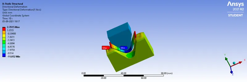
Fig 26: Directional deformation
Case 2: Change in friction coefficient to 0.19 and compare the result with case 1
Friction coefficient (0.19):
Coefficient of friction, the ratio of the frictional force resisting the motion of two surfaces in contact with the normal force pressing the two surfaces
together. Formula: μ = F/N. Thus by changing the case from 0.10 to 0.19 to evaluate and compare the results from case 1
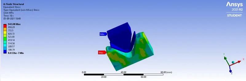
Fig 27: Equivalent von mises stress
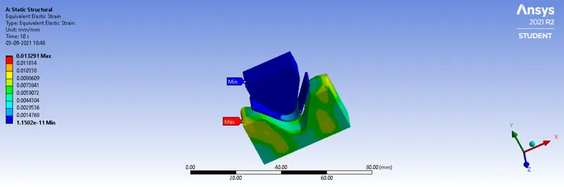
Fig 28: Equivalent elastic strain
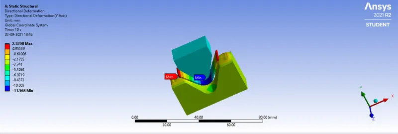
Fig 29: Directional deformation
Case 3: Refine to mesh to the sheet (0.7mm) and compare results with other cases.
Checking how refining the mesh on the plate will change the results from 1mm to 0.7mm and it changes the value for stress, strain, deformation.
Equivalent Von mises stress
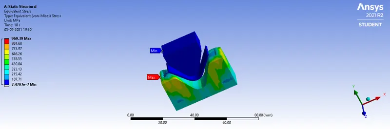
Fig 30: Equivalent Von mises stress
Equivalent elastic strain
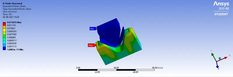
Fig 31: Equivalent elastic strain
Directional deformation
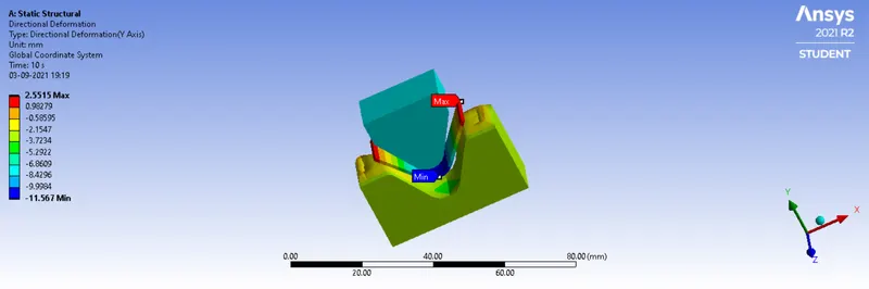
Fig 32: Directional deformation
Results comparison
Case 1:
Comparison of the result for equivalent von mises stress
| Stress Value | Aluminum Alloy AL 1199 (MPa) | Copper Alloy CL (MPa) | Magnesium Alloy AL (MPa) |
| Minimum Equivalent Von Mises Stress | 3.652e-8 | 2.3425e-7 | 5.6872e-7 |
| Maximum Equivalent Von Mises Stress | 452.22 | 1861.4 | 1374.9 |
| Average Equivalent Von Mises Stress | 251.23 | 1004.1 | 763.84 |
The graph and result state that the magnesium alloy has a left effect for equivalent stress compare to copper alloy and aluminum alloy, the
average value for Mg AL is 178.49 MPa, copper alloy is 431.4 MPa, and Aluminium Alloy 1199 is 242.38 MPa.
Comparison of the result for equivalent elastic strain
| Strain Value | Aluminum Alloy AL 1199 (mm/mm) | Copper Alloy CL (mm/mm) | Magnesium Alloy AL (mm/mm) |
| Minimum Equivalent elastic strain | 0 | 2.5089e-12 | 1.2828e-11 |
| Maximum Equivalent elastic strain | 0.0072942 | 0.016924 | 0.030566 |
| Average Equivalent elastic strain | 0.0042523 | 0.0094021 | 0.016981 |
The result visualizes that the magnesium alloy has the highest value of elastic strain compare to copper alloy and aluminum alloy, magnesium
material has the most elastic strain for the sheet as a material.
Comparison of the result for directional deformation
| Stress Value | Aluminum Alloy AL 1199 (mm) | Copper Alloy CL (mm) | Magnesium Alloy AL (mm) |
| Minimum directional deformation | -13.757 | -11.653 | -11.052 |
| Maximum directional deformation | 3.6761 | 2.8237 | 2.7915 |
| Average Directional deformation | -4.072 | -3.6702 | -3.3613 |
There is not much effect on the directional deformation for all three materials, the minimum, maximum, and average values are approximately
similar to a minor change in maximum deformation.
Case 2: Change in friction coefficient of 0.19 and comparison with case 1
| Material | Minimum equivalent von mises stress (MPa) | Maximum equivalent von-mises stress (MPa) | Average equivalent von-mises stress (MPa) | Minimum equivalent elastic strain (mm/mm) | Maximum equivalent elastic strain (mm/mm) | Average equivalent elastic strain (mm/mm) | Minimum directional deformation (mm) | Maximum directional deformation (mm) | Average directional deformation (mm) |
| Aluminum alloy 1199 Friction coefficient (0.19) | 8.0336e-7 | 943.08 | 523.93 | 1.1502e-11 | 0.013291 | 0.0073841 | -11.568 | 2.5208 | -3.741 |
| Aluminum alloy 1199 Friction coefficient (0.10) | 3.6528e-8 | 452.22 | 251.23 | 0 | 0.0072942 | 0.0042523 | 13.757 | 3.6361 | 4.072 |
The results show that for fiction coefficient 0.19 equivalent von misses stress is less compare to friction coefficient 0.10, as the friction coefficient
decreases the result is more likely accurate in comparison to the stress but for the elastic strain and deformation results are approximately similar
their is much effect of the friction coefficient changed value.
Case 3: Refine mesh to the aluminum alloy 1199 sheet and compare results with case 1.
| Material | Minimum equivalent von mises stress (MPa) | Maximum equivalent von-mises stress (MPa) | Average equivalent von-mises stress (MPa) | Minimum equivalent elastic strain (mm/mm) | Maximum equivalent elastic strain (mm/mm) | Average equivalent elastic strain (mm/mm) | Minimum directional deformation (mm) | Maximum directional deformation (mm) | Average directional deformation (mm) |
|
Aluminum alloy 1199 sheet mesh (0.7 mm) |
7.4707e-7 | 969.39 | 538.55 | 1.0883e-11 | 0.013655 | 0.0075862 | -11.567 | 2.5515 | -3.7234 |
| Aluminum alloy 1199 Sheet Mesh (1mm) | 3.6528e-8 | 452.22 | 251.23 | 0 | 0.0072942 | 0.0042523 | -13.757 | 3.6361 | -4.072 |
Thus, this proves that more refine mesh will gives us more accurate result for equivalent von misses stress, equvialent elatsic strain and
directironal deformation will be in minor effect, as this challenge evaluetd us that the factor of simulation change in the value will change the result
respectively, means that the friction coefficient or the refine mesh will have more accurate solution compare to the large value.