Project - 2 - Meshing on the suspension Assembly
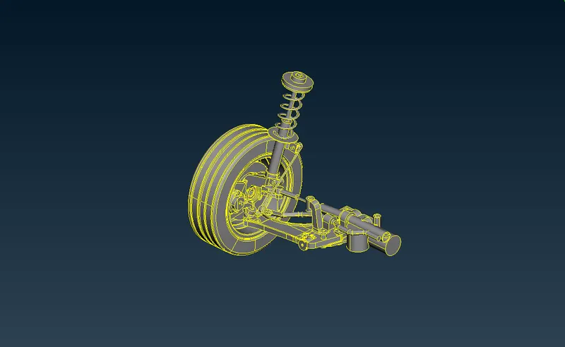
AIM: The main aim is to create volume mesh, surface mesh, Mid surface mesh and 1D mesh wherever required in the given Rear suspension
model using ANSA software and providing suitable connections using NASTRAN deck in ANSA software.
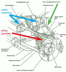
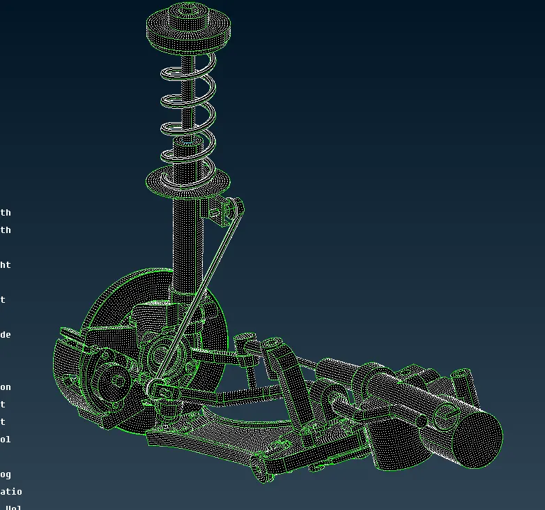
REAR SUSPENSION MODEL:
The suspension has been an essential component of automobiles as long as they have been in production. The rear suspension of a vehicle
performs the same general function as front suspension, but the specific construction is typically quite different. The ideal suspension for a vehicle
depends a lot on the vehicle's body style and performance requirements.
The most basic purposes of a suspension system are to prevent the body of a vehicle from hitting the ground and to keep the tires in contact with
the road.
Suspension is mechanically more complex for a pair of wheels that receives power from the engine. The suspension must be able to handle the
transfer of engine torque effectively to the wheels while resisting the rotational force of the driveshaft. In vehicles that have rear-wheel drive, the
rear suspension usually has more components than the front suspension.
The suspension for the first automobiles was similar to those used in horse-drawn carriages. These early suspension systems quickly proved
inadequate for the greater speeds than were possible with vehicles powered by internal combustion engines. One of the first major refinements in
the suspension of these vehicles was self-damping shock absorbers that dissipated the forces caused by the irregularities in road surfaces.
PROCEDURE: The main steps in this procedure are as follows
1] OPENING THE FILE.
2] PERFORMING THE GEOMETRIC CLEANUP AND TOPOLOGICAL CLEANUP.
3] SURFACE MESHING OF THE RIM USING TRAI ELEMENTS AND BATCH MESH PROCESS.
4] SURFACE MESHING OF THE TYRE USING TRAI ELEMENTS AND BATCH MESH PROCESS.
5] SURFACE MESHING REMAINING ELEMENTS OTHER THAN RIM AND TYRE.
1] OPENING THE FILE:
- After downloading the file open ANSA>>OK>>OPEN>>SELECT CAD FILE>>OK. This process is used to open a downloaded file in ANSA software.
2] PERFORMING THE GEOMETRIC CLEANUP AND TOPOLOGICAL CLEANUP:
- Generally, the topological clean up is carried out to stitch the unstitched cons and fill the unwanted cracks and holes manually.
- To perform IN TOPO MENU>> FACES>> TOPO>> SELECT THE MODEL>> MIDDLE MOUSE CLICK >>DONE.
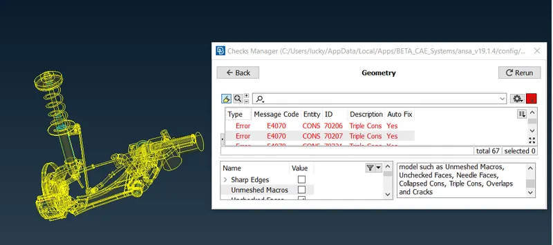
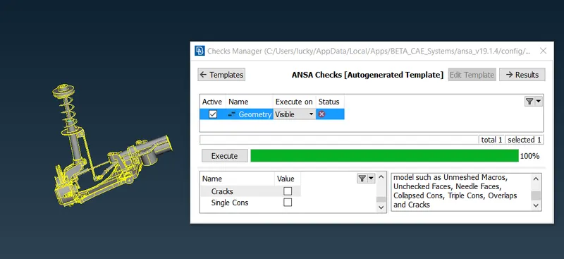
- Just like the topological cleanup is a manual process the automatic process to check the errors is known as the geometric cleanup.
- It is done to remove and eliminate unnecessary cons and hot points.
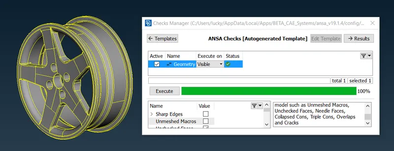
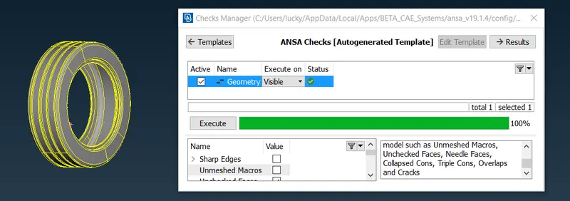
- The process for this step is TOOLS>> CHECKS>> GEOMETRY >> EXECUTE. below are the images related to this step.
3] SURFACE MESHING OF THE RIM USING TRAI ELEMENTS AND BATCH MESH PROCESS:
- Batch mesh is an automatic mesh generation process that consumes less time compared to manual meshing.
- Creating the new part in the modal browser will help us identifying the surface on which we have to Batch mesh. Below are some images related to this step.
- The batch mesh can be selected from the tools manager or by clicking CTRL+B.
- In TOOLS MANAGER>> BATCH MESH>> NEW>> MESHING SCENARIO>> SELECT THEM BY DOUBLE CLICK>> SELECT NEW PART WE CREATED IN MODEL BROWSER>> OK>> GIVE THE MESH PARAMETERS AND QUALITY CRITERIA>> RUN>> OK The mesh is generated. Below are some images related to this step.
- In solid meshing, we have to focus on curved surfaces. On these surfaces, we have to deploy the ortho trai mesh only as they will help us to get better mesh flow. using only normal trais will not give us the mesh flow we expect.
- In the above images while Batch meshing we can set the quality criteria and mesh parameters by double-clicking on untitled as shown above.
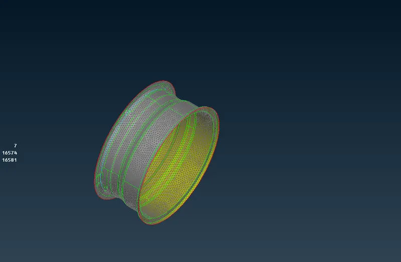
- After hitting on Run the software itself meshes the given component and saves the users lot of time as shown in the below images.
- As shown in the above images the surface meshing of the RIM component is completed using the Trai elements and Batch meshing Process.
4] SURFACE MESHING OF THE TYRE USING TRAI ELEMENTS AND BATCH MESH PROCESS:
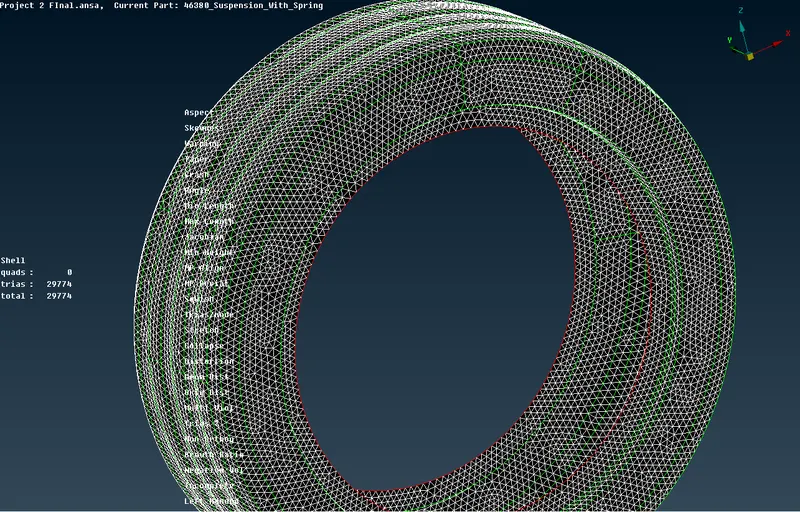
- A similar process is used to batch mesh the TYRE component as shown above. Below are the images related to tyre surface meshing.
5] SURFACE MESHING REMAINING ELEMENTS OTHER THAN RIM AND TYRE:
- The same procedure is used here as used for the rim and tyre below are the images.
LEARNING OUTCOMES:
- Basics of ANSA software
- Geometric cleanup
- Basics of topological corrections
- Basics of the Mesh Generation
- Surface meshing
- Learning about the types of mesh flows
- Creation of the volumetric mesh
- Basics of Unstructured mesh [Tetra mesh]
- Difference Between Surface meshing and Volume meshing
- Connections using RBE2 elements and seam weld.
- Importance of Preprocessing.
CONCLUSION:
Through this project, we can learn a lot of things and implement this experience in the upcoming challenges. This project will help us develop a
good understanding of the volume mesh, surface meshing, Tetra meshing, types of connections and basics of ANSA software. Thank you.