Week 1 Spur Gear Challenge
OBJECTIVES:
1. To carry out a structural analysis in spur gears using cast iron, cast steel, and cast bronze to obtain maximum stress, deformation, and intensity.
2. To compare the analysis results for three different cases and suggest the best one.
METHODOLOGY:
1. Material Assignment
The gears were assigned with Cast Iron ductile, Cast Steel, and Bronze Cast for the three different cases.
The important properties of these materials are listed in the table below.
Table 1. Properties of Materials
S.N. Material Young's Modulus Tensile Yield Tensile Ultimate Poisson's Ratio
pa Strength(pa) Strength(pa)
1. Cast Iron Ductile 1.71E11 3.44E08 5.48E08 0.275
2. Cast Steel 2.03E11 3.49E08 5.05E08 0.3
3. Bronze Cast 8E10 1.44E08 2.67E08 0.345
2. 3D Model import
The 3D model was imported from the design provided in .stp format.
3. Contacts and Joints
The faces of both the gears that would come into contact during the motion were identified, selected and a frictional contact was set up between them. Augmented Lagrangian was used as a formulation method to prevent the chattering and penetration of the tooth face. The interface was adjusted to make contact initially.
Revolute joints were applied to the inner face circle of both the gears to allow them to rotate about their axis. By selecting the body ground in the connection type, it was assured that joints were referenced with respect to fixed ground.
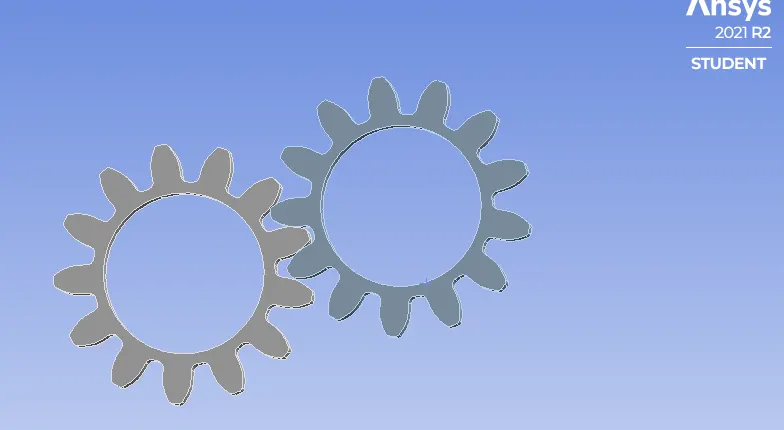
Fig: Contacts setup
4. Meshing
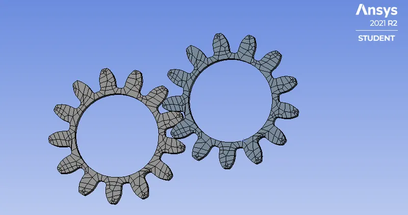
Element size was kept to 0.75 mm not to exceed the number limit in Academic Version. The adaptive sizing was turned off and the mesh was
provided with total of 5340 elements.
5. Loads and Constraints
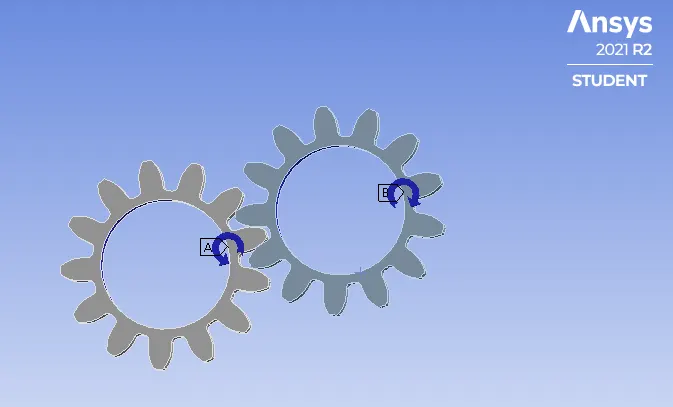
Anticlockwise rotation was given to the gear in left and a clockwise moment of 10 Nm was applied to the gear in the right through the revolute
joints assigned. The large deflection was turned on so that ANSYS will be able to account for the change of stiffness due to change in shape.
The anticlockwise rotation of 180 was divided into 6 steps, each of 30 degrees. For every time step, the further settings were made the same.
RESULTS
After all the boundary conditions were applied, the results in form of equivalent stress, total deformation, and stress intensity were analyzed for all the cases. The contours and the graph for each of the values are listed below.
a. Cast iron ductile
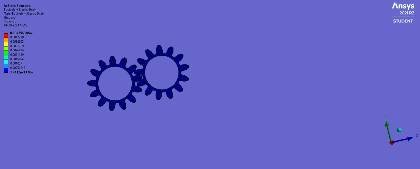
Fig:Equivalent Stress
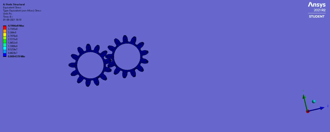
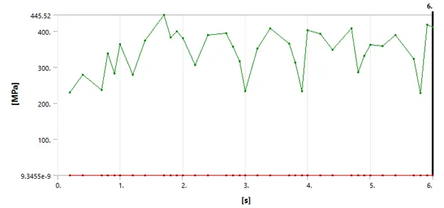
Fig:Equivalent Elastic Strain
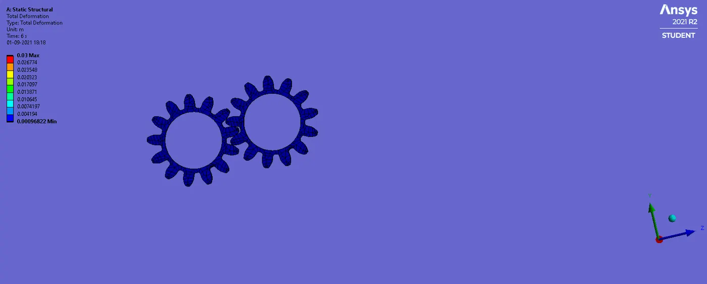
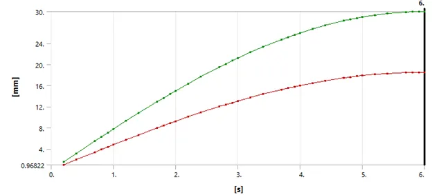
Fig:Total Deformation
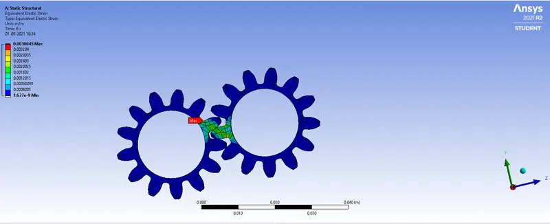
Fig: Location for possible fracture
b.Cast Steel
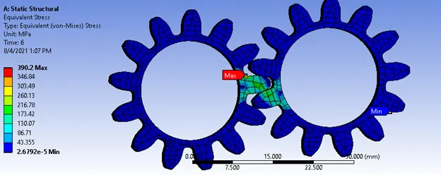
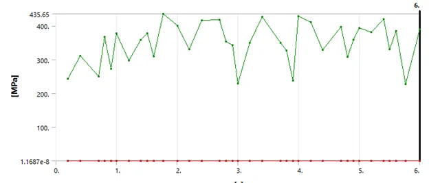
Fig:Equivalent Stress
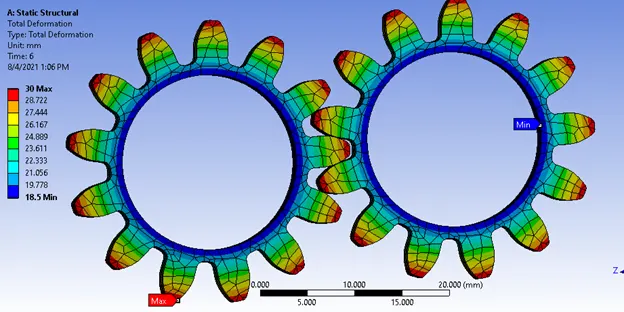
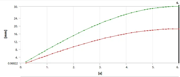
Fig:Total Deformation
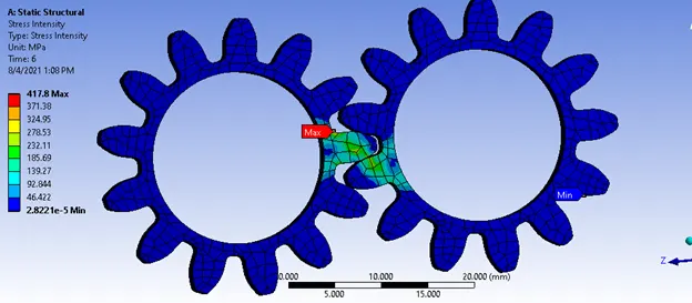
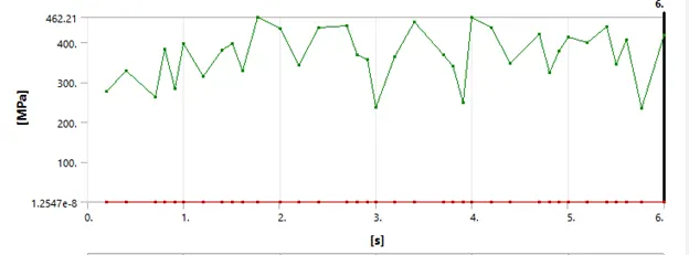
Fig:Stress Intensity
c. Bronze Cast
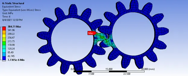
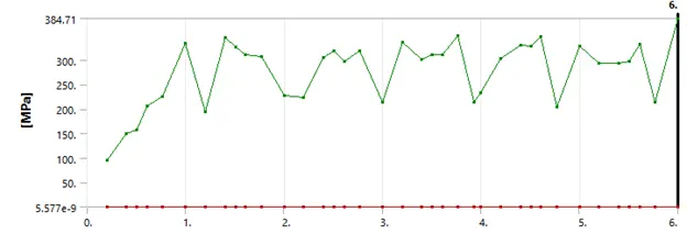
Fig:EquivalentStress
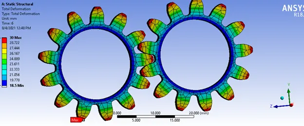
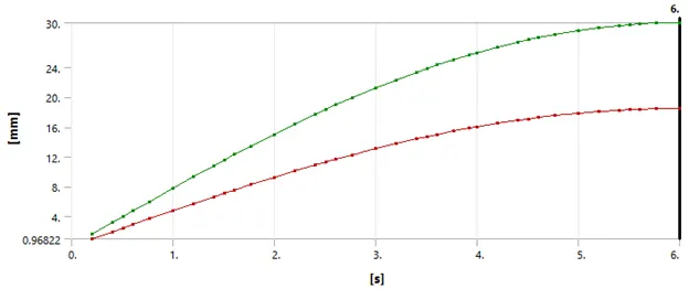
Fig:Total Deformation
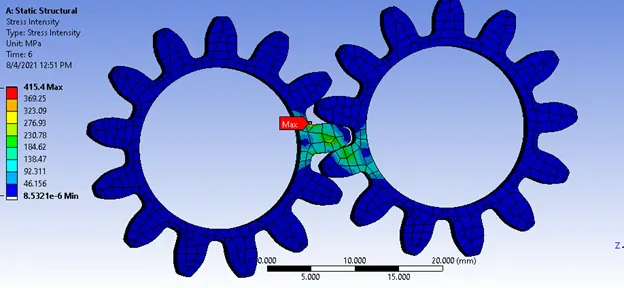
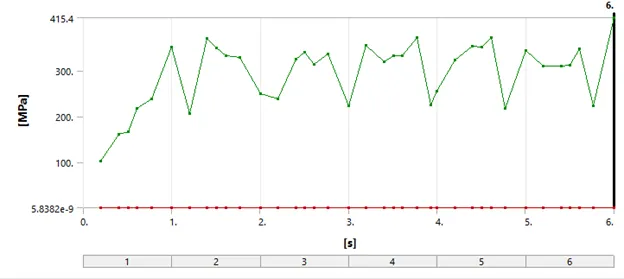
Fig:Stress Intensity
Summary of the results:
|
Material |
Stress (Max) |
Deformation (Max) |
Stress Intensity(Max) |
|
Cast Steel |
435.65 MPa |
30 mm |
462.21 MPa |
|
Cast Iron |
422.37 MPa |
30 mm |
445.52 MPa |
|
Cast Bronze |
384.71 MPa |
30 mm |
415.14 MPa |
ANALYSIS:
For all the three materials, the maximum stress was observed in the root of the teeth. Simlarly, the stress intensity measured was also found to be
maximum in the same region. The deformation is however found to be similar for all the cases. The graph of the output components with respect to
time was observed and the values are noted in the table above. The results can be written in brief as:
Equivalent Stress: Cast Steel>Cast Iron> Cast Bronze
Stress Intensity: Cast Steel>Cast Iron> Cast Bronze
From the results, it is observed that the equivalent stress and the stress intensity is maximum for cast steel and minimum for the cast bronze. The
smaller values of stress intensity assists the part in achieving a longer life. Hence, from the analysis, it can be considered that cast bronze is the
typical material for the spur gears due to the lower values of equivalent stress and stress intensity experienced by the material for the same
boundary conditions.