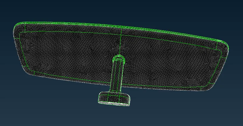
Week- 5 - Solid meshing
AIM:
For the given Rearview mirror component, check for the geometrical errors and mesh the Surfaces with the given 2D element Quality
criteria and create a volume mesh with good surface quality (i.e. There should not and kinks and dips on the surface of the component).
OBJECTIVE:
To check for the geometrical errors for the given component and mesh with the given element Quality criteria. Use tetra elements to
model the component and finally create volume mesh for the given component.
QUALITY CRITERIA:
To mesh the Surfaces with the gen 2D element Quality criterias given below.
|
S.No |
Quality Criteria |
Value |
|
1 |
Target/Average length |
1 |
|
2 |
Minimum Length |
0.5 |
|
3 |
Maximum Length |
2 |
Note: For 2D Elements, Only check for Min length and Max length errors.
To mesh the Volumes defined in the model and check for the below quality after Volume meshing.
|
S.No |
Quality Criteria |
Value |
|
1 |
Tet collapse |
0.2 |
Note: For 3D Elements, Only check Tet Collapse errors.
PROCEDURE:
1.First, we want to open it then we import the CAD model by using the File>open option and select the rearview_mirror.ansa hence the model
will appear in the graphical area that is shown below,
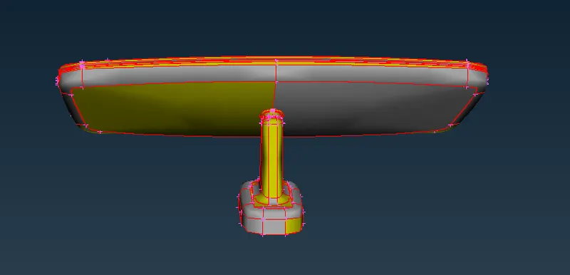
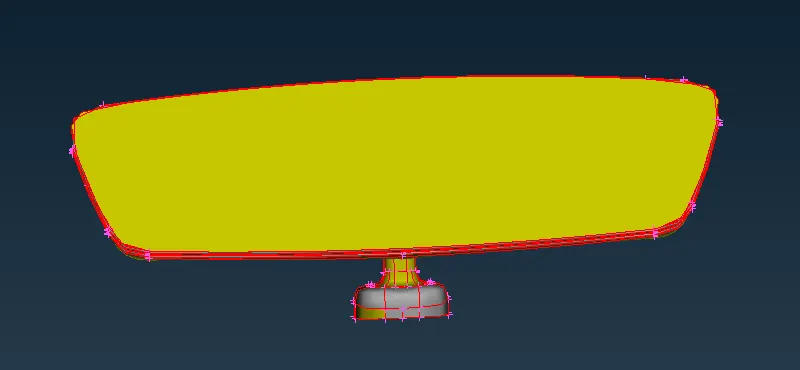
Fig: Rearview Mirror open model
2.After that, we perform TOPO using the topo option present in the Faces section of the TOPO Module the selection process is shown as below,
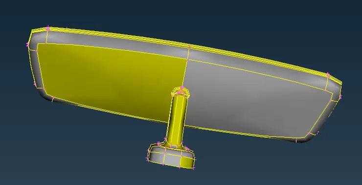
Fig: Topo option
3.Now the topo operation is done and all the free surfaces are stiched with each other and that is shown as below,
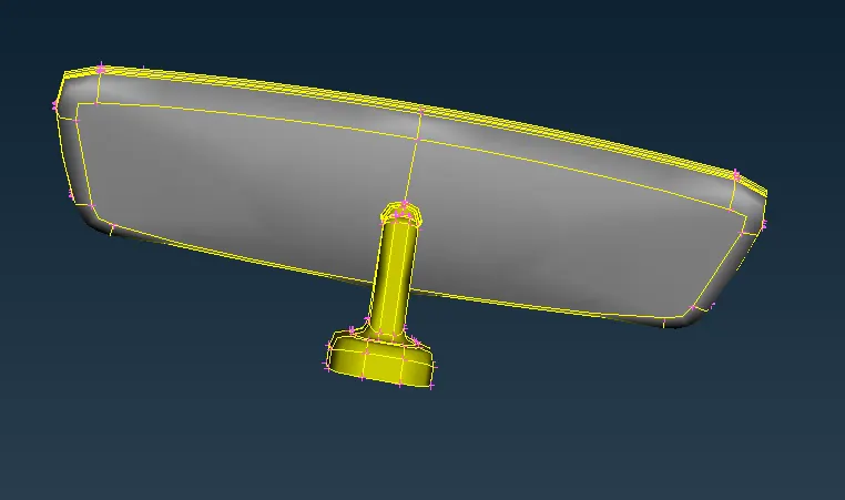
Fig: Topo model
4.Then perform the orient option in Faces module to modifies the orientation of the faces they are shown as below,
Fig: Orient option
5.On opening the CAD geometry into the ANSA database, we provide perimeter length to the whole component for visualization of the curve &
edges and also refine the CAD geometry. For this, we go to the Mesh Module and go to the length option present in the section of the perimeter
and provide the perimeters length and macros length as 1 as shown in the image given below,
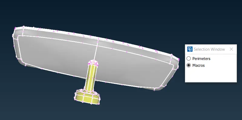
Fig: Length option
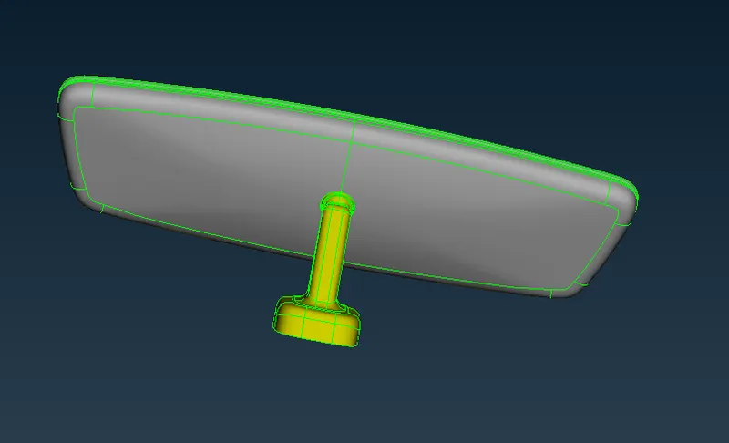
Fig: Length Perimeters
6.Therefore the length of perimeter and the macros is assigned and they are shown as below,
Fig: Assigned Length
7.Now we check for the geometric errors using the check geometry option present in the tools option as shown in the image given below,
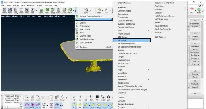
Fig: Geometry option
8.In ANSA software there certain kind of tools used for geometry clean up, meshing, and different types of the solver to define certain problems.
Initially, the CAD model should import into the software and check for geometry any error found! there are certain types of errors like triple cons,
single cons, unchecked faces, convex cons, etc. Here also we obtain these kinds of geometrical errors are observed in this model they are shown
as below,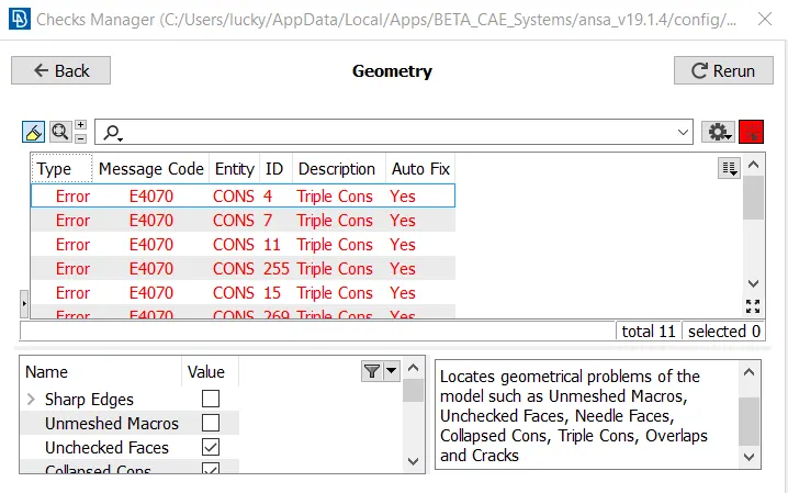
Fig: Geometry Cleanup
9.These errors can fix automatically and also manually. In this model, some errors are fixed by identifying the error and clear that error by
untoggle the line and stitch the surfaces again or delete the unwanted surfaces present in that model manually they are shown as below,
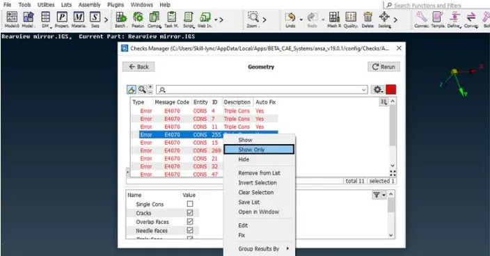
Fig: Geometry Cleanup Manually fix
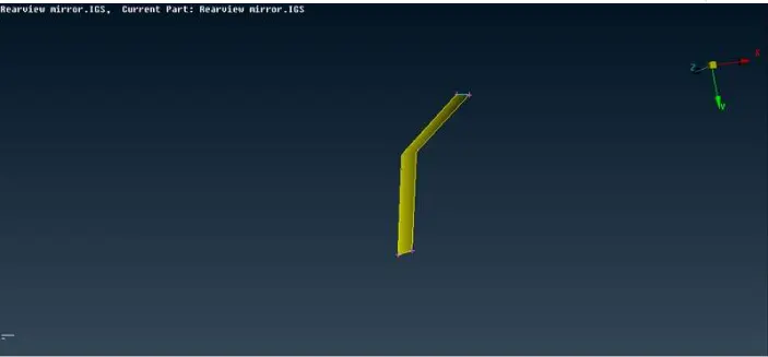
Fig: Geometry Cleanup Manually fix
10.These errors can fix automatically and also manually. In this model some errors are auto-fixed and the list of errors is shown below,
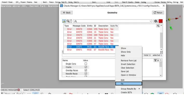
Fig: Geometry Cleanup Automatically fixed
11.The errors are fixed by both automatic and manual methods now the geometry is cleared from geometric errors and they proceed for mid
surface operation. The geometry cleanup image is shown below,
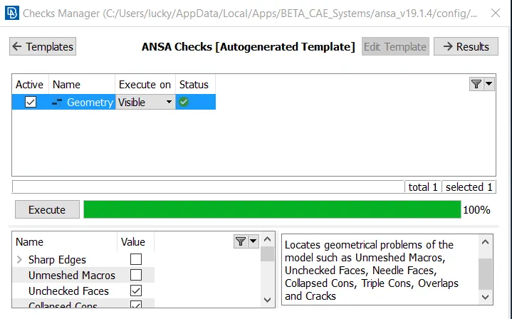
Fig: Geometry Cleanup
2-D MESHING:
1.Now we want to proceed with the model for 2D meshing with some quality criteria that are given by an instructor. The component is split into
four parts according to the property and proceed for 2D tetra meshing, the four different components in the model is shown as below,
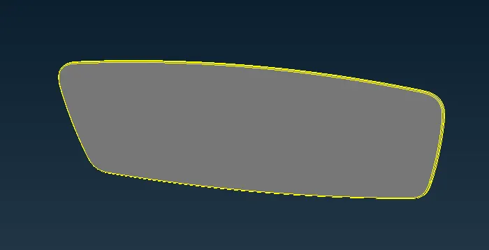
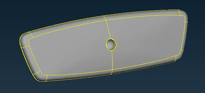
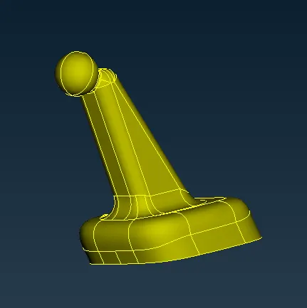
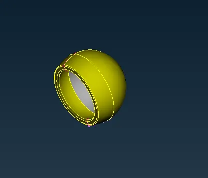
Fig: Four components
2.There are some critical quality parameters required for meshing the component that is given in quality criteria.Therefore we want to enter all
mesh parameters, quality criteria in the mesh parameters, and quality criteria options present in the utilities tab as shown in the images given
below,
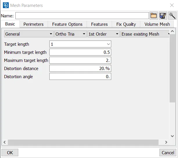
Fig: Mesh parameters
3.In mesh parameters, we set the min, max, and target element length of the mesh and we provide the mesh type as tria mesh as shown in the
image given below.
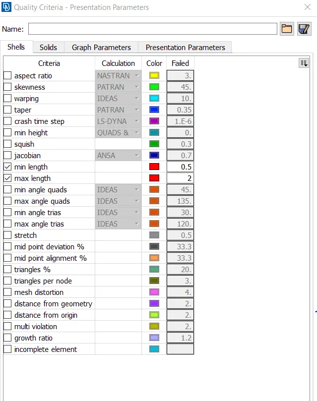
Fig: Quality Criteria
4.To enable the total percentage of trias and the quantity of the off elements we are selecting the elements% in presentation parameters. After
that select, all details and click apply to obtain the total values of elements and trias percentage of the total model. A selection process is shown as
below,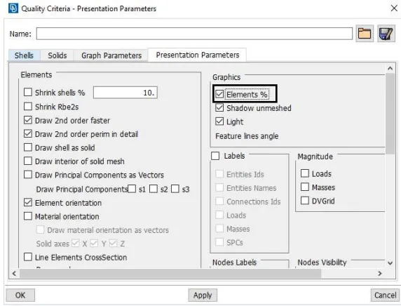
Fig: Presentation parameters
5.To select Spot Mesh with element type as ortho tria and select the fillet area and do tetra mesh. The selection process is shown as below,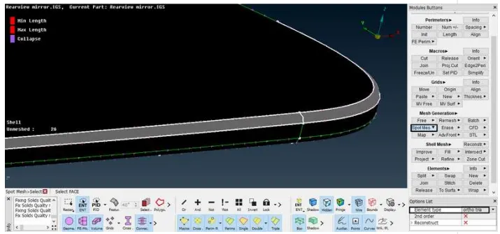
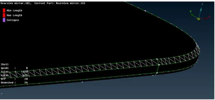
Fig: Ortho tria option
6.To select Spot Mesh with element type as tria and select the normal Surface and do tetra mesh. The selection process is shown as below,
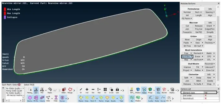
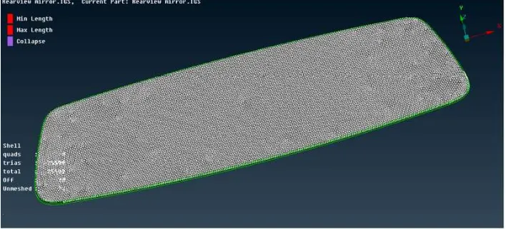
Fig: Tria option
7.Therefore all the components have meshed separately with the element type as trias and ortho trias. The meshed components are shown as
below,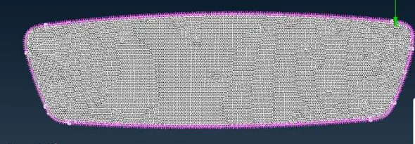
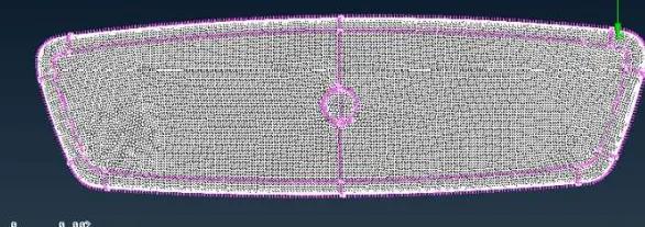
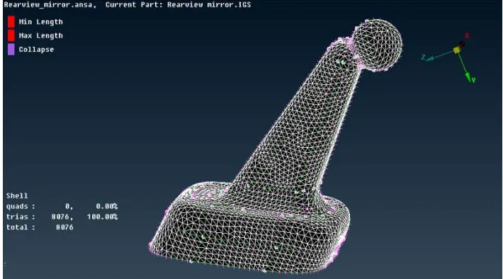
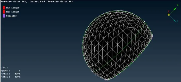
Fig: 2D meshed components
8.We can now mesh the component using tria elements for flat surfaces and ortho tria elements for curved surfaces using the spot mesh options
present in the mesh generation section of the mesh module as shown in the image given below,
After done the meshing as per the quality criteria.
9.We need to eliminate all the quality errors caused by using reconstruct option present in the shell mesh section of the mesh module We obtain
the fully meshed model with zero quality errors as shown in the image given below,
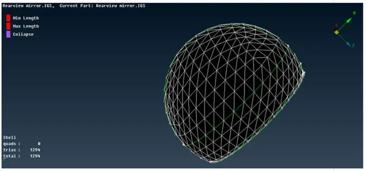
Fig: 2D meshed component
VOLUME MESH:
1.After, that we provide the quality criteria for the tetra mesh as shown in the image given below.
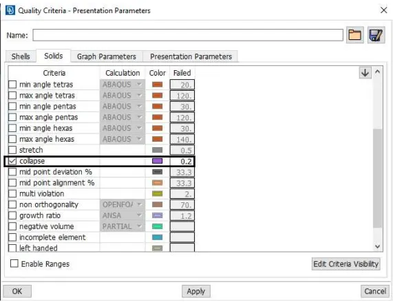
Fig: Quality Criteria
2.Now we have to define a volume before we proceed for volumetric meshing of the component. We define the volume for the component using
the define option present in the volumes section of the volume mesh module. A selection process is shown as below,
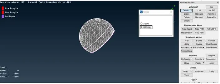
Fig: Define option
3.Now we want to create the solid property while selecting the define option the property help tab will appear right click on that
tab>new>PSOLID and denote the SOLID property the selection process is shown as below,
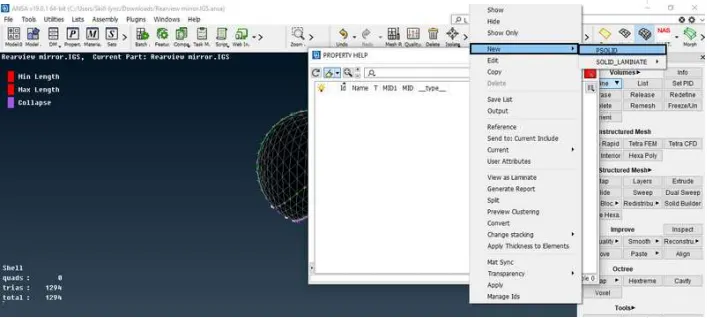
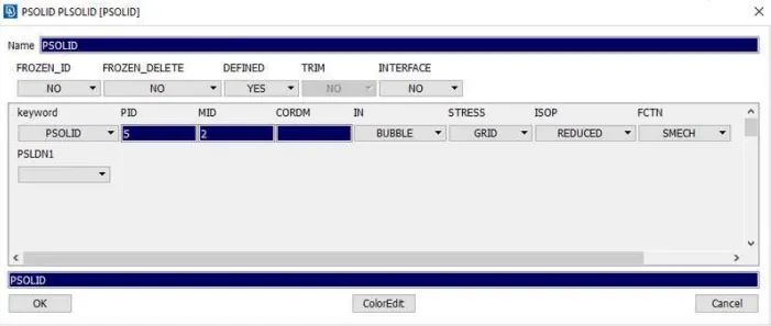
Fig: Solid Property
4.Now go to the Volumes>list option and check the defined volume.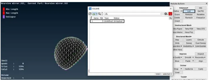
Fig: List option
5.To create the volume tetra mesh for that component select the unstructured mesh module and click meshing options like tetra rapid, tetra FEM,
etc. The other way to obtain volume mesh is to click the list option and right-click the>undefined unmeshed>remesh option a selection
process is shown as below,
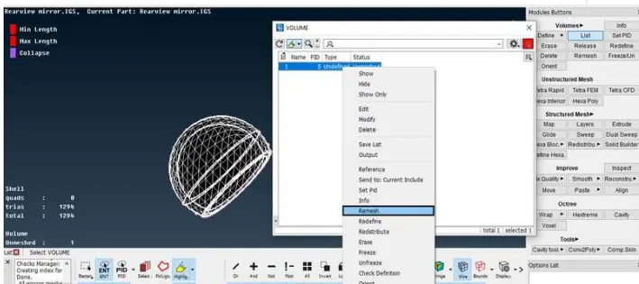
Fig: Unstructured Mesh
6.After that select tetra rapid volume mesh type then click ok to obtain the volume mesh for that component. The volume mesh type is shown as
below,
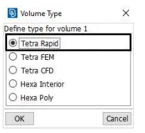
Fig: Mesh Type
7.Hence the Volume mesh is created for that component but off elements are shown in volume mesh that represents the tet collapse that has
appeared in that model so we want to clear the quality criteria for volume tetra mesh. The obtained volume tetra mesh with off elements is shown
as below,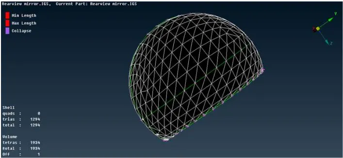
Fig: Volume Mesh
8.To eliminate all other off elements like tet collapse by using MV Free option. They are shown as below,
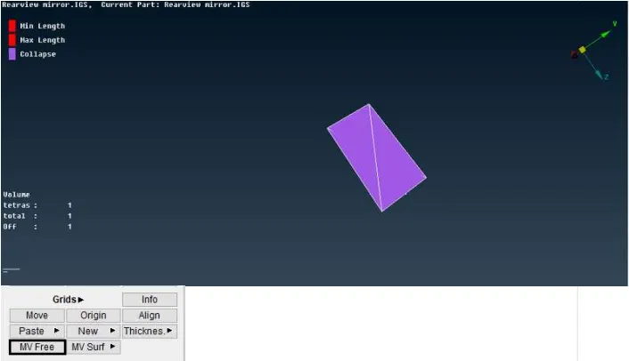
Fig: MV Free option
9.Now all the off elements in the volume mesh are cleared and they are shown as below,
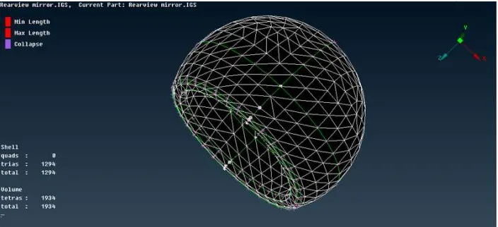
Fig: Volume Tetra Mesh
10.Similarly, the volume tetra mesh is generated for all other components and the off elements are eliminated by using MV free option and the
volume tetra mesh of the rearview mirror is shown as below,
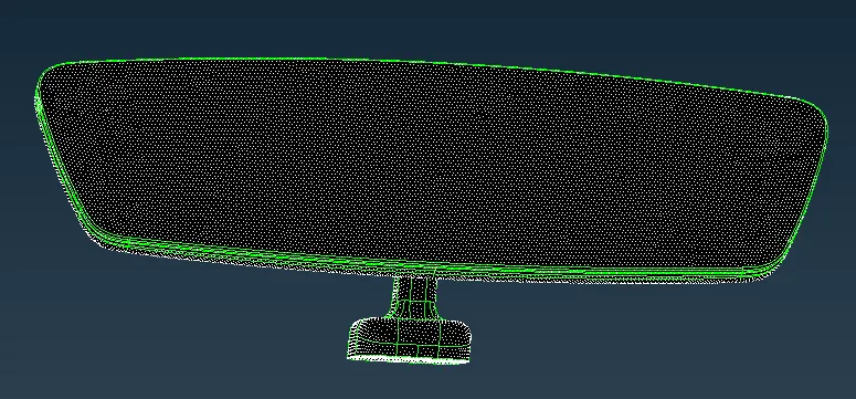
Fig: Rearview Mirror using Tetra Mesh
LEARNING OUTCOMES:
1.Learned to mesh the given component using only tria and ortho tria elements.
2.Learned to defining a volume and applying volume mesh or tetra mesh over selected volume using Unstructured mesh (Tetra Rapid & Tetra FEM)
and clearing errors such as kink, dip, and tet collapse elements.
CONCLUSION:
Therefore a given Rearview Mirror model is checked for the geometrical errors and meshed with element type as ortho tria & tria as per given
quality criteria. After meshing defined the volume and meshed the volume by using an unstructured mesh with the type of Tetra Rapid & Tetra
FEM. The off elements also eliminated and the quality criteria are cleared in this model.