week-11 Joint creation and Demonstration
Aim:
The aim of the challenge is to create the joints by using the CONSTRAINED_JOINTS keywords to demonstrate revolute,spherical,
cylindrical and translational joints between the two rigid bodies and two deformable bodies and simulate the joints in LS-Dyna.
Procedure:
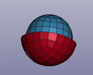
1. Spherical joint(Rigid Body):
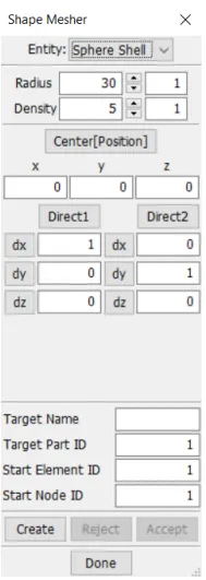
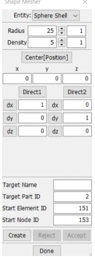
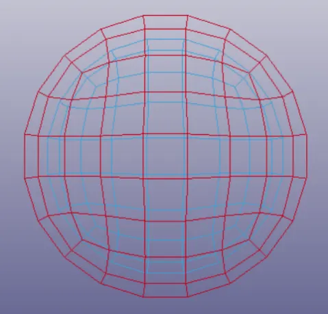
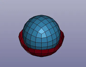
1.Firstly create two spherical shell elements by going to the mesh and element tab bar and click on the shape mesher.Under the shape mesher
change the entity into the sphere shell and create two shell spheres with two different radius.
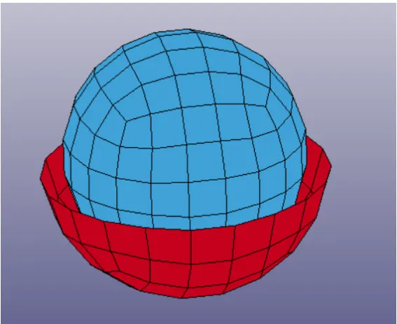
2.Now delete the top elements of the outer shell sphere by selecting the element tool tab and clicking element editing option.Now select the top
elements of the outer shell sphere and delete them.
3.Now create a rigid material card and a section shell card as shown in the below fig.
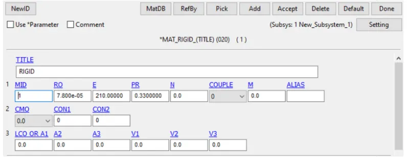
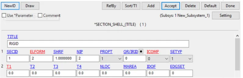
4.Now assign the both above created cards to the both created sphere shell parts as shown in below.
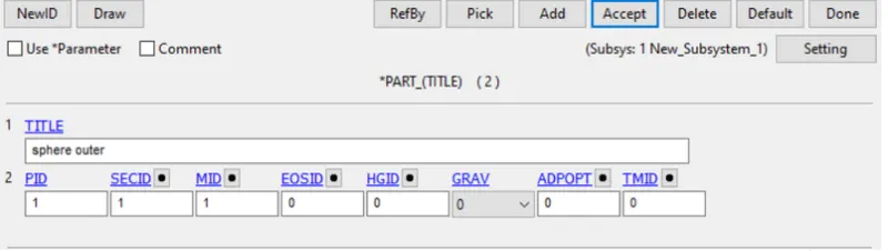
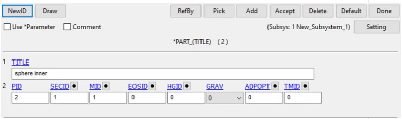
5.In order to create a spherical joint we need to create two nodes so that 1 node is assigned to one part and the next is assigned to other
part.Under element tool tab click on node edit option and create two nodes that has same co-ordinates.
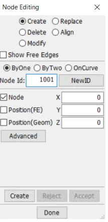
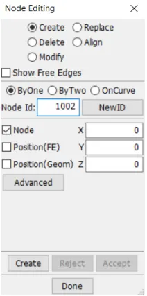
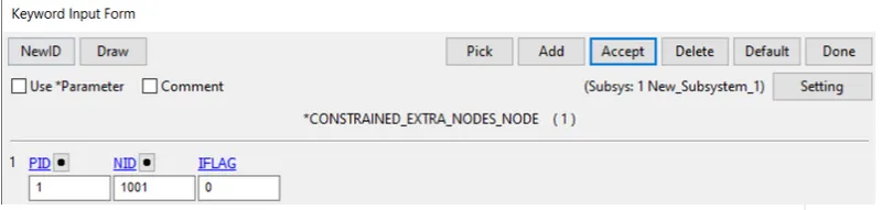
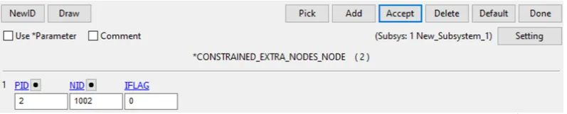
6.Open the keyword manager and check the all button.Under the CONSTRAINED keyword select the EXTRA_NODE card.select the node and assign
it to appropriate part number.
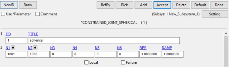
7.Now under the constrained keyword select the JOINT_SPHERICAL card and assign the node for the joint.
8.Now create a initial velocity rigid body card and assign the velocity as shown in below.

9.Now under the CONTROL keyword select the TERMINATION card and give the end time.

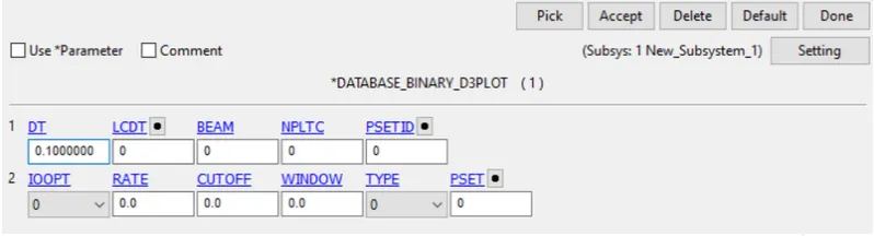
10.Create a e DATABASE keyword select the D3PLOT card.
11.At last run the simulation.
2. Spherical joint(Deformable Body):
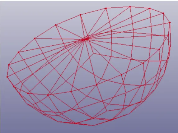
1.Firstly create two spherical shell elements by going to the mesh and element tab bar and click on the shape mesher.Under the shape mesher
change the entity into the sphere shell and create two shell spheres with two different radius.
2.Now delete the top elements of the outer shell sphere by selecting the element tool tab and clicking element editing option.Now select the top
elements of the outer shell sphere and delete them.
3.Now create a rigid material card and a section shell card as shown in the below fig.
4.Now assign the both above created cards to the both created sphere shell parts as shown in below.
5.In order to create a spherical joint we need to create two nodes so that 1 node is assigned to one part and the next is assigned to other
part.Under element tool tab click on node edit option and create two nodes that has same co-ordinates.
6.:Now open the create entity box and select the constrain nodal rigid body for both the parts.
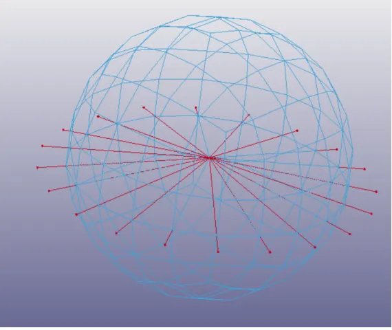
7.Open the keyword manager and check the all button.Under the CONSTRAINED keyword select the EXTRA_NODE card.select the node and assign
it to appropriate part number.
8.Now under the constrained keyword select the JOINT_SPHERICAL card and assign the node for the joint.
9.Now create a initial velocity rigid body card and assign the velocity as shown in below.
10.Now under the CONTROL keyword select the TERMINATION card and give the end time.
11.Create a e DATABASE keyword select the D3PLOT card.
12.At last run the simulation.
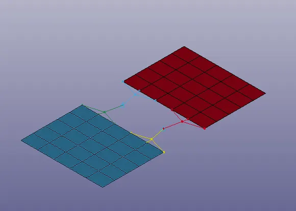
3. Revolute joint(Rigid Body):
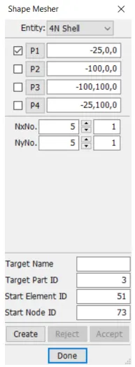
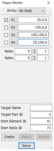
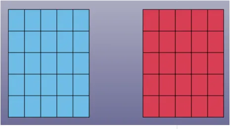
1.Firstly create two 4N shell elements by going to the mesh and element tab bar and click on the shape mesher.Under the shape mesher
change the entity into the 4N shell and create two bodies as shown.
2.Now create a rigid material card and a section shell card as shown in the below fig.
3.Now assign the both above created cards to the both created sphere shell parts as shown in below.
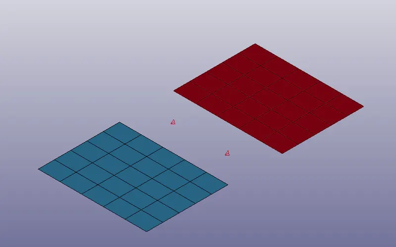
4.In order to create a revolute joint we need to create four nodes so that 2 node is assigned to one part and the next two is assigned to other
part.Under element tool tab click on node edit option.
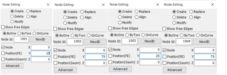
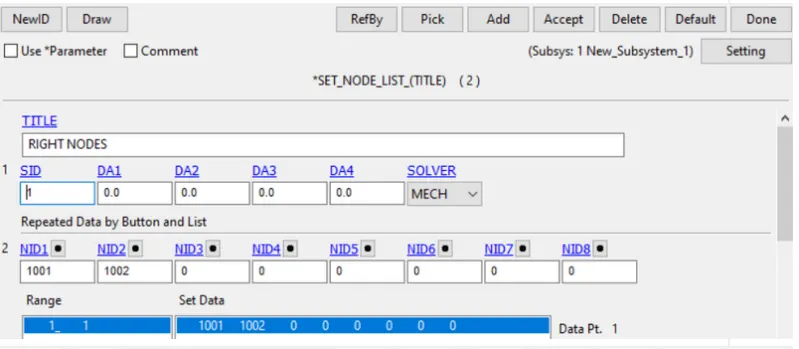
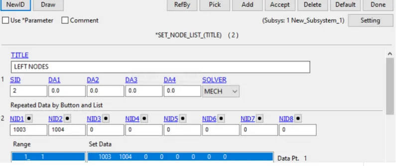
5.Create new node sets, where nodes 1001 and 1002 belong to one node-set, and nodes 1003 and 1004 belong to another node-set.The node sets
can be created through Create Entity>Set Data>*SET_NODE>Create option.
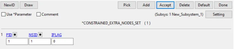
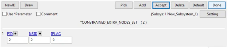
6.Open the keyword manager and check the all button.Under the CONSTRAINED keyword select the EXTRA_NODE card.select the node and assign
it to appropriate part number.
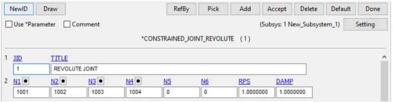
7.Now under the constrained keyword select the JOINT_REVOLUTE card and assign the node for the joint.
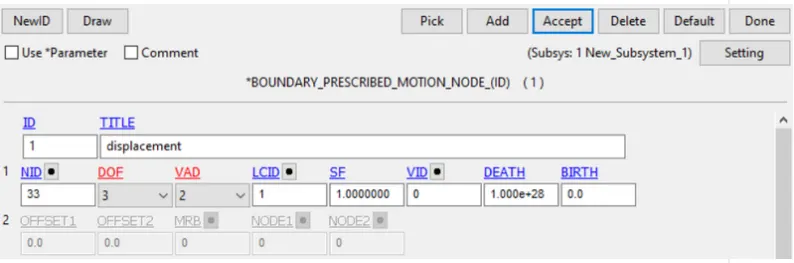
8.BOUNDARY PRESCRIBED MOTION NODE:
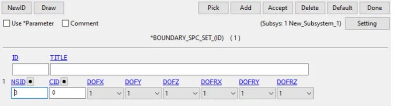
9.BOUNDARY SPC_SET:
10.Now under the CONTROL keyword select the TERMINATION card and give the end time.
11.Create a e DATABASE keyword select the D3PLOT card.
12.At last run the simulation.
4. Revolute joint(Deformable Body):
1.Firstly create two 4N shell elements by going to the mesh and element tab bar and click on the shape mesher.Under the shape mesher
change the entity into the 4N shell and create two bodies as shown.
2.Now create a rigid material card and a section shell card as shown in the below fig.
3.Now assign the both above created cards to the both created sphere shell parts as shown in below.
4.In order to create a revolute joint we need to create four nodes so that 2 node is assigned to one part and the next two is assigned to other
part.Under element tool tab click on node edit option.
5.Create new node sets, where nodes 1001 and 1002 belong to one node-set, and nodes 1003 and 1004 belong to another node-set.The node sets
can be created through Create Entity>Set Data>*SET_NODE>Create option.
6.Now open the create entity box and select the constrain nodal rigid body for both the parts.
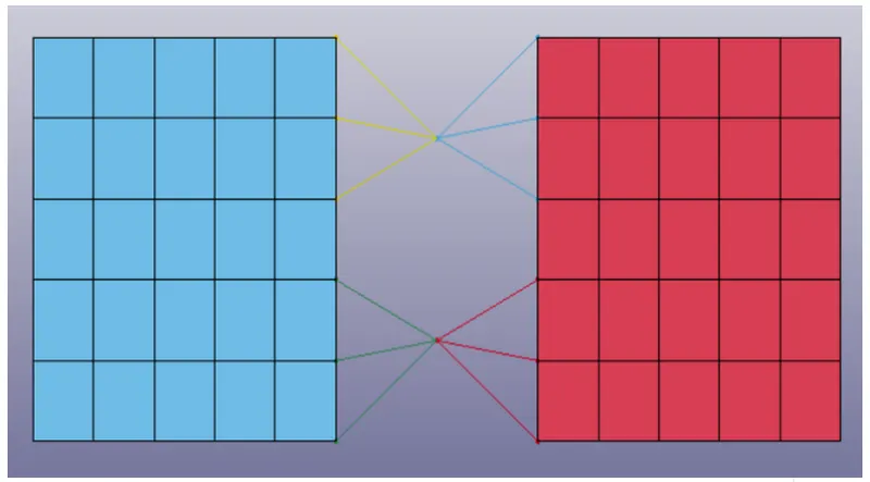
7.Open the keyword manager and check the all button.Under the CONSTRAINED keyword select the EXTRA_NODE card.select the node and assign
it to appropriate part number.
8.Now under the constrained keyword select the JOINT_REVOLUTE card and assign the node for the joint.
9.BOUNDARY PRESCRIBED MOTION NODE:
10.BOUNDARY SPC_SET:
11.Now under the CONTROL keyword select the TERMINATION card and give the end time.
12.Create a e DATABASE keyword select the D3PLOT card.
13.At last run the simulation.
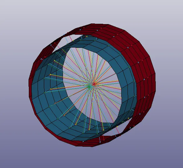
5. Cylindrical joint(Rigid Body):
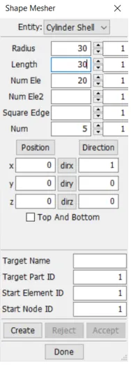
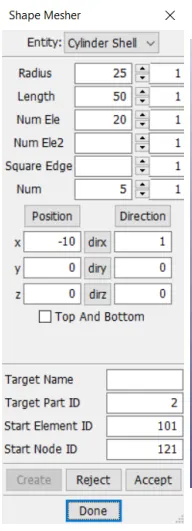
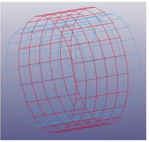
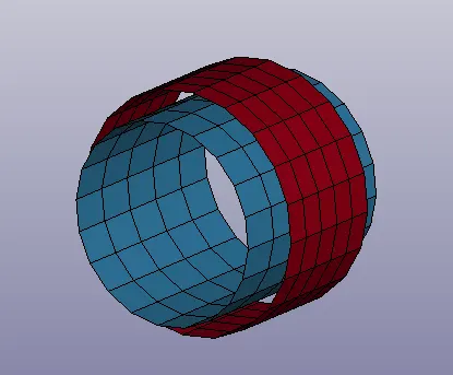
1.Firstly create two cylindrical shell elements by going to the mesh and element tab bar and click on the shape mesher.Under the shape mesher
change the entity into the cylindrical shell and create two shell cylinders with two different radius.
2.Now create a rigid material card and a section shell card as shown in the below fig.
3.Now assign the both above created cards to the both created sphere shell parts as shown in below.
4.In order to create a spherical joint we need to create two nodes so that 1 node is assigned to one part and the next is assigned to other
part.Under element tool tab click on node edit option and create two nodes that has same co-ordinates.
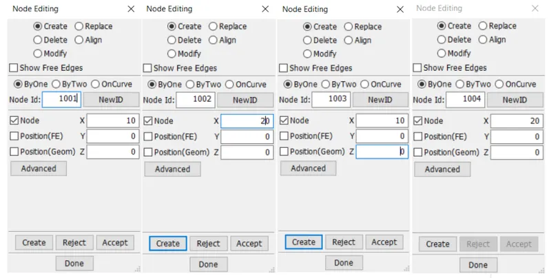
5. Create new node sets, where nodes 1001 and 1002 belong to one node-set, and nodes 1003 and 1004 belong to another node-set.The node
sets can be created through Create Entity>Set Data>*SET_NODE>Create option.
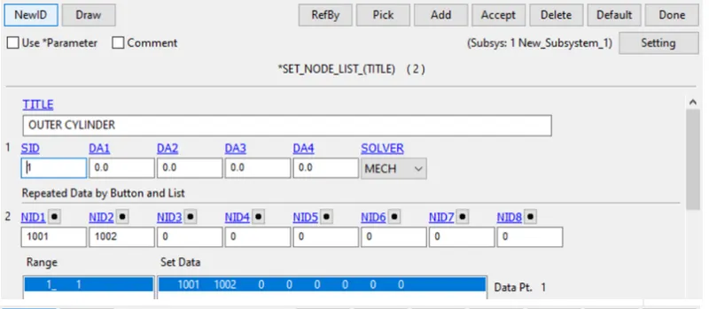
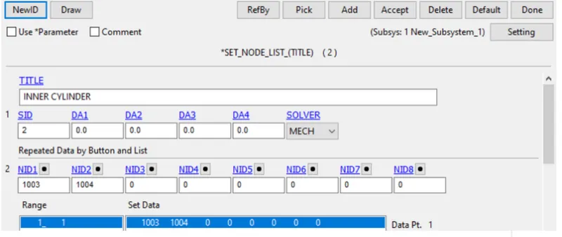
6.Open the keyword manager and check the all button.Under the CONSTRAINED keyword select the EXTRA_NODE card.select the node and assign
it to appropriate part number.
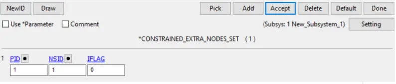
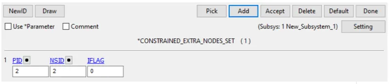
7.Now under the constrained keyword select the JOINT_CYLINDRICAL card and assign the node for the joint.
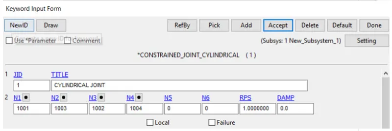
8.Now create a initial velocity rigid body card and assign the velocity as shown in below.
9.Now under the CONTROL keyword select the TERMINATION card and give the end time.
10.Create a e DATABASE keyword select the D3PLOT card.
11.At last run the simulation.
6. Cylindrical joint(Rigid Body):
1.Firstly create two cylindrical shell elements by going to the mesh and element tab bar and click on the shape mesher.Under the shape mesher
change the entity into the cylindrical shell and create two shell cylinders with two different radius.
2.Now create a rigid material card and a section shell card as shown in the below fig.
3.Now assign the both above created cards to the both created sphere shell parts as shown in below.
4.In order to create a spherical joint we need to create two nodes so that 1 node is assigned to one part and the next is assigned to other
part.Under element tool tab click on node edit option and create two nodes that has same co-ordinates.
5. Create new node sets, where nodes 1001 and 1002 belong to one node-set, and nodes 1003 and 1004 belong to another node-set.The node
sets can be created through Create Entity>Set Data>*SET_NODE>Create option.
6.Open the create entity manager and create constrain nodal rigid bodies for those points.
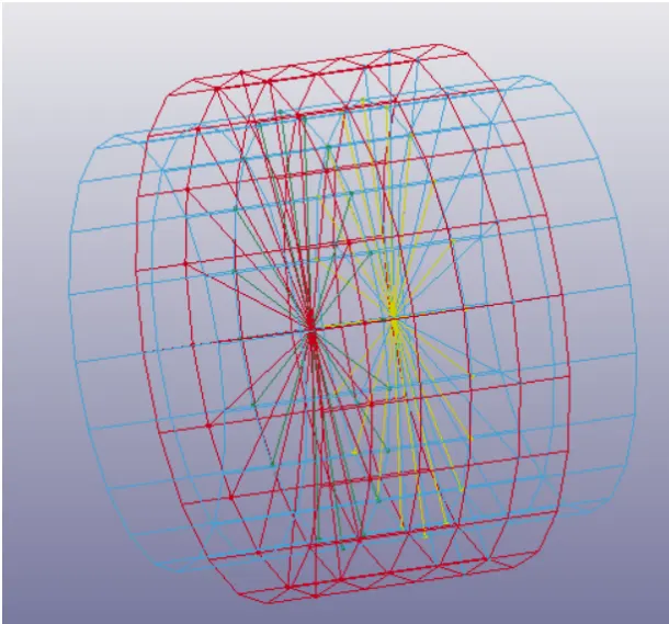
7.Open the keyword manager and check the all button.Under the CONSTRAINED keyword select the EXTRA_NODE card.select the node and assign
it to appropriate part number.
8.Now under the constrained keyword select the JOINT_CYLINDRICAL card and assign the node for the joint.
9.Now create a initial velocity rigid body card and assign the velocity as shown in below.
10.Now under the CONTROL keyword select the TERMINATION card and give the end time.
11.Create a e DATABASE keyword select the D3PLOT card.
12.At last run the simulation.
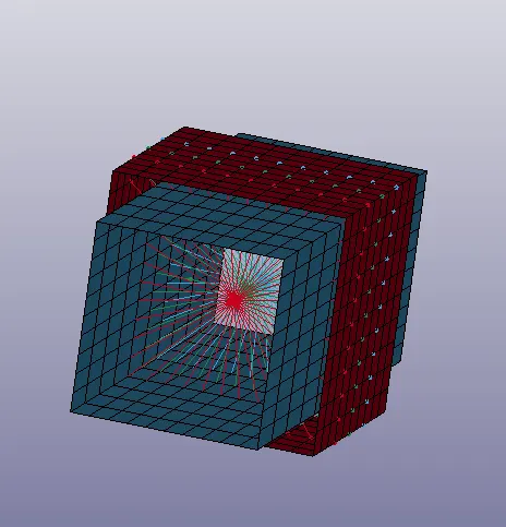
7. Tranlational joint(Rigid Body):
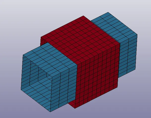
1.Firstly create two translational shell elements by going to the mesh and element tab bar and click on the shape mesher.Under the shape mesher
change the entity into the translational shell and create two shell as shown below.
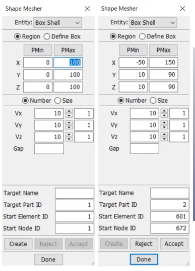
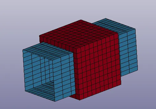
2.Now create a rigid material card and a section shell card as shown in the below fig.
3.Now assign the both above created cards to the both created sphere shell parts as shown in below.
4.In order to create a spherical joint we need to create two nodes so that 1 node is assigned to one part and the next is assigned to other
part.Under element tool tab click on node edit option and create two nodes that has same co-ordinates.
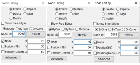
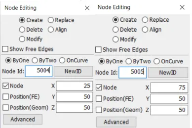
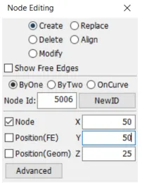
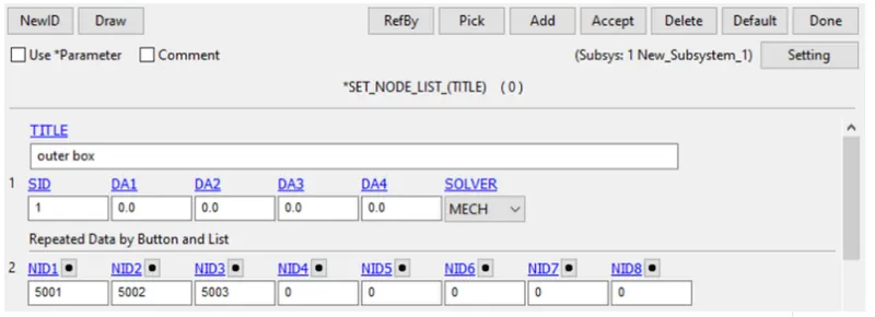
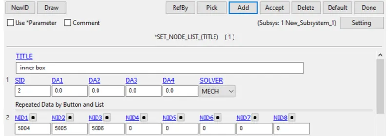
5. Create new node sets, where nodes 1001 and 1002 belong to one node-set, and nodes 1003 and 1004 belong to another node-set.The node
sets can be created through Create Entity>Set Data>*SET_NODE>Create option.
6.Open the keyword manager and check the all button.Under the CONSTRAINED keyword select the EXTRA_NODE card.select the node and assign
it to appropriate part number.
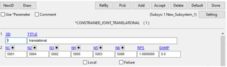
7.Now under the constrained keyword select the JOINT_TRANSLATIONAL card and assign the node for the joint.
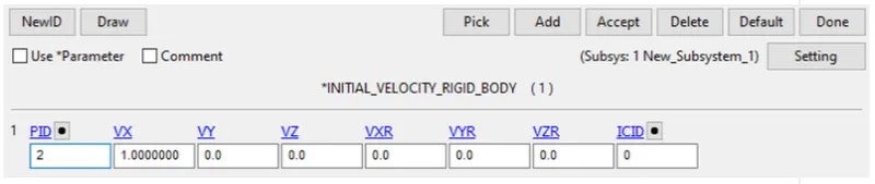
8.Now create a initial velocity rigid body card and assign the velocity as shown in below.
9.Now under the CONTROL keyword select the TERMINATION card and give the end time.
10.Create a e DATABASE keyword select the D3PLOT card.
11.At last run the simulation.
8. Tranlational joint(Deformable Body):
1.Firstly create two translational shell elements by going to the mesh and element tab bar and click on the shape mesher.Under the shape mesher
change the entity into the translational shell and create two shell as shown below.
2.Now create a rigid material card and a section shell card as shown in the below fig.
3.Now assign the both above created cards to the both created sphere shell parts as shown in below.
4.In order to create a spherical joint we need to create two nodes so that 1 node is assigned to one part and the next is assigned to other
part.Under element tool tab click on node edit option and create two nodes that has same co-ordinates.
5.:Open the create entity manager and create constrain nodal rigid bodies for those points
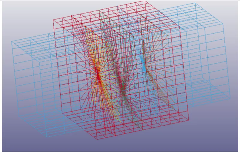
6. Create new node sets, where nodes 1001 and 1002 belong to one node-set, and nodes 1003 and 1004 belong to another node-set.The node
sets can be created through Create Entity>Set Data>*SET_NODE>Create option.
7.Open the keyword manager and check the all button.Under the CONSTRAINED keyword select the EXTRA_NODE card.select the node and assign
it to appropriate part number.
8.Now under the constrained keyword select the JOINT_TRANSLATIONAL card and assign the node for the joint.
9.Now create a initial velocity rigid body card and assign the velocity as shown in below.
10.Now under the CONTROL keyword select the TERMINATION card and give the end time.
11.Create a e DATABASE keyword select the D3PLOT card.
12.At last run the simulation.
Animation files:
Joints between rigid bodies:
revolute joint:
cylindrical joint:
translational joint:
spherical joint:
Joints between deformable bodies:
revolute joint:
cylindrical joint:
translational joint:
spherical joint:
Conclusion:
- The necessary keyword files are created for joints between rigid bodies such as spherical, revolute, translational, cylindrical joints using
constrained_extra_nodes and constrained_joint tools. - The necessary keyword files are created for joints between deformable bodies such as spherical, revolute, translational, cylindrical joints using constrained_nodal_rigid_body(CNRB) and constrained_joint tools.
- Finally ran the simulation and animation files were above.