Week 4 -Wire Bending Challenge
Objective:
For the given model we have to perform an analysis to simulate the bending of a wire in ANSYS by using the materials as Copper Alloy
(Non Linear), Aluminium Alloy (Non Linear) and Magnesium Alloy ( Non Linear) for the wire alone.
Procedure:
1.Open the ANSYS workbench in the system.
2.After opening the workbench,double click on the static structural and rename it as Wire_Bending.
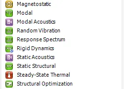
3.A table is displayed on the workbench,In it double click on the engineering data to edit for adding the materials such as Copper Alloy
(Non Linear), Aluminium Alloy (Non Linear) and Magnesium Alloy ( Non Linear) materials.
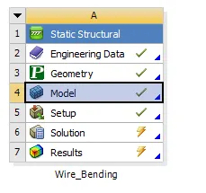
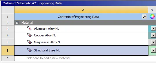
4.After assigning the data,close the engineering data and perform right click on the geomentry.
5.Import the given geomentry as given above and click on update on the model.
6. To check the given geomentry right click on it and it will open into the space claim to view the geomentry.
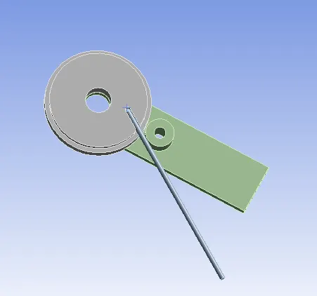
7.After checking the given geomentry close the space claim and open the model by double click on it or it can be opened by right click on the
model and select edit option to start the mechanical module to open.
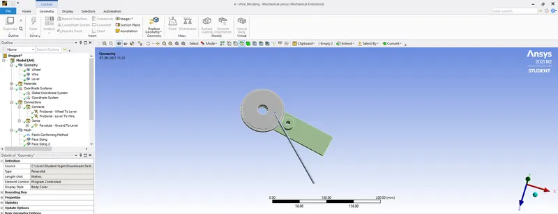
8.After opening the mechanical module,on the left side we can see a tree filter which contains all the components of the geomentry.
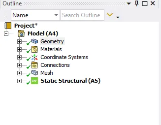
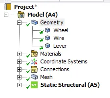
9.In the tree filter,Open the geomentry.In it we can find the three components and rename these components according to the geomentry given.
10.Inside the tree filter some contacts have been created by default.Delete those contacts and create the new contacts for the geomentry.The
created contacts is shown in below fig.
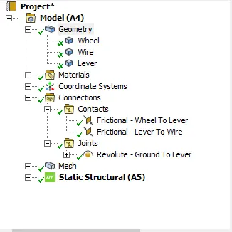
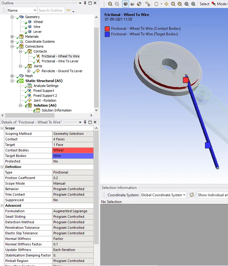
FIG:CONTACT B/W WHEEL TO WIRE
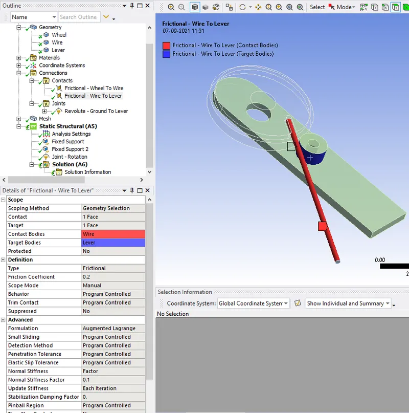
FIG:CONTACT B/W WIRE TO LEVER
11.Again in the contacts create a revoulte joint for lever as shown in fig below.
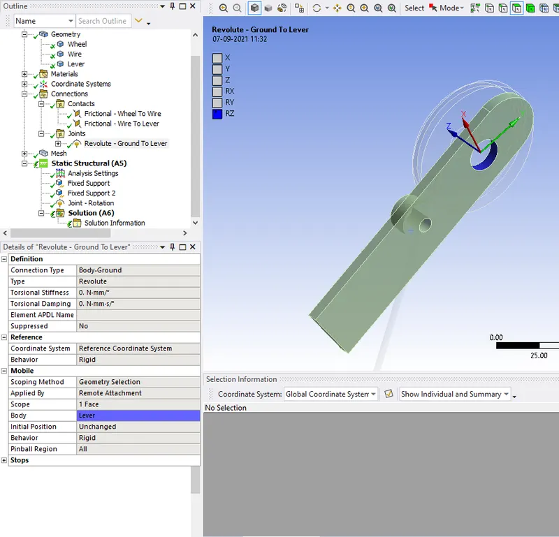
FIG:REVOLUTE GROUND TO LEVER
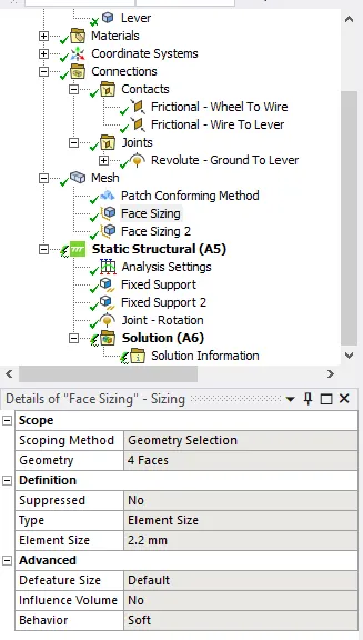
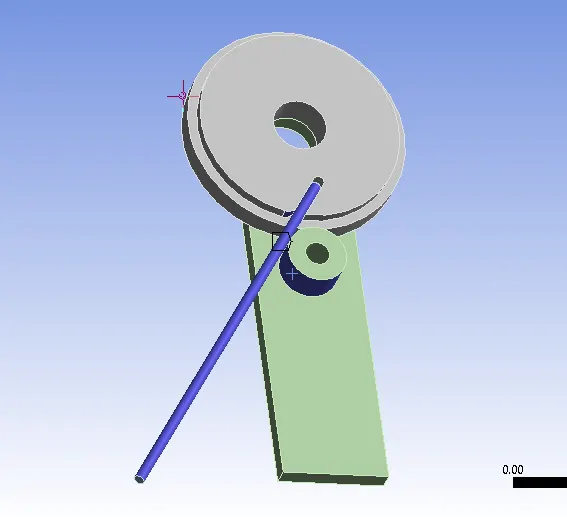
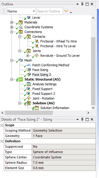
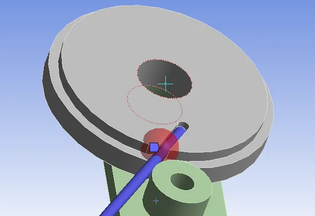
12.After that in the mesh create one method and two face sizing and assign the given components as shown in below.
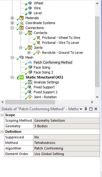
FIG:FOR 3 BODIES
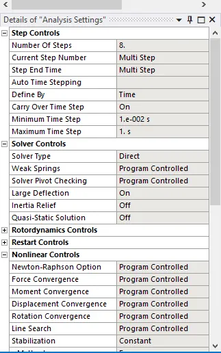
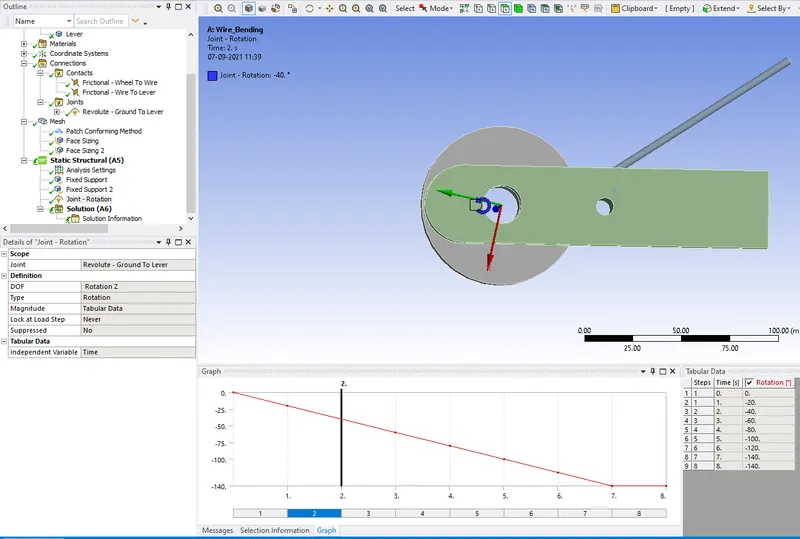
13.In analysis settings we have to run the analysis in 8 steps .
(A)For step 1 assign the given values as shown in below.
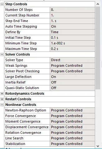
(B)For step 2 to 8 assign the given values as shown in below.
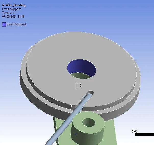
14.Create a fixed support for the wheel as shown in the below fig.
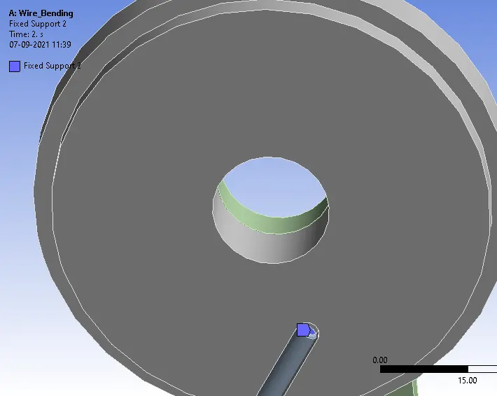
15.Again create a fixed support for the wire as shown in fig.
16.Create a revolute grounded joint to lever and by assigning the given values as shown.
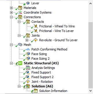
17.And now we are able to run the solution by right clicking on the solution button or by pressing the shortcut key F5.
RESULTS:
CASE 1 (COPPER ALLOY)
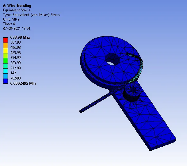
1.Equivalent stress of whole body.
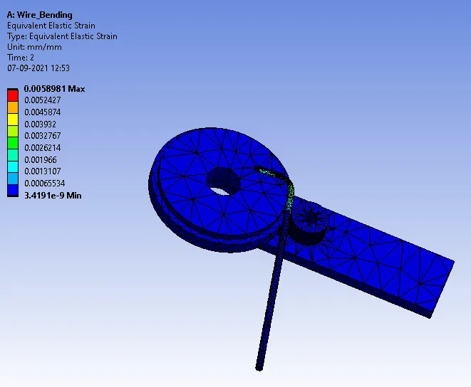
2.Equivalent strain of whole body.
3. Equivalent stress on the wire alone.
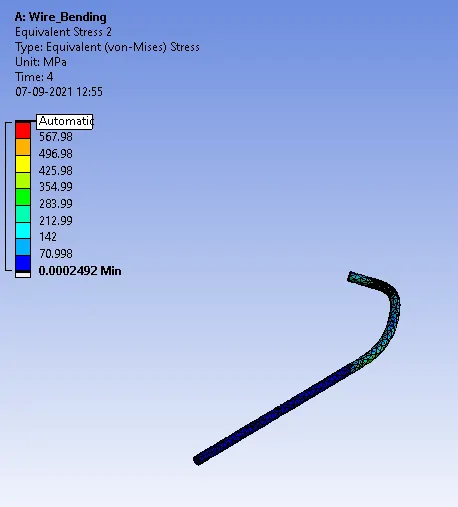
4.Equivalent strain on the wire alone.
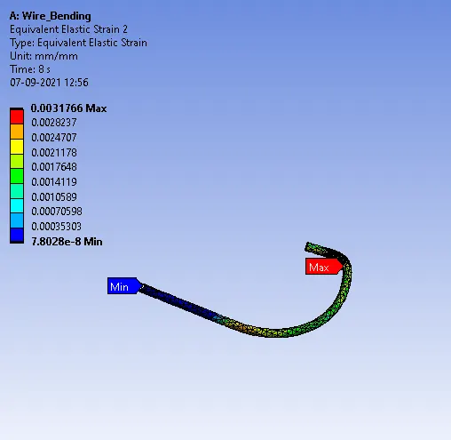
CASE 2 (ALUMINIUM ALLOY)
1.Equivalent stress of whole body.
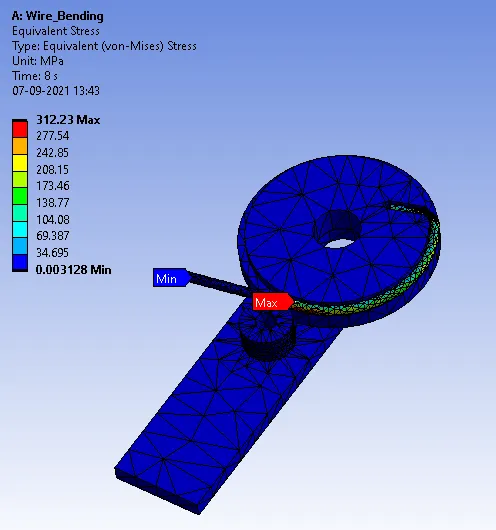
2.Equivalent strain of whole body.
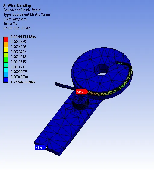
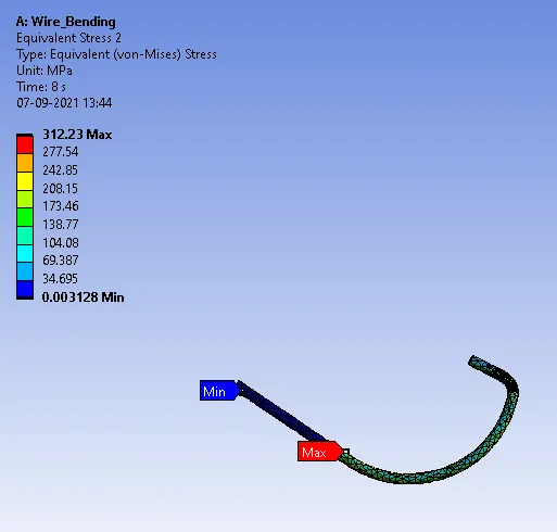
3. Equivalent stress on the wire alone.
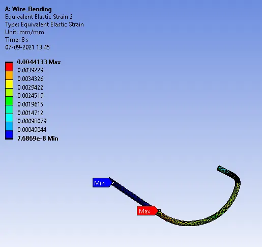
4.Equivalent strain on the wire alone.
CASE 3 (MAGNESIUM ALLOY)
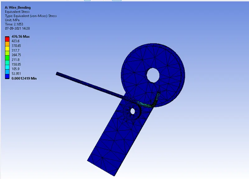
1.Equivalent stress of whole body.
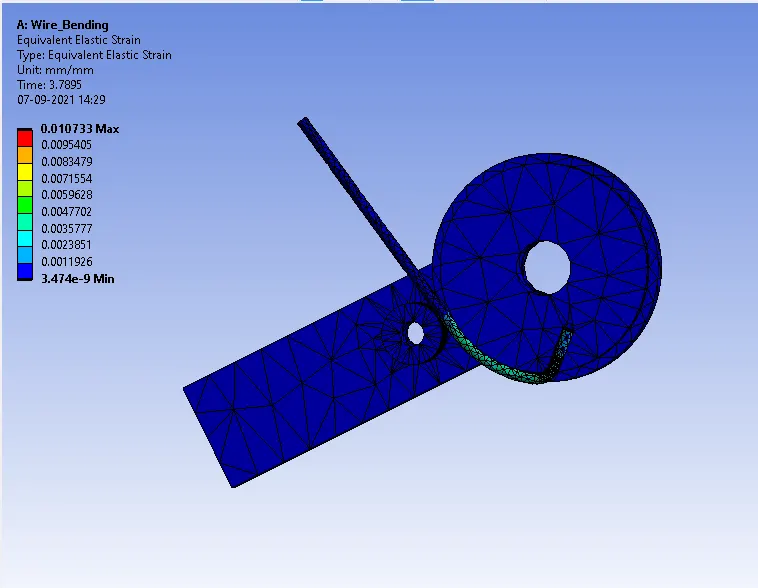
2.Equivalent strain of whole body.
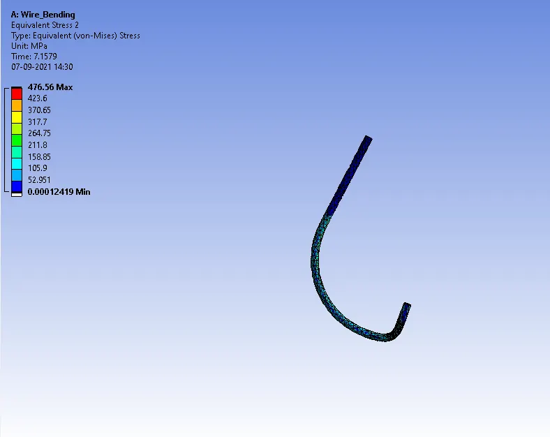
3. Equivalent stress on the wire alone.
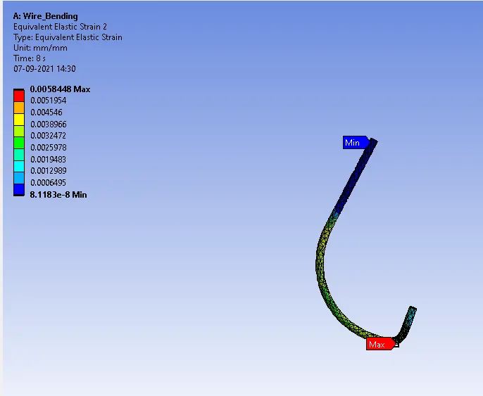
4.Equivalent strain on the wire alone.
COMPARISON OF EQUIVALENT STRESS ON THE WIRE ALONE:
| MATERIAL TYPE | COPPER ALLOY | ALUMINIUM ALLOY | MAGNESIUM ALLOY |
| STRESS ON THE WIRE |
MAX:638.98 MIN:0.0002492 |
MAX:312.23 MIN:0.003128 |
MAX:261.45 MIN:0.001931 |
COMPARISON OF EQUIVALENT STRAIN ON THE WIRE ALONE:
| MATERIAL TYPE | COPPER ALLOY | ALUMINIUM ALLOY | MAGNESIUM ALLOY |
| STRAIN ON THE WIRE |
MAX:0.0031766 MIN:7.8028e-8 |
MAX:0.0044133 MIN:7.6869E-8 |
MAX:0.0058448 MIN:8.1183e-8 |
CONCLUSION:
Thus,I performed an analysis to simulate the bending of a wire in ANSYS by using the materials as Copper Alloy (Non Linear),
Aluminium Alloy (Non Linear) and Magnesium Alloy ( Non Linear) for the wire alone.