Week - 3 Drop test Challenge
Introduction:
The term "drop test" refers to the free fall of a component. It is commonly used to test a product's ability to withstand rapidly applied
loads. Because the drop test is one of the functional test requirements for crash frame certification, the crash frame must pass the drop test
according to the guidelines before it can be sold for practical use.
The “Drop Test” also called as “Shock Test”, which is designed to measure the durability of equipment during loading/unloading and transportation.
Geomentry:
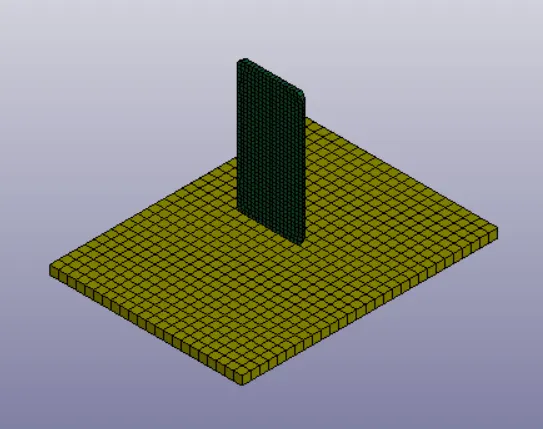
Isometric View
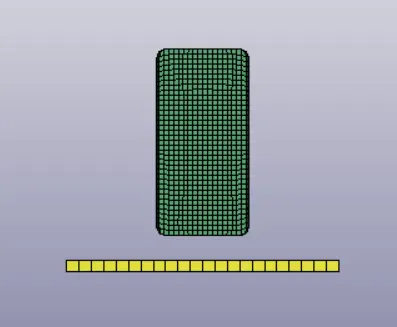
Front View
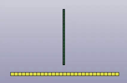
Side View
Material Specifications:
Cellphone:
Material Model: PIECEWISE_LINEAR_PLASTICITY (024)
Density: 0.0078500 gm / mm
Elastic Modulus: 200000 Mpa
Poisson’s Ratio: 0.25
Tensile Yield Strength: 350 Mpa
Rigid Wall:
Material Model: RIGID (020)
Density: 0.0024000gm / mm
Elastic Modulus: 41000 Mpa
Poisson’s Ratio: 0.2
Procedure:
1.Firstly open the LS-Dyna software.Now click on the File--Open--LS Dyna keyword File (ctrl+k) to open the geomentry given as shown in the
above figures.
2.The file contains both the shell and solid bodies as shown in the below fig.
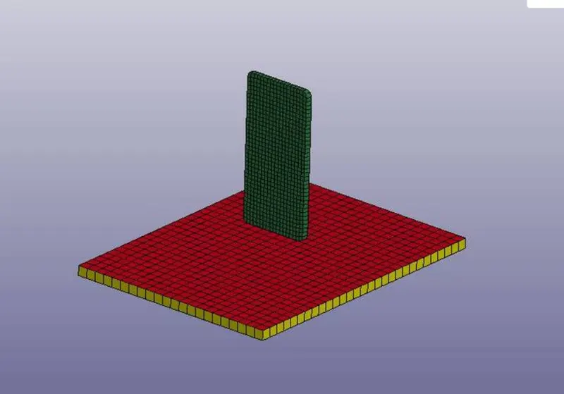
3.From the above the image we have to delete the red shell elements why because we fix the plate as rigid body so we dont need that red shell
elements.After deleting those elements it is shown as in below fig.
4.Now we have to create the different types of cards for running of the simulation.
Part:
5.Firstly create the material id's for both the wall and the phone as shown in the given below.
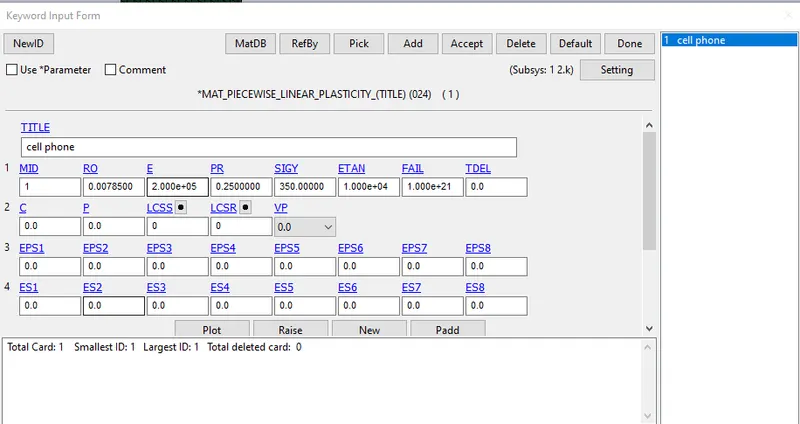
For Cell Phone
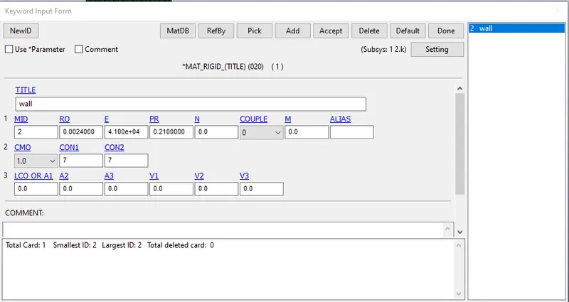
For Rigid Wall
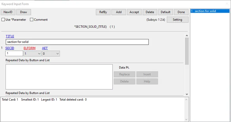
6.After creating the both materials for both the components,now create a Section Solid for both of the components as shown in the below fig.
7.Now assign the both material cards and sec-solid card to the given parts in the geomentry as shown in the below fig.
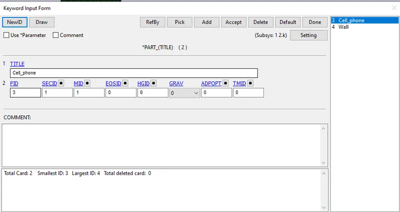
For Cell Phone
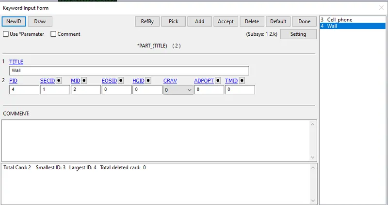
For Rigid Wall
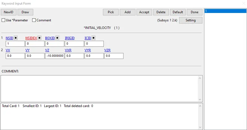
8.Now give the initial velocity for the cell phone as the value of -10.00 mm/ms in the negative z-direction as shown in the below fig.
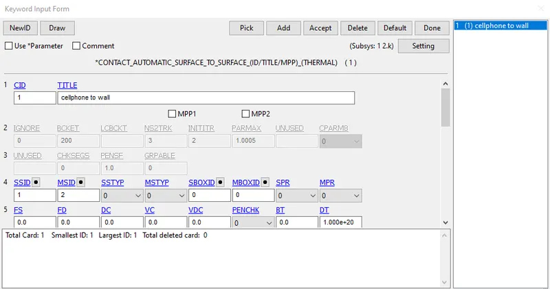
9.After that create a surface to surface contact between the cell phone and the wall as shown in the given below.
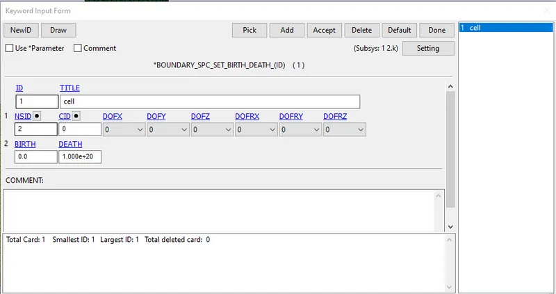
10.And also give the boundary conditions to the cell phone to define the constraints as shown in the fig.
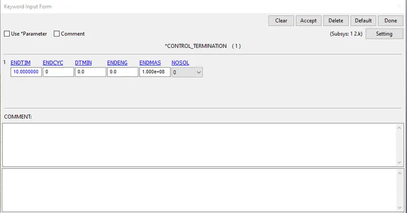
11.After creating all boundary conditions and contacts, create a card for termination and assign the end time value as 10ms as shown below.
12.Now after all conditions and termination details, we can generate output requests or results what we want from the analysis.
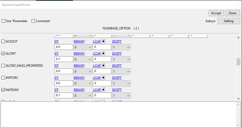
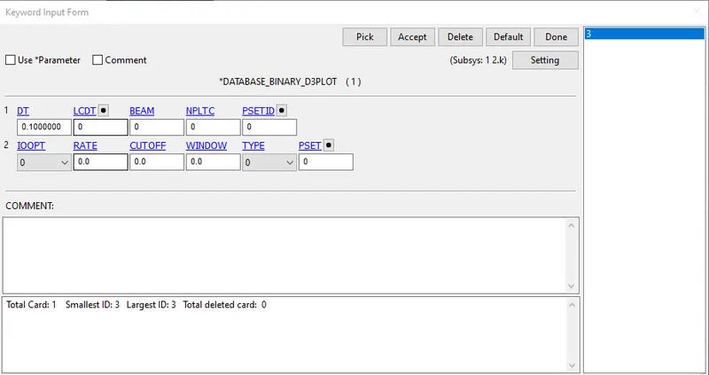
13.For that, we have to create cards for output. For animation and other part related data, create “BINARY_D3PLOT”, from database and “GLSTAT”,
“MATSUM”, from ASCII_option in database.
Calculations:
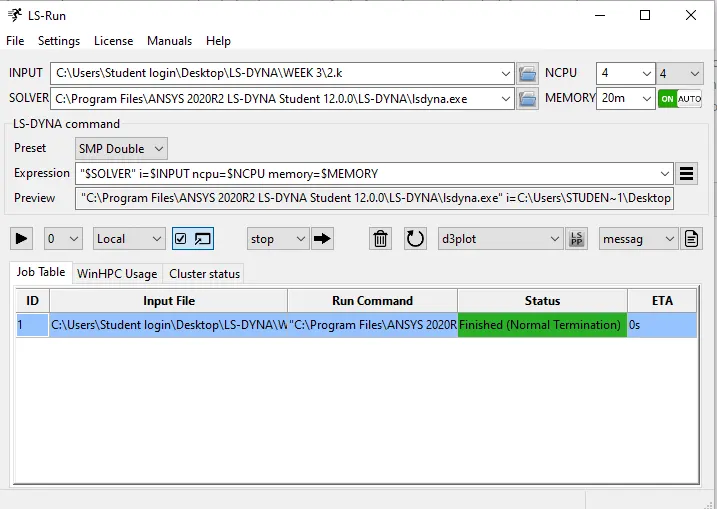
Now for calculation of all analysis, run the simulation as per availability of the core of CPU bu giving the value in “NCPU”.
Timing Info:
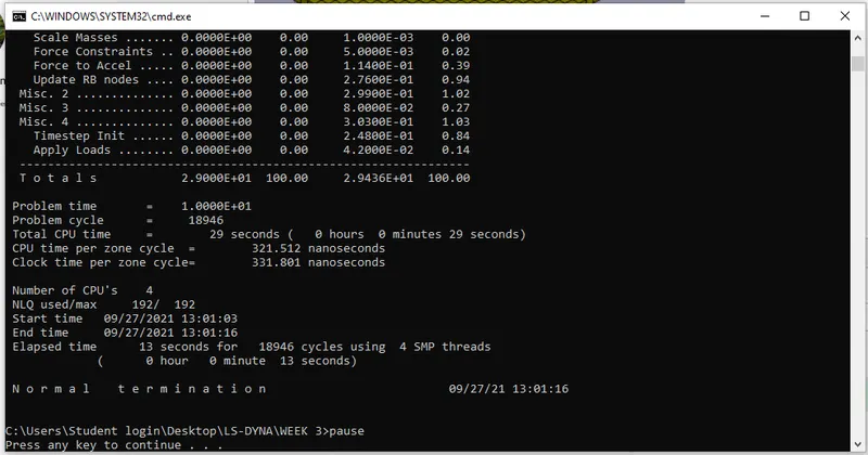
Make sure that Termination is Normal as shown in above image.
Results:
Open the Binary “d3plot” file in LS-PrePost and check the results.
Effective Von-mises Stress:
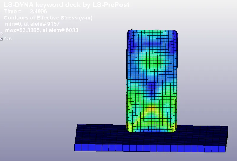
Here we can see that maximum stress generating is 63.3885 Mpa at 2.5 ms.
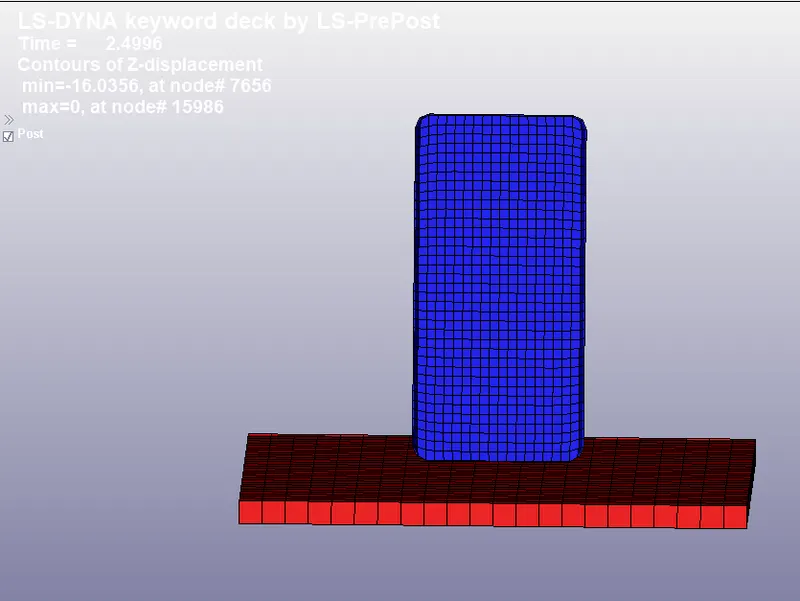
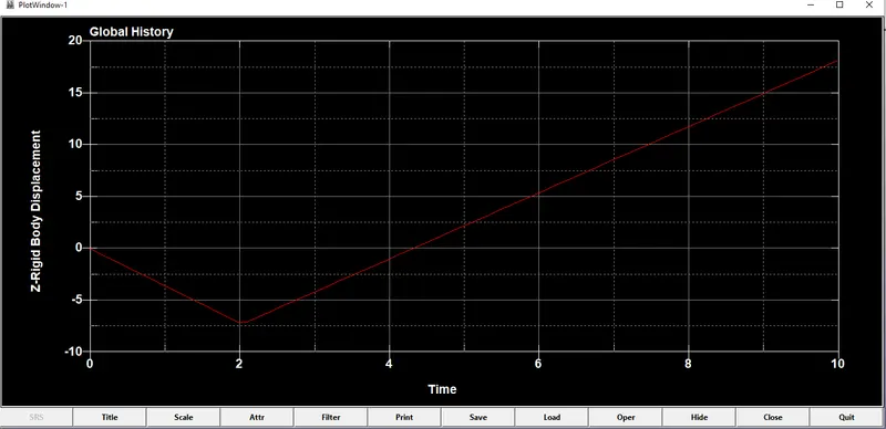
Displacement:
Global Energies:
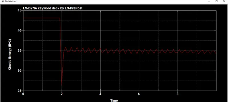
Kinetic Energy
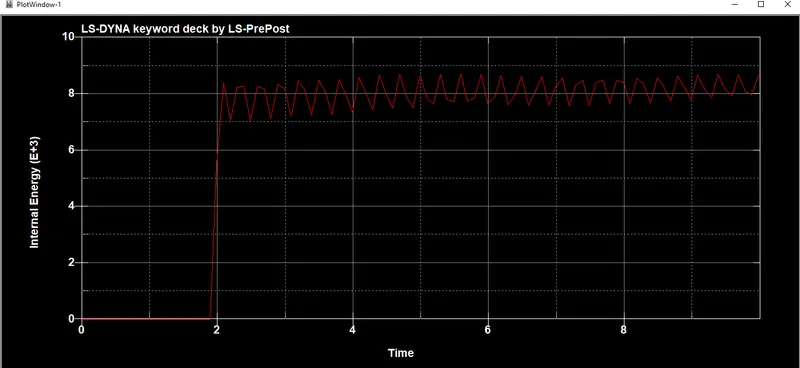
Internal Energy
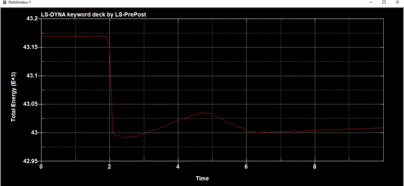
Total Energy
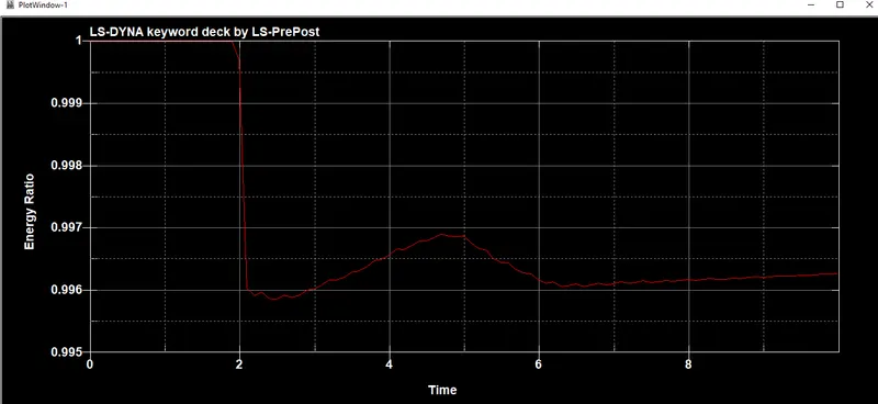
Energy Ratio
Conclusion:
This concludes Material modeling strategy considerably acceptable for this case; however different Material model should be checked with different
loading condition to arrive at correctness of modeling strategy of the simulation. The simulation results adds confidence to the Material modeling
approach and endorses the mesh size, element selection and contact definitions specific for problem describe in this analysis. This drop test
simulation helps to improve the design of Cellphone while it is in design life cycle. We can try different Material models and also check for the
various output results for more accurate results.