Week - 10 Hyperelastic Material Models
Aim:
To built a material model for the hyper-elasic material using the given data from experimental tensile test and compare the output results for
the simulation of a tensile test by using of a dog bone specimen model with the actual experimental results validating the model.
Procedure:
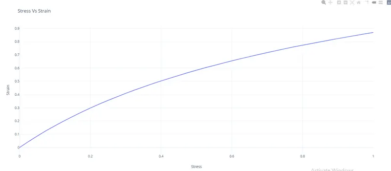
1.By using of the engineering stress and engineering strain data provided,a curve is formed and input this curve into the material model using
define->curve’ key-wards.
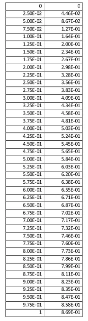
An excel sheet is maintained with this input curve as well as the simulation results for comparison.
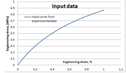
2.For the dog bone model,a tensile test setup is given where the boundary conditions are:
a)One end is going to be fixed in with all DOFs locked except the translational in lateral direction to allow the compression.
b)All nodes on the other side of the end are added to a node set to which a prescribed boundary condtion of displacement is to be applied
along the longitudinal axis.
c)On the either sides of the end the middle node is to be constrained in all other DOF except translational in the longitudinal axis to avoid
contacting with boundary conditions and keep the loading tensile in nature.
3.A linear displacement curve is to be defined to get the experimental test strain which as stated is 100% .The specimen is strecthed to twice its
original length.
4. The simulation is performed first only to get the hyper-elastic constants for N=1 through N=3. The fitted curve is tested against the input curve
as well. Then these constants are used to define the curve emulating the 3 stages and the results are noted.
5. Finally for the actual simulation for validating the model using the 2 material models mentioned before, the setup is kept the same and the
necessary outputs were requested in ‘database’ keyword and the results were compared to the input curves.
6. To understand the process better, implicit analysis is performed.
1.Analysis model and setup:
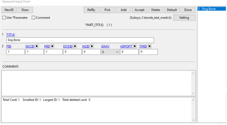
1.Import the meshed model of dog bone specimen.
2.Keyword--> Part
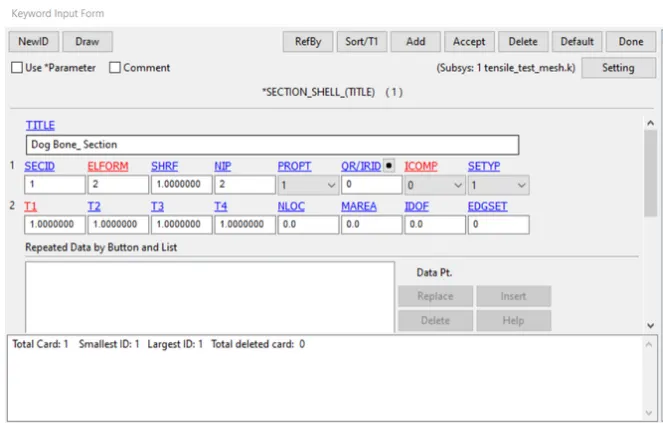
3.Create-->Section_shell and assign the thickness as shown.
4.Define-->Load curve with the given data as follows:
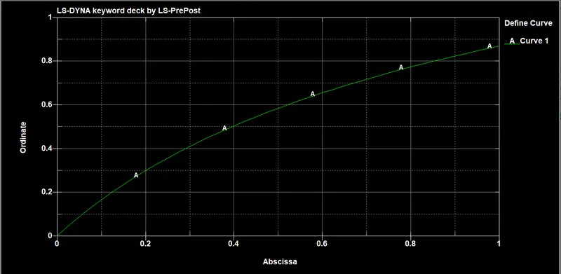
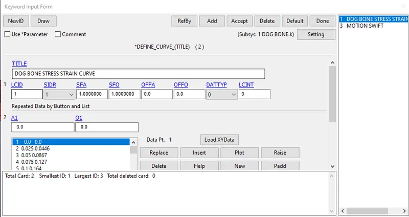
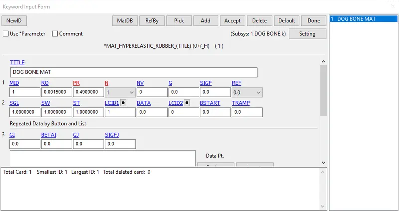
5.Input the material card as follows:
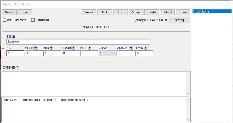
6.Now assign the both material card and the section shell card to the given dogbone part as shown.
7.From the given model we have to perform the tensile experiment in which the dog bone should be get deform only in the y-direction when it is
pulled in x-direction.
8.For that SPC_SET has to be created to fix along all sides except in the y-direction.
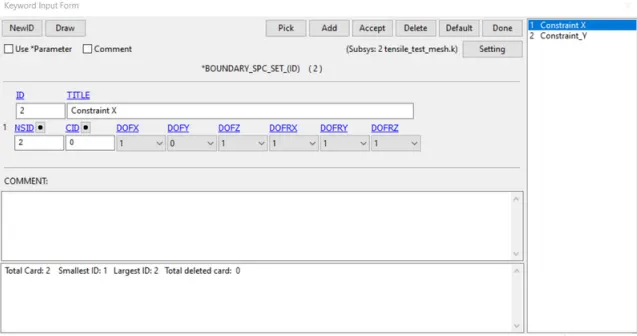
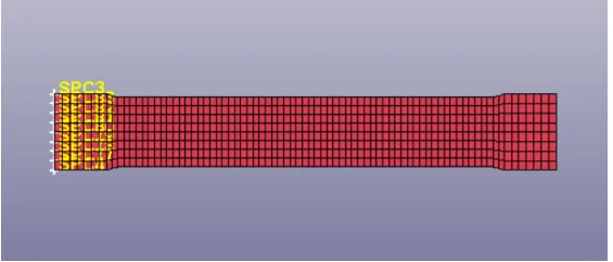
Constraints along in x-direction
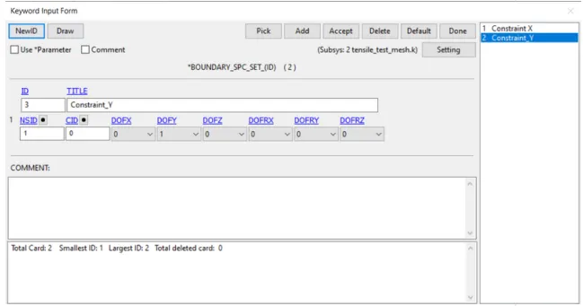
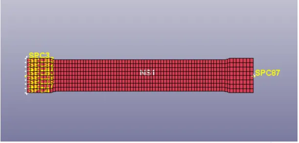
Constraints along in y-direction
9.To specify the motion for the specimen, create a prescribed motion set as follows.
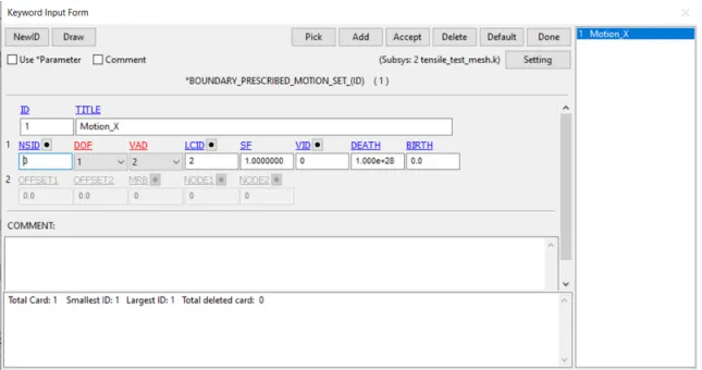
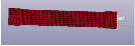
- PSM is created using LCID. The strech ratio is about 100%
λ = 2,
ε = λ - 1
ε = 2 - 1=1
ε = ΔL/L=1
L = 145
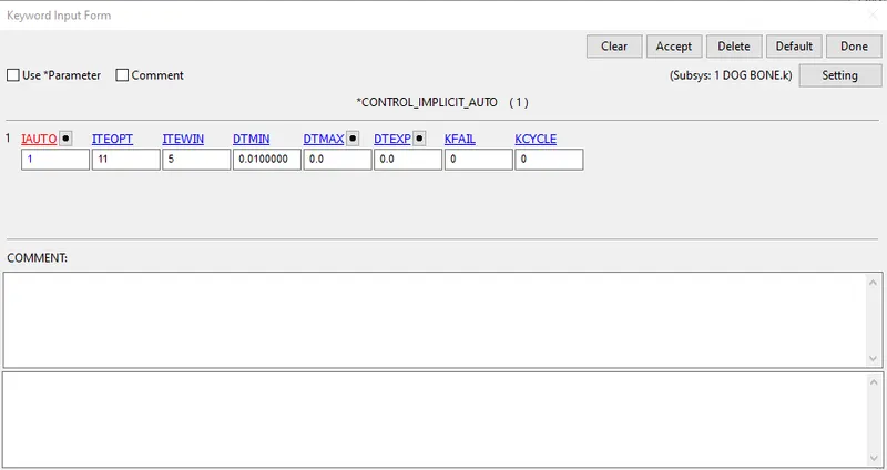
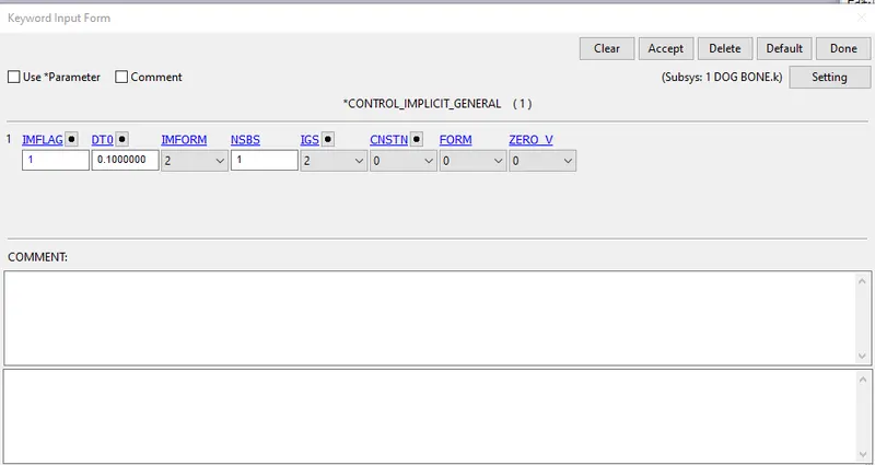
10.Create some control cards as follows.
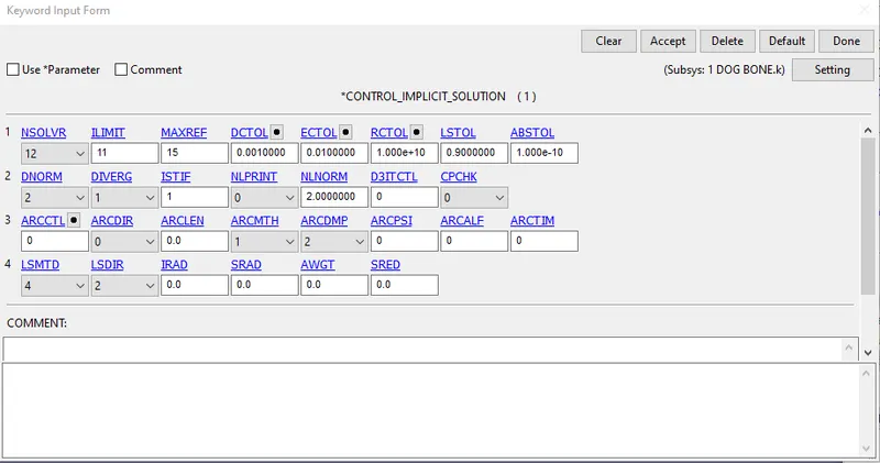
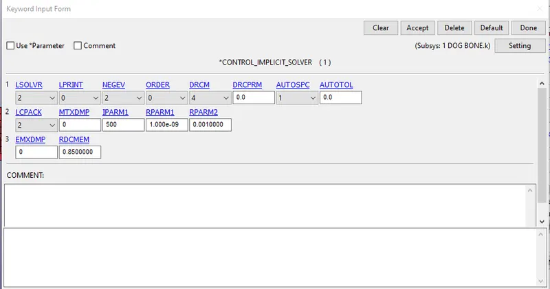
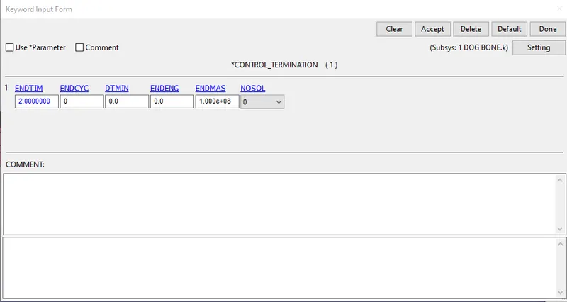
11.ASCII_Option Keyword Requests :
SECFORC - Cross Sectional Forces
GLSTAT - Global Data
Material Energy
ELOUT - Element Output Data
NODOUT - Nodal Displacemment, Velocity, Acceleration Data
SLEOUT - Sliding Interface Energies.
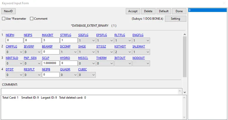
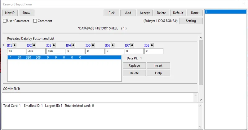
12.Create some required database keycards as shown.
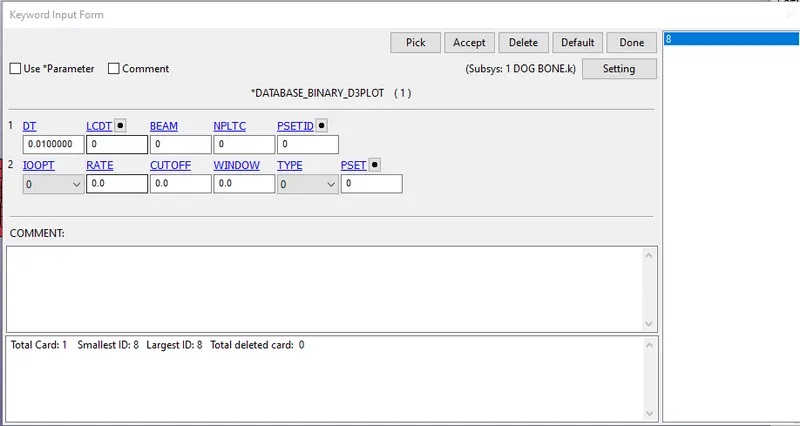
The material constats are extracted by running the model,
N:=Number of constants to solve for:
EQ.1: Solve for C10 and C01,
EQ.2: Solve for C10, C01, C11, C20, and C02,
EQ.3: Solve for C10, C01, C11, C20, C02, and C30
The Mooney-Rivlin constants for each case are stored in the d3hsp file.
Case 1:N=1
Mooney constant c1 = 0.1768E+00
Mooney constant c2 = 0.1474E+00
Change the Number of constant value to 0. Input the constant values in C10 and C01.
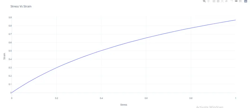
We receive true stress & true strain from LS DYNA, in which it is converted into engineering stress and engineering strain.
We receive true stress & true strain from LS DYNA, in which it is converted into engineering stress and engineering strain.
Strech Ratio Stress (σₜ) Strain (εₑ) = λ-1 σₑ=(σₜ/(1+εₑ) Eng.Strain Eng.Stress
1.00E+00 0.00E+00 0 0 0 0
1.03E+00 4.81E-02 0.025 0.046926829 2.50E-02 4.46E-02
1.05E+00 9.52E-02 0.05 0.090695238 5.00E-02 8.67E-02
1.08E+00 1.42E-01 0.075 0.131627907 7.50E-02 1.27E-01
1.10E+00 1.87E-01 0.1 0.17 1.00E-01 1.64E-01
1.13E+00 2.32E-01 0.125 0.206133333 1.25E-01 2.00E-01
1.15E+00 2.76E-01 0.15 0.24026087 1.50E-01 2.34E-01
1.18E+00 3.20E-01 0.175 0.272425532 1.75E-01 2.67E-01
1.20E+00 3.64E-01 0.2 0.303 2.00E-01 2.98E-01
1.23E+00 4.07E-01 0.225 0.331918367 2.25E-01 3.28E-01
1.25E+00 4.49E-01 0.25 0.35952 2.50E-01 3.56E-01
1.28E+00 4.92E-01 0.275 0.385882353 2.75E-01 3.83E-01
1.30E+00 5.34E-01 0.3 0.411076923 3.00E-01 4.09E-01
1.33E+00 5.77E-01 0.325 0.435169811 3.25E-01 4.34E-01
1.35E+00 6.19E-01 0.35 0.458296296 3.50E-01 4.58E-01
1.38E+00 6.61E-01 0.375 0.480581818 3.75E-01 4.81E-01
1.40E+00 7.03E-01 0.4 0.502 4.00E-01 5.03E-01
1.43E+00 7.45E-01 0.425 0.522666667 4.25E-01 5.24E-01
1.45E+00 7.87E-01 0.45 0.54262069 4.50E-01 5.45E-01
1.48E+00 8.29E-01 0.475 0.561966102 4.75E-01 5.65E-01
1.50E+00 8.71E-01 0.5 0.580666667 5.00E-01 5.84E-01
1.53E+00 9.13E-01 0.525 0.598885246 5.25E-01 6.03E-01
1.55E+00 9.56E-01 0.55 0.616516129 5.50E-01 6.20E-01
1.58E+00 9.98E-01 0.575 0.633714286 5.75E-01 6.38E-01
1.60E+00 1.04E+00 0.6 0.650625 6.00E-01 6.55E-01
1.63E+00 1.08E+00 0.625 0.667076923 6.25E-01 6.71E-01
1.65E+00 1.13E+00 0.65 0.682424242 6.50E-01 6.87E-01
1.68E+00 1.17E+00 0.675 0.698507463 6.75E-01 7.02E-01
1.70E+00 1.21E+00 0.7 0.713529412 7.00E-01 7.17E-01
1.73E+00 1.26E+00 0.725 0.728695652 7.25E-01 7.32E-01
1.75E+00 1.30E+00 0.75 0.742857143 7.50E-01 7.46E-01
1.78E+00 1.35E+00 0.775 0.757746479 7.75E-01 7.60E-01
1.80E+00 1.39E+00 0.8 0.77166666 7 8.00E-01 7.73E-01
1.83E+00 1.43E+00 0.825 0.785205479 8.25E-01 7.86E-01
1.85E+00 1.48E+00 0.85 0.798918919 8.50E-01 7.99E-01
1.88E+00 1.52E+00 0.875 0.812266667 8.75E-01 8.11E-01
1.90E+00 1.57E+00 0.9 0.825789474 9.00E-01 8.23E-01
1.93E+00 1.61E+00 0.925 0.838441558 9.25E-01 8.35E-01
1.95E+00 1.66E+00 0.95 0.851282051 9.50E-01 8.47E-01
1.98E+00 1.71E+00 0.975 0.864303797 9.75E-01 8.58E-01
2.00E+00 1.75E+00 1 0.8765 1 8.69E-01
Engineering Strain = Stretch -1
Engineering Stress = True Stress/Stretch
Case II: N = 2 (Second order polynomial)
Hyperelastic Constant C10= 0.2595E+00
Hyperelastic Constant C01= 0.4594E-01
Hyperelastic Constant C11= -0.2092E-01
Hyperelastic Constant C20= 0.2914E-02
Hyperelastic Constant C02= 0.1016E-02
Hyperelastic Constant C30= 0.0000E+00
Change the Number of constant value to 0. Input the constant values in C10 and C01.
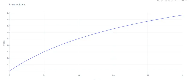
We receive true stress & true strain from LS DYNA, in which it is converted into engineering stress and engineering strain.
| Strech Ratio | Stress (σₜ) | Strain (εₑ) = λ-1 | σₑ=(σₜ/(1+εₑ) | Eng.Strain | Eng.Stress |
| 1.00E+00 | 0.00E+00 | 0 | 0 | 0 | 0 |
| 1.03E+00 | 4.56E-02 | 0.025 | 0.044526829 | 2.50E-02 | 4.46E-02 |
| 1.05E+00 | 9.10E-02 | 0.05 | 0.086638095 | 5.00E-02 | 8.67E-02 |
| 1.08E+00 | 1.36E-01 | 0.075 | 0.126511628 | 7.50E-02 | 1.27E-01 |
| 1.10E+00 | 1.81E-01 | 0.1 | 0.164363636 | 1.00E-01 | 1.64E-01 |
| 1.13E+00 | 2.25E-01 | 0.125 | 0.200266667 | 1.25E-01 | 2.00E-01 |
| 1.15E+00 | 2.70E-01 | 0.15 | 0.234434783 | 1.50E-01 | 2.34E-01 |
| 1.18E+00 | 3.14E-01 | 0.175 | 0.266893617 | 1.75E-01 | 2.67E-01 |
| 1.20E+00 | 3.58E-01 | 0.2 | 0.298 | 2.00E-01 | 2.98E-01 |
| 1.23E+00 | 4.01E-01 | 0.225 | 0.327591837 | 2.25E-01 | 3.28E-01 |
| 1.25E+00 | 4.45E-01 | 0.25 | 0.35592 | 2.50E-01 | 3.56E-01 |
| 1.28E+00 | 4.88E-01 | 0.275 | 0.383058824 | 2.75E-01 | 3.83E-01 |
| 1.30E+00 | 5.32E-01 | 0.3 | 0.409 | 3.00E-01 | 4.09E-01 |
| 1.33E+00 | 5.75E-01 | 0.325 | 0.433962264 | 3.25E-01 | 4.34E-01 |
| 1.35E+00 | 6.18E-01 | 0.35 | 0.457925926 | 3.50E-01 | 4.58E-01 |
| 1.38E+00 | 6.61E-01 | 0.375 | 0.480945455 | 3.75E-01 | 4.81E-01 |
| 1.40E+00 | 7.04E-01 | 0.4 | 0.503071429 | 4.00E-01 | 5.03E-01 |
| 1.43E+00 | 7.47E-01 | 0.425 | 0.524421053 | 4.25E-01 | 5.24E-01 |
| 1.45E+00 | 7.90E-01 | 0.45 | 0.545034483 | 4.50E-01 | 5.45E-01 |
| 1.48E+00 | 8.33E-01 | 0.475 | 0.564881356 | 4.75E-01 | 5.65E-01 |
| 1.50E+00 | 8.76E-01 | 0.5 | 0.584066667 | 5.00E-01 | 5.84E-01 |
| 1.53E+00 | 9.19E-01 | 0.525 | 0.602622951 | 5.25E-01 | 6.03E-01 |
| 1.55E+00 | 9.62E-01 | 0.55 | 0.620516129 | 5.50E-01 | 6.20E-01 |
| 1.58E+00 | 1.01E+00 | 0.575 | 0.638095238 | 5.75E-01 | 6.38E-01 |
| 1.60E+00 | 1.05E+00 | 0.6 | 0.655 | 6.00E-01 | 6.55E-01 |
| 1.63E+00 | 1.09E+00 | 0.625 | 0.670769231 | 6.25E-01 | 6.71E-01 |
| 1.65E+00 | 1.13E+00 | 0.65 | 0.686666667 | 6.50E-01 | 6.87E-01 |
| 1.68E+00 | 1.18E+00 | 0.675 | 0.702089552 | 6.75E-01 | 7.02E-01 |
| 1.70E+00 | 1.22E+00 | 0.7 | 0.717058824 | 7.00E-01 | 7.17E-01 |
| 1.73E+00 | 1.26E+00 | 0.725 | 0.731594203 | 7.25E-01 | 7.32E-01 |
| 1.75E+00 | 1.31E+00 | 0.75 | 0.745714286 | 7.50E-01 | 7.46E-01 |
| 1.78E+00 | 1.35E+00 | 0.775 | 0.75943662 | 7.75E-01 | 7.60E-01 |
| 1.80E+00 | 1.39E+00 | 0.8 | 0.772777778 | 8.00E-01 | 7.73E-01 |
| 1.83E+00 | 1.44E+00 | 0.825 | 0.78630137 | 8.25E-01 | 7.86E-01 |
| 1.85E+00 | 1.48E+00 | 0.85 | 0.798918919 | 8.50E-01 | 7.99E-01 |
| 1.88E+00 | 1.52E+00 | 0.875 | 0.8112 | 8.75E-01 | 8.11E-01 |
| 1.90E+00 | 1.56E+00 | 0.9 | 0.823157895 | 9.00E-01 | 8.23E-01 |
| 1.93E+00 | 1.61E+00 | 0.925 | 0.835324675 | 9.25E-01 | 8.35E-01 |
| 1.95E+00 | 1.65E+00 | 0.95 | 0.846666667 | 9.50E-01 | 8.47E-01 |
| 1.98E+00 | 1.70E+00 | 0.975 | 0.858227848 | 9.75E-01 | 8.58E-01 |
| 2.00E+00 | 1.74E+00 | 1 | 0.869 | 1 | 8.69E-01 |
Case 3: N = 3
Hyperelastic Constant C10= 0.2611E+00
Hyperelastic Constant C01= 0.4420E-01
Hyperelastic Constant C11= -0.6074E-02
Hyperelastic Constant C20= -0.2667E-02
Hyperelastic Constant C02= -0.9968E-02
Hyperelastic Constant C30= 0.1565E-03
Change the Number of constant value to 0. Input the constant values in C10, C01, C11, C20, C02, and C30
We receive true stress & true strain from LS DYNA, in which it is converted into engineering stress and engineering strain.
| Strech Ratio | Stress (σₜ) | Strain (εₑ) = λ-1 | σₑ=(σₜ/(1+εₑ) | Eng.Strain | Eng.Stress |
| 1.00E+00 | 0.00E+00 | 0 | 0 | 0 | 0 |
| 1.03E+00 | 4.56E-02 | 0.025 | 0.044517073 | 2.50E-02 | 4.46E-02 |
| 1.05E+00 | 9.10E-02 | 0.05 | 0.086628571 | 5.00E-02 | 8.67E-02 |
| 1.08E+00 | 1.36E-01 | 0.075 | 0.126511628 | 7.50E-02 | 1.27E-01 |
| 1.10E+00 | 1.81E-01 | 0.1 | 0.164363636 | 1.00E-01 | 1.64E-01 |
| 1.13E+00 | 2.25E-01 | 0.125 | 0.200266667 | 1.25E-01 | 2.00E-01 |
| 1.15E+00 | 2.70E-01 | 0.15 | 0.234434783 | 1.50E-01 | 2.34E-01 |
| 1.18E+00 | 3.14E-01 | 0.175 | 0.266978723 | 1.75E-01 | 2.67E-01 |
| 1.20E+00 | 3.58E-01 | 0.2 | 0.298 | 2.00E-01 | 2.98E-01 |
| 1.23E+00 | 4.01E-01 | 0.225 | 0.327591837 | 2.25E-01 | 3.28E-01 |
| 1.25E+00 | 4.45E-01 | 0.25 | 0.35592 | 2.50E-01 | 3.56E-01 |
| 1.28E+00 | 4.88E-01 | 0.275 | 0.383058824 | 2.75E-01 | 3.83E-01 |
| 1.30E+00 | 5.32E-01 | 0.3 | 0.409 | 3.00E-01 | 4.09E-01 |
| 1.33E+00 | 5.75E-01 | 0.325 | 0.433962264 | 3.25E-01 | 4.34E-01 |
| 1.35E+00 | 6.18E-01 | 0.35 | 0.457925926 | 3.50E-01 | 4.58E-01 |
| 1.38E+00 | 6.61E-01 | 0.375 | 0.480945455 | 3.75E-01 | 4.81E-01 |
| 1.40E+00 | 7.04E-01 | 0.4 | 0.503071429 | 4.00E-01 | 5.03E-01 |
| 1.43E+00 | 7.47E-01 | 0.425 | 0.524421053 | 4.25E-01 | 5.24E-01 |
| 1.45E+00 | 7.90E-01 | 0.45 | 0.544965517 | 4.50E-01 | 5.45E-01 |
| 1.48E+00 | 8.33E-01 | 0.475 | 0.564881356 | 4.75E-01 | 5.65E-01 |
| 1.50E+00 | 8.76E-01 | 0.5 | 0.584066667 | 5.00E-01 | 5.84E-01 |
| 1.53E+00 | 9.19E-01 | 0.525 | 0.602622951 | 5.25E-01 | 6.03E-01 |
| 1.55E+00 | 9.62E-01 | 0.55 | 0.620516129 | 5.50E-01 | 6.20E-01 |
| 1.58E+00 | 1.01E+00 | 0.575 | 0.638095238 | 5.75E-01 | 6.38E-01 |
| 1.60E+00 | 1.05E+00 | 0.6 | 0.655 | 6.00E-01 | 6.55E-01 |
| 1.63E+00 | 1.09E+00 | 0.625 | 0.671384615 | 6.25E-01 | 6.71E-01 |
| 1.65E+00 | 1.13E+00 | 0.65 | 0.686666667 | 6.50E-01 | 6.87E-01 |
| 1.68E+00 | 1.18E+00 | 0.675 | 0.702089552 | 6.75E-01 | 7.02E-01 |
| 1.70E+00 | 1.22E+00 | 0.7 | 0.717058824 | 7.00E-01 | 7.17E-01 |
| 1.73E+00 | 1.26E+00 | 0.725 | 0.731594203 | 7.25E-01 | 7.32E-01 |
| 1.75E+00 | 1.31E+00 | 0.75 | 0.745714286 | 7.50E-01 | 7.46E-01 |
| 1.78E+00 | 1.35E+00 | 0.775 | 0.75943662 | 7.75E-01 | 7.60E-01 |
| 1.80E+00 | 1.39E+00 | 0.8 | 0.772777778 | 8.00E-01 | 7.73E-01 |
| 1.83E+00 | 1.44E+00 | 0.825 | 0.78630137 | 8.25E-01 | 7.86E-01 |
| 1.85E+00 | 1.48E+00 | 0.85 | 0.798918919 | 8.50E-01 | 7.99E-01 |
| 1.88E+00 | 1.52E+00 | 0.875 | 0.8112 | 8.75E-01 | 8.11E-01 |
| 1.90E+00 | 1.56E+00 | 0.9 | 0.823157895 | 9.00E-01 | 8.23E-01 |
| 1.93E+00 | 1.61E+00 | 0.925 | 0.835324675 | 9.25E-01 | 8.35E-01 |
| 1.95E+00 | 1.65E+00 | 0.95 | 0.846666667 | 9.50E-01 | 8.47E-01 |
| 1.98E+00 | 1.70E+00 | 0.975 | 0.858227848 | 9.75E-01 | 8.58E-01 |
| 2.00E+00 | 1.74E+00 | 1 | 0.869 | 1 | 8.69E-01 |
Odgen Hyper Elastic Material Model:
The comparison is made in between the number of constants (N=1,3 and 5) in the odgen hyper elastic model.
Mat Card:
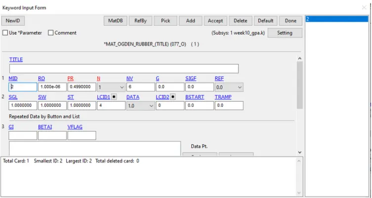
After changing the material card do the same procedure as mentioned above.
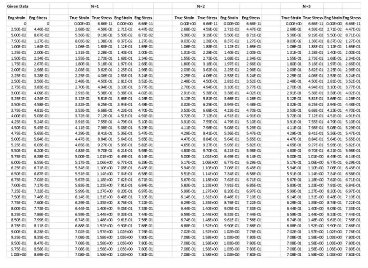
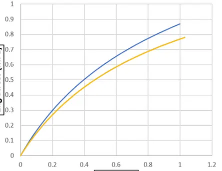
The values calculated after the running of the simulation is shown in the below fig.
Conclusion :
- By Comparing1st, 2nd & 3rd Order of polynomial. The best fit is of 1st degree of polynomial.
- The Mooney Rivlin is compared using stress-strain data from a Dogbone specimen tensile test with 100 percent strain rate and the results are verified.
- However, the engineering stress-strain curves obtained from the post-processing of the performed simulation indicate a slight variation in the values of engineering stresses and strains in comparison with the given experimental data. Similarly, the engineering stress-strain data obtained from uniaxial tensile test simulation of a dog bone specimen with MAT 077 Ogden rubber card indicates a slight variation in the values of engineering stresses and strains in comparison with the given experimental data. This could have happened either due to improper modeling of material card parameters such as density & poisons ratio or due to the high non-linearity of the material itself.