Bird Strike - Project - 2
Aim:
To simulate a bird strike which is a non-linear transient dynamic problem with a jet engine blade and we have to evaluate all the reults after the
simulation.
1.The given file contains all the parts of the bird strike.We have to seperate them and save in a sub folder.
2.The suitable and required materials have to created and saved in a sub folder.
3.The node number, element number and part numbers are assigned as required.
4.We have create a main file that should have only the .k file and run the simulation(explicit).
5.Study the mass scaling by changing the value of dt2ms.
Procedure:
1.The given project will consists of four components namely engine casing,hub blades and bird etc.So,these parts are seperated by the single
components and save them in a sub folder.
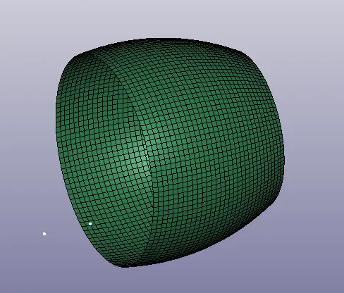
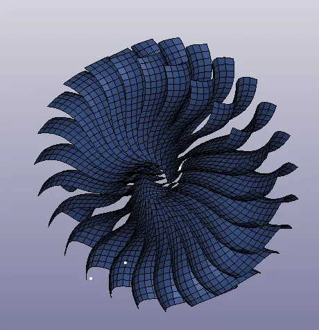
Fig: Engine casing Fig : Blades
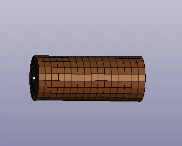
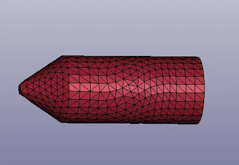
Fig:Bird Fig:Hub

Fig: The different components are saved in different key files.
2.The individually saved files are now opened in the LS-Dyna to check the elements,nodes and other keywords.These can be checked by going to
the Toolbar-->FEM-->Model and part--> Renumbering.
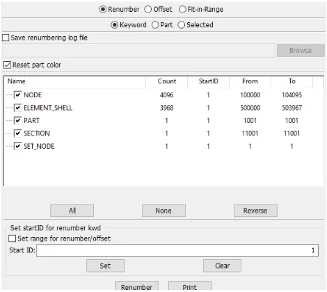
Fig:Renumber
3.Assign the section cards and material cards for the seperated components as shown in the below figures.
a.Engine hub
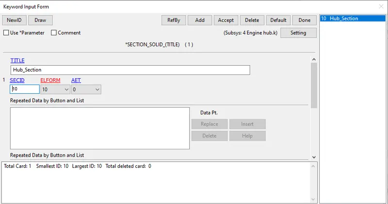
Fig:Solid section
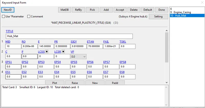
Fig:Hub_Mat
b.Engine blade
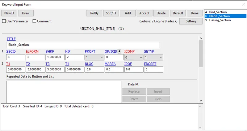
Fig:Section_shell
Here we will assign the material(MAT_024), but here we will include the material file given question assign that material to the part card.
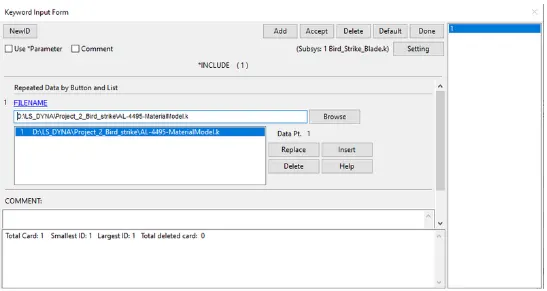
Fig: Include keyword used to input the material model for blade
As we can see that E= 68.94 Gpa and FAIL = 0.2723 which means the material will fail when it reaches 27.23 % of the plastic strain value. the
thickness assign to the shell section is 3mm for the blade.
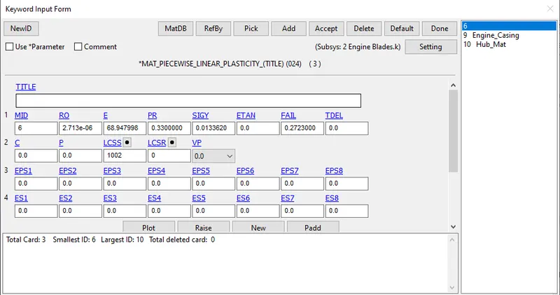
Fig: Elasto-plastic material card defined
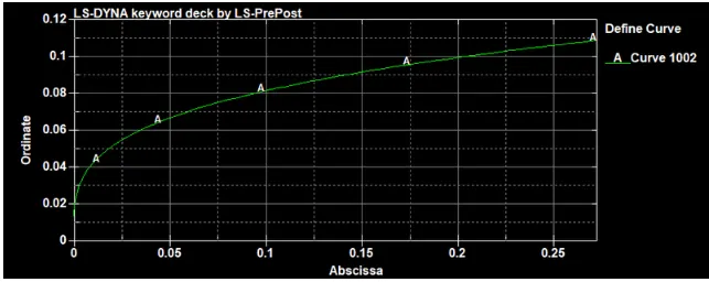
Load curve defined
Below is the data of the material that we have input to the blade material card through LSID (12000)
c.Engine casing
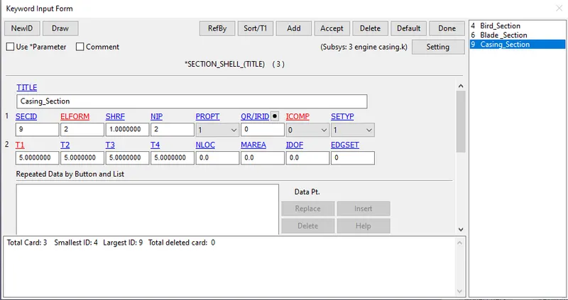
Fig:Section_shell
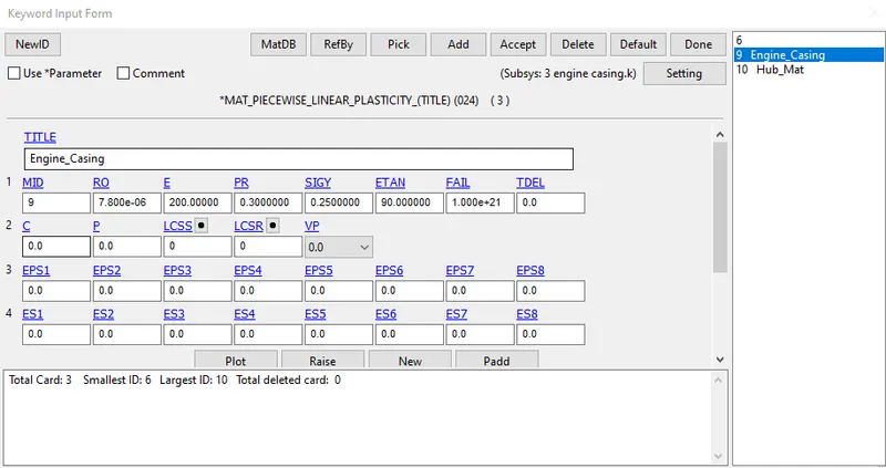
Fig:Engine casing mat
d.Engine bird
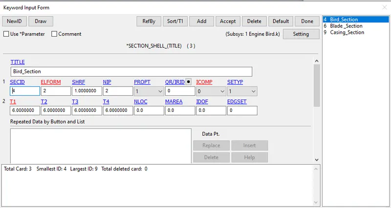
Fig:Section_shell
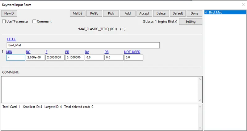
Fig: Elastic mat card for bird
4.Now assign the both mat cards and section cards to their respective parts as shown in below figures.
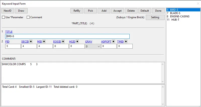
Fig: For Bird
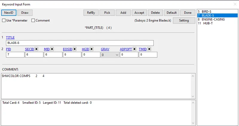
Fig: For Blade
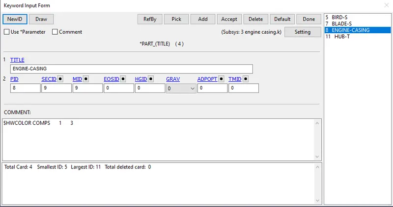
Fig: For Engine Casing
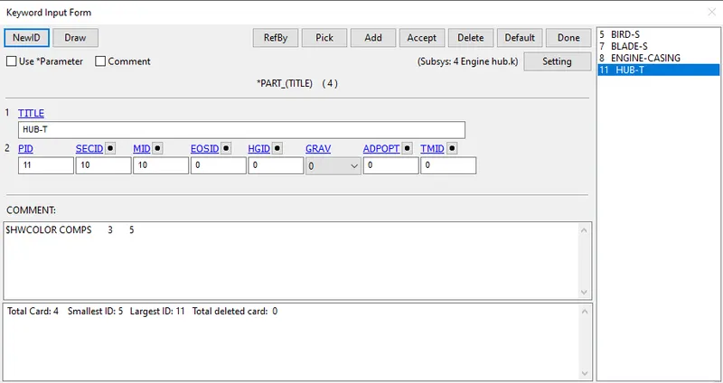
Fig: For Hub
5.Now apply the boundary conditions to run the simulation of bird strike.
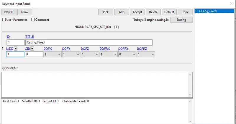
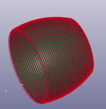
a.Engine casing
Fixing the degrees of freedom for the engine casing as a single ponit constrains.
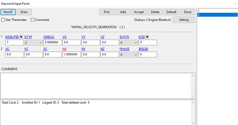
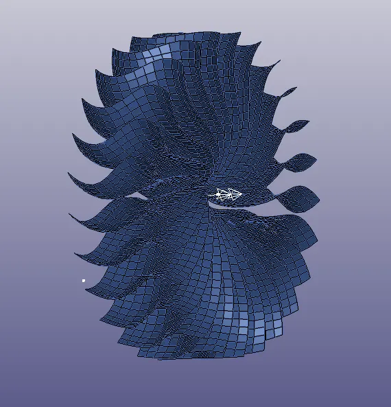
b.Engine Blade
We will assign the Initial velocity generation of Omega(w)= 0.5 rad/ms.
Assume the speed of the blade is nearly 5000rpm then
2⋅π⋅N60=2⋅π⋅5000602⋅π⋅N60=2⋅π⋅500060 = 523 rad/s = 0.523 rad/ms = 0.5 rad/ms.
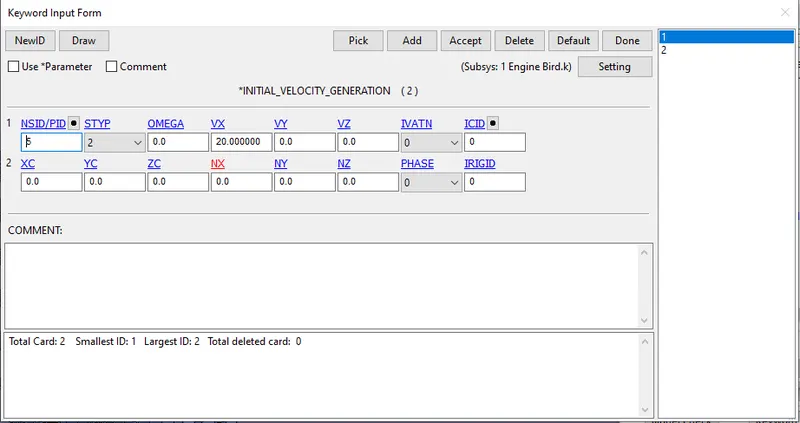
c.Engine Bird
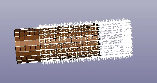
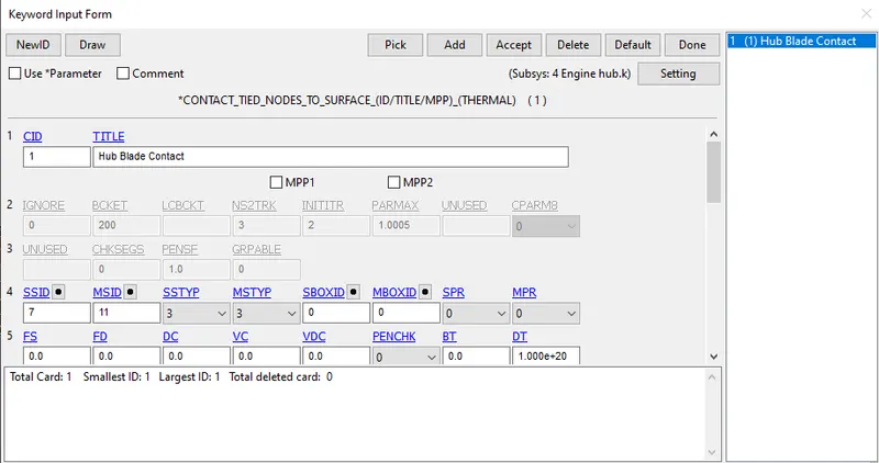
6.Now apply the contacts for the different components as shown.
a. Contact between Hub and Blade
Here give the slave as blades and master as hub.
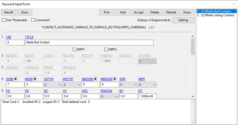
b. Contact between Blade and bird
Here give the slave as blades and master as bird.
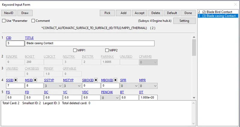
c. Contact between blade and casing
Here give the slave as blades and master as casing.
d. Contact for blade ie, self contact
Here take the slave as blade.
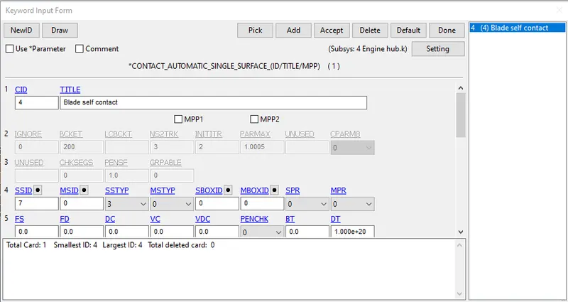
7.Now define the control cards for energy.termination and time step as shown.
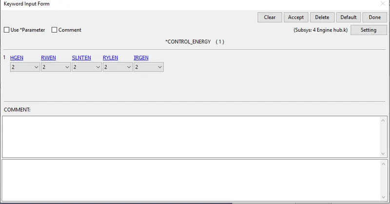
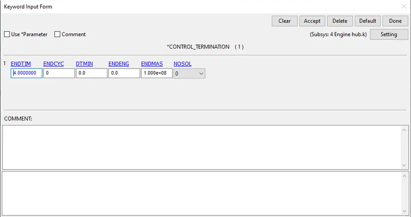
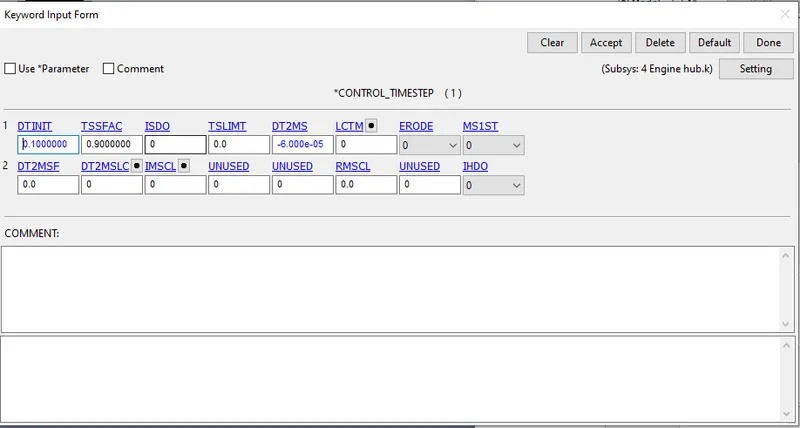
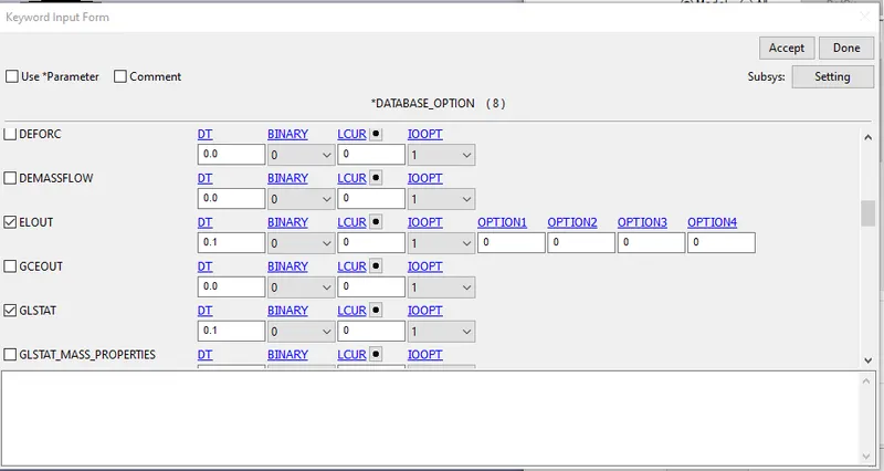
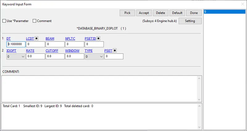
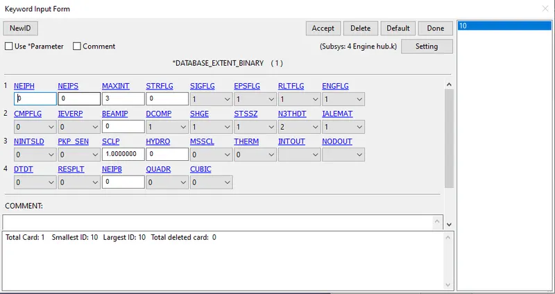
8.Now define the database cards such as ASCII, D3PLOT, EXTENT_BINARY for the requirement of output results.
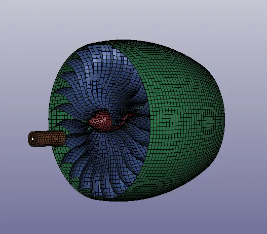
9.Now include all the single different components into a single keyword file as shown in below fig.
Results:
a. In 1st trial, we did this by keeping DT2MS = -6.0E-05 and TSSFAC=0.9 the runtime estimated is 1 hrs 27 min but actually it took 6 min 50 sec
with 0% mass addition.
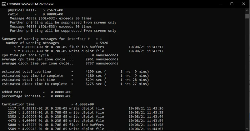
Fig: Estimated data before the simulation run
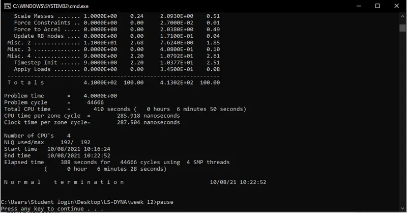
Fig: Final data after the simulation run
b. In the 2nd trial, we did this by keeping DT2MS = -6.0E-04 and TSSFAC=0.9 the runtime estimated is 13 min but actually it took 1
min 24 sec with 2.42% mass addition.
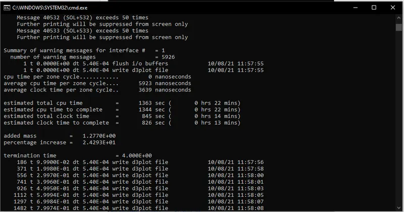
Fig: Estimated data before the simulation run
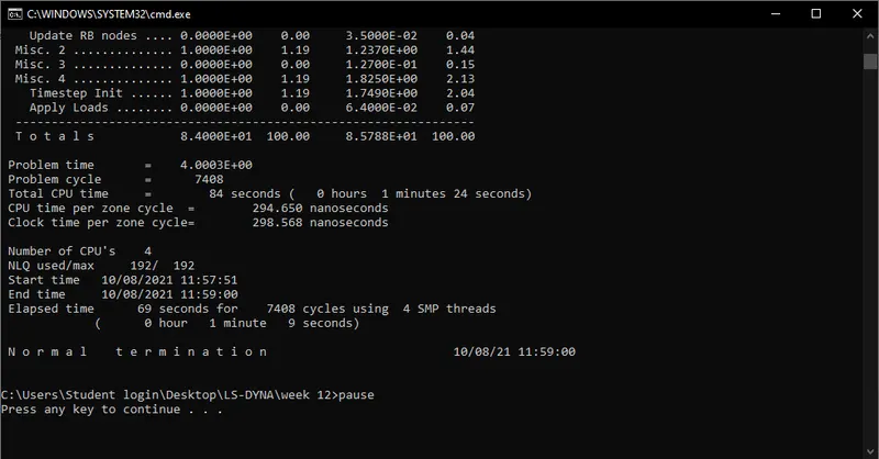
Fig: Final data after the simulation run
c. In the 3rd trial, we did this by keeping DT2MS = -4.0E-04 and TSSFAC=0.9 the runtime estimated is 20 min but actually it took 1 min 55 sec
with 6.6% mass addition. (Acceptable)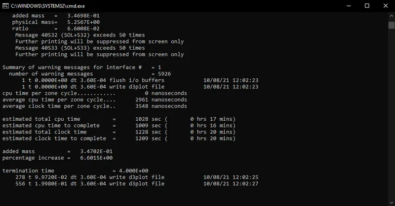
Fig: Estimated data before the simulation run
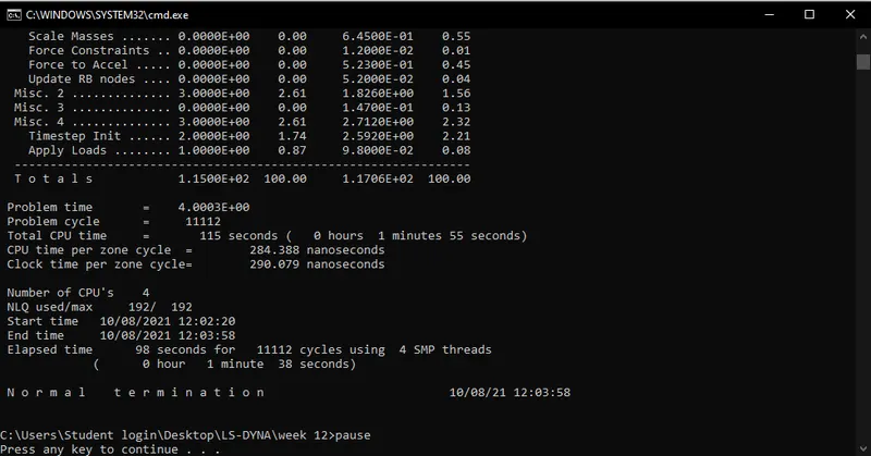
Fig: Final data after the simulation run
Energy Plots:
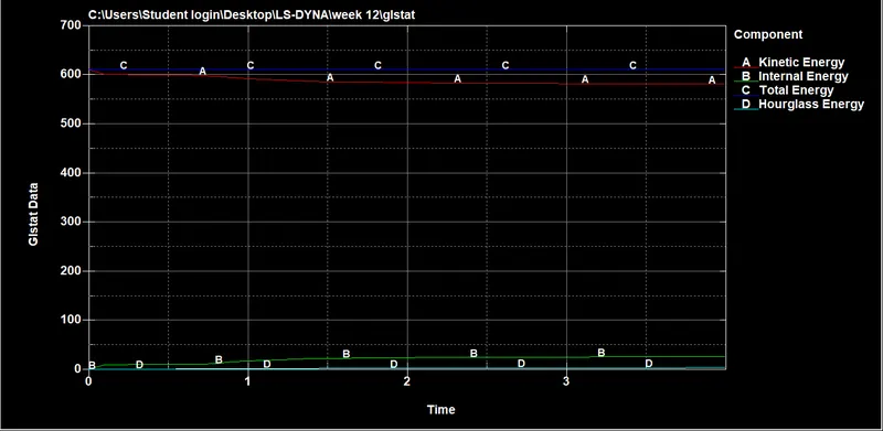
Von-mises stress plot
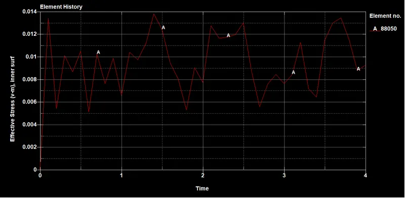
This stress plot is taken on one of the element of the blade where the impact takes with the bird at every time, but the stress peaks and reaches a
value of 0.0796 Gpa at the (time of 2.2 ms )moment of impact and drop to a value of 0.01 Gpa at the end of the simulation.
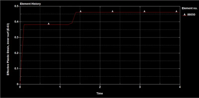
Plastic strain plot
This strain plot is taken on one of the elements of the blade where the impact with the bird. At t= 2.3ms the strain values peak to 0.0935 i.e.
9.35% strain then is constant throughout the simulation.
Contact plot(blade_Bird)
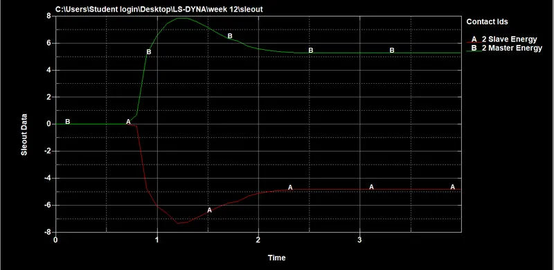
The energy plot between the blade and bird contact is shown below, that before the interaction of the surface the energy was zero but nearly from
1ms the energy within the contact starts to develop. The energy conversion between the slave(blade) and master(bird) is symmetric. the
maximum value of energy developed is 7.86 units at t= 1.20 ms.
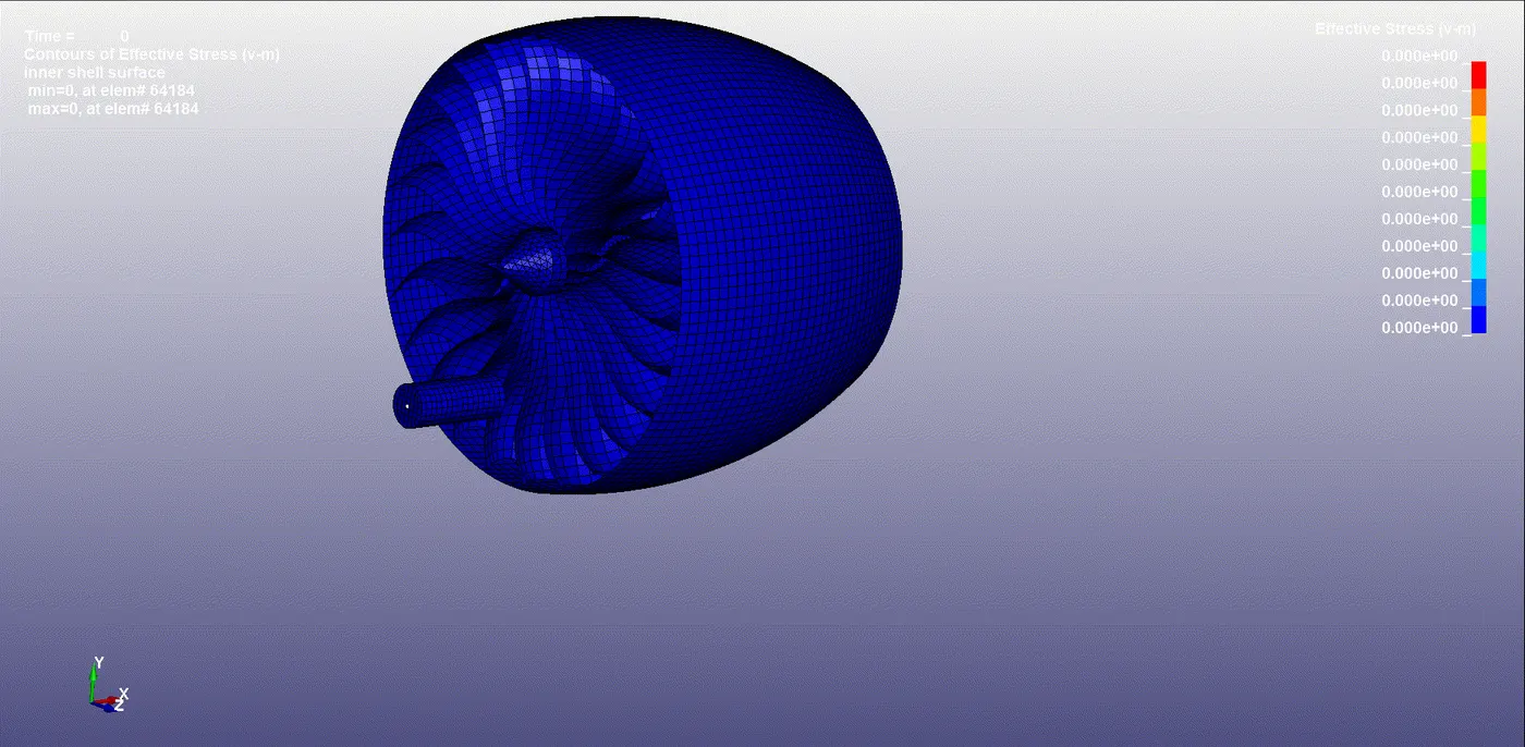
Von- Mises Stress animation for Bird- Strike Impact.
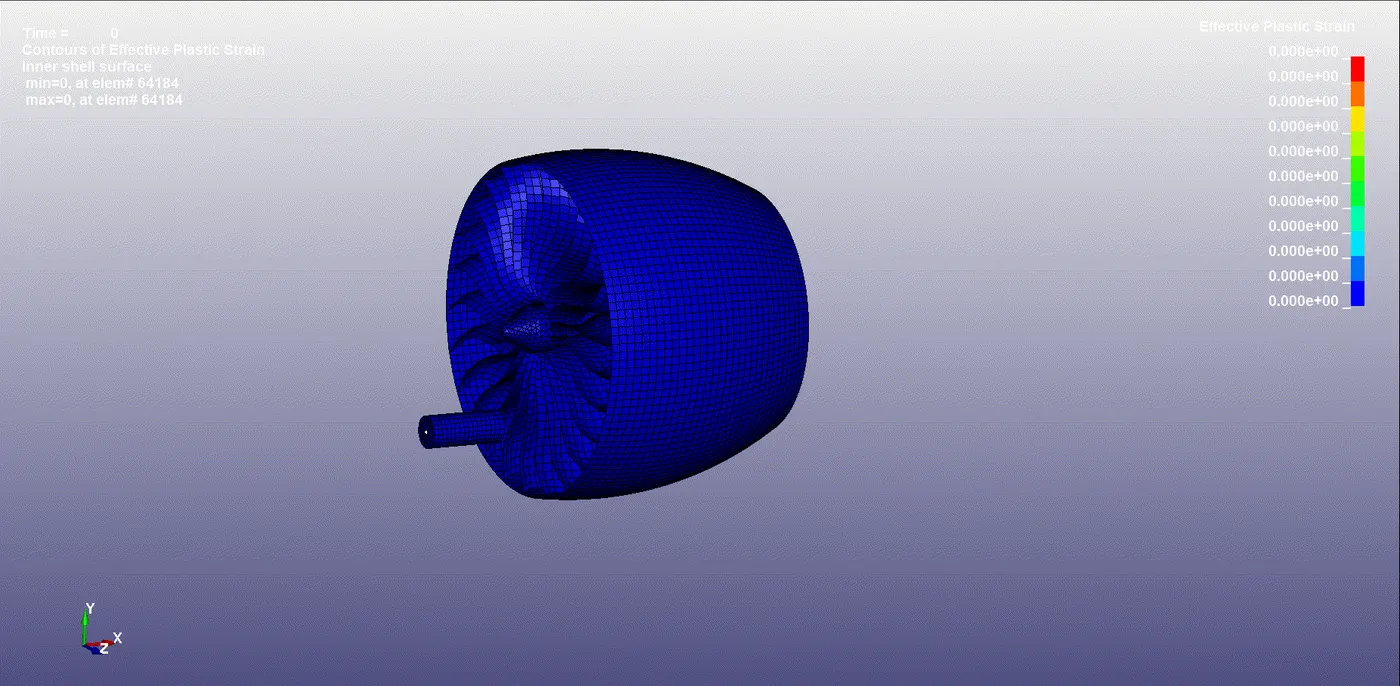
Effective plastic Strain animation for Bird- Strike Impact.
CONCLUSION:
1.All the components are following a consistent number pattern for each element, node, and part, as followed in many industries, and all the files
such as for parts, Boundary conditions, contact, Material card, control, database, are included in the Main file also the Boundary conditions and
initial velocity conditions are deployed in the same real-world scenario.
2.From the energy plot, we can observe that total energy is constant over the simulation which represents the simulation runs well.
3.The max V-M stress produced in the fan blade is 0.0796 Gpa at nearly 2.2ms of simulation
4.The max strain developed is 0.0935 at 2.3ms of simulation and remains constant over the simulation
5.For Mass-scaling, the mass added is 6.67% which below the accepted range ie, 7%.