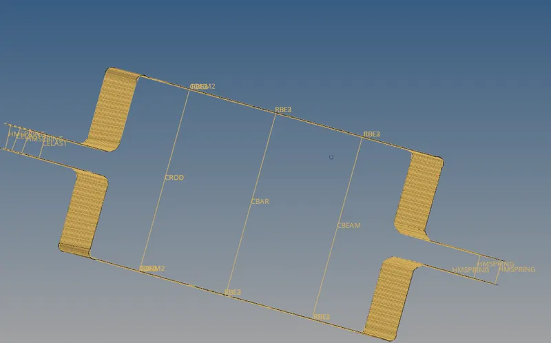
Week 4-1D Element Creation Challenge
1A.
1.
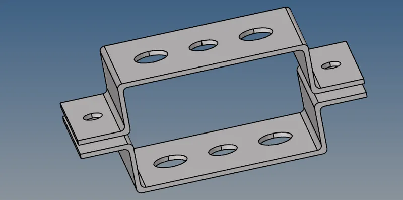
TITLE:Importing the given model.
STEPS:1.Firstly import the model into the workspace.
2.Select the import button on the toolbar and click on the import geometry.
3.Click on the files button to view the model and select on it.
4.Click on the import,then it will be shows on the workspace/graphic area.
5.Firstly the imported geomentry will be in the wireframe.But we must be converted into shaded.
OUTPUT:
2.
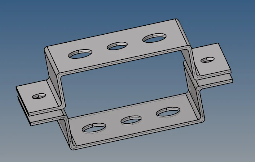
TITLE:Creating the mid surface on the given component.
STEPS:1.Click on the geometry(geom)button on the main menu.
2.Select the midsurfaces option in it.
3.Select auto midsurfacesand then click on the extraction option and set it to the offset+planes.
4.And now go to auto extraction.Click on the surf and select the surface which we want to create the mid surface and click on the extract.
5.The midsurface will be displayed on surface on the component.
6.Repeat the above steps for another component also.
OUTPUT:
3.
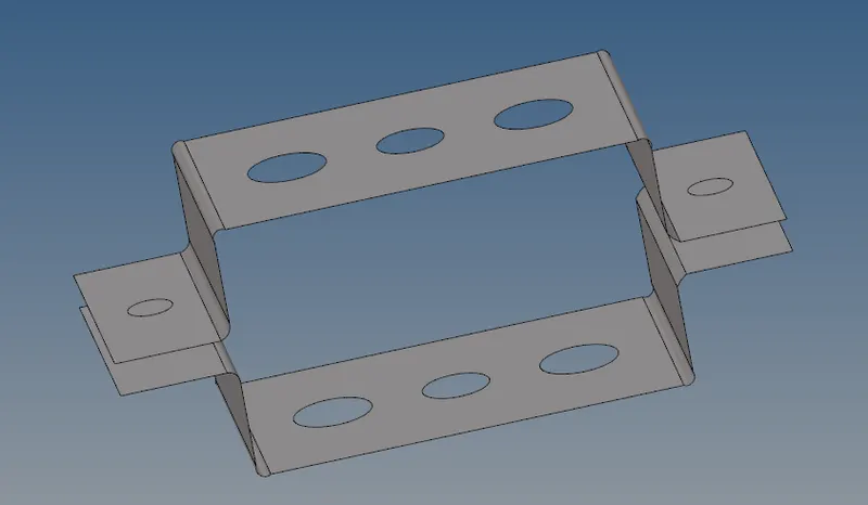
TITLE:Deleting the solid parts from the component.
STEPS:1.Select the delete option on the toolbar.
2.Set the solid click on the solid select all.
3.Click on the delete entity,then the solids are removed.
OUTPUT:
4.
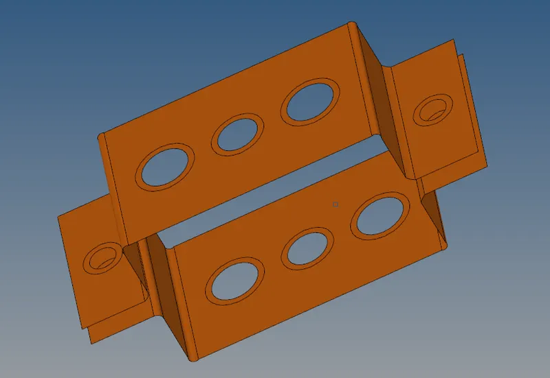
TITLE:Creation of washer split on component.
STEPS1.Click on the geometry(geom)button on the main menu.
2.Click on the quick edit button.
3.Select washer spilt and give offset value as 5 units.
4.click on the lines that we want to washer split,then it will be displayed.
OUTPUT:
5.
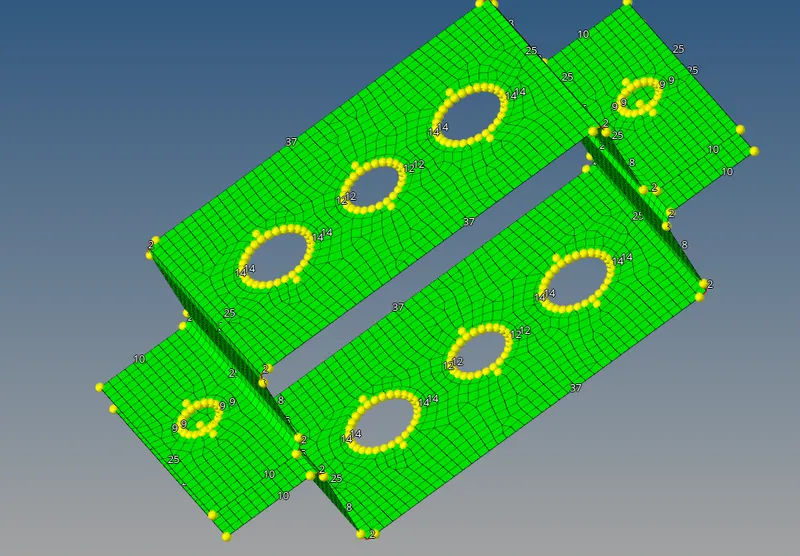
TITLE:Creating the mesh for the object.
STEPS:1.Select the 2D option in main menu bar.
2.Select the auto mesh and click on all the surfaces in the display and give the element size as 5.
3.Click on the mesh type ans set it as the mixed one.
4.Click on the mesh button,then it will be gonna mesh the componenet.
5.Click on the return button.
6.Go to components section and delete the first three components.
7.To rename the midsurface is bracket 1 and another bracket 2.
OUTPUT:
6.
TITLE:Creating the material and properties.
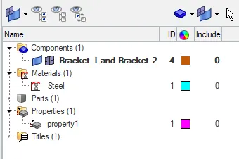
STEPS:1.Click the mouse right button on components section and select the material to add it for the component.
2.For the creating of the properties follow it as mentioned in the above step.
3.It will be renamed to bracket1 and also create another property as bracket2.
4.set the properties to required specifications.
OUTPUT:
7.
TITLE:Creation of RBE2,RBE3 links on the components.
STEPS:1.Select the 1D in main menu bar.
2.Select the rigid and select calculate nodes,click on the nodes and make it by the path.
3.Click on hole and washer nodes are totally select.
4.Click create it is shows on display.
5.Repeat the same steps for the remaining five holes.
OUTPUT:
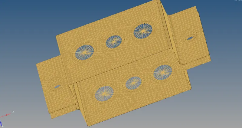
RBE2 is used for uniform load distributed.
RBE3 is used for non-uniform load distributed.
8.
TITLE:Creating the box,I-section and cross section.
STEPS:1.Select the 1D in main menu bar
2.Click on the hyper beam and select the standard section click on the hyper beam and selection type our requirements it will be chosen
3.Select the given sections and give specific dimensions for all.
4.Next click on the view model it will be coming back.
OUTPUT:
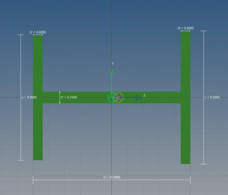
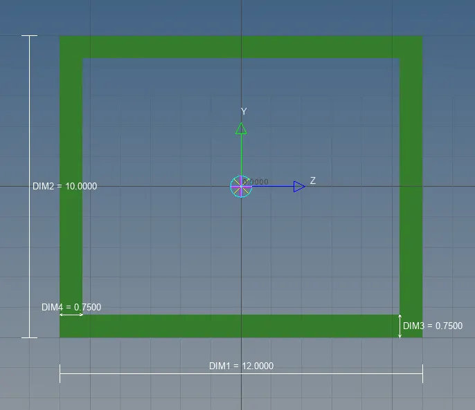
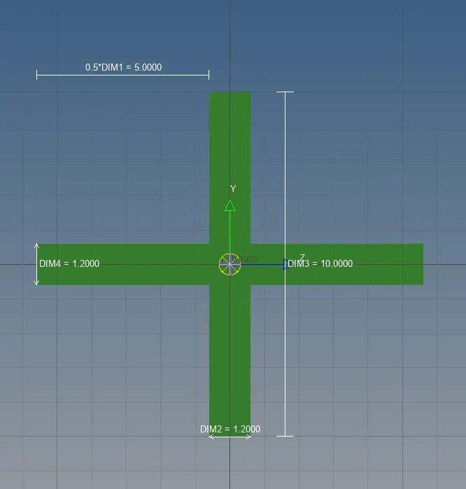
9.
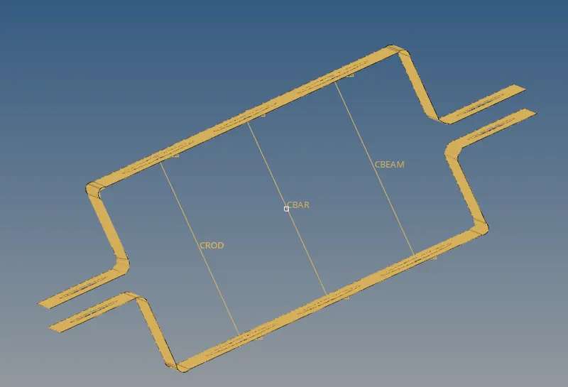
TITLE:Creating the rod element,beam element and bar elements.
STEPS:1.Select the 1D option from the main menu bar.
2.click on the rod and select node A &node B and select element type CROD it shows on screen.
3.Click on the return button.
4.Select the bar and click on the nodes.
5.Select the element type CBEAM for beams,and CBAR for bars.
6.Click on return.
OUTPUT:
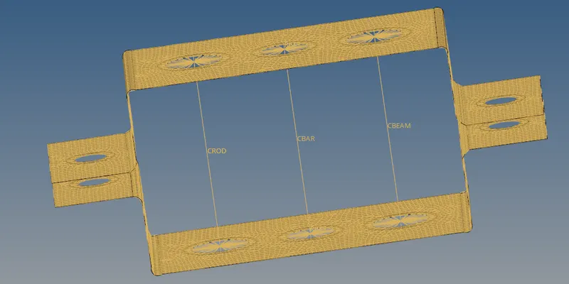
10.
TITLE:Update the rod element,beam element and bar elements.
STEPS:1.Set properties of rod,beam and bar.
2.Go to update the elements.
3.In 1D select the rod click on the element and set property element type option.
4.Click on the update,then it shows updated.
5.Repeat the same process for beam and bar elements.
6.Click on the return button.
11.
TITLE:Rod element,beam element and bar element vissible.
STEPS:1.Set the properties of rod,beam and bar members.
2.Go for update the elements.
3.In 1D select the rod click on the element and set property element type.
4.Click on the update it shows updated.
5.Repeat the same process for beam and bar elements.
6.Click on the return and go to tool bar select 1D detailed representation.
7. The rod,beam and bar is shows on graphical area.
OUTPUT:
12.
TITLE:Creating masses at ‘e’ points.
STEPS:1.Select rigid and create RBE2 as shown in above points.
2.Go to masses and click on the RBE2 node give mass 10.
3.Click on create it will be applied mass.
4.Repeat the steps for another side point.
5.Click on return.
13.
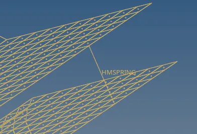
TITLE:Create springs at ‘f’ point.
STEPS:1.Select 1D on the main menu bar.
2.Go to springs select the node 1 & node 2.
3.Click on the element type it will be HMspring and click on the create.
4.It will be display the screen.
5.repeat the steps for another side.
6.Click on return.
OUTPUT:
14.
RESULT: