Week-6 Calculate the Stretch Ratio by comparing the ELFORM (-2,-1,1,2) with Ogden_Material Model.
Aim:
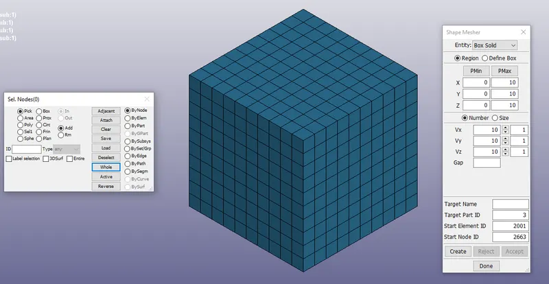
1. A creation of block with dimensions of 10mm*10mm*10mm which consists of 10 elements and assign the material card given in the challenge
to run the simulation on the box.
2.By using on the appropriate conditions boundary conditions apply the tensile load on the created box and compare the results obtained from the
analysis above upto strech ratio 5.
3.Also compare the results for the analysis using ELFORM = 1,2,-1,-2
Procedure:
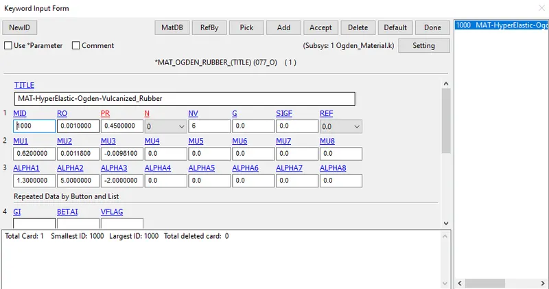
1.Open the LS_Dyna software and import the given .k file which is given in the challenge with assigned Ogden_Material as shown in the below
fig.
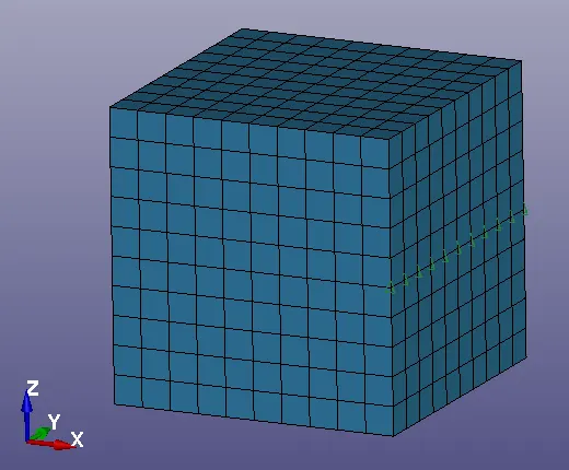
2.Now create a box by going in to the element and mesh deck and select the shape mesher.In it give the required dimensions as mentioned above
and click on create and accept the box to create it.
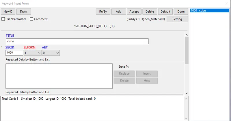
3.Now create a section_solid card for the box/cube as shown in the below image.
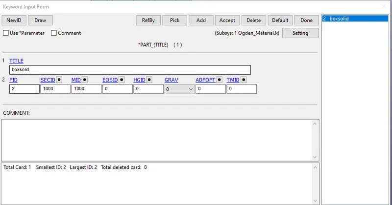
4.Now arrange the both the material and section solid cards in the created part as shown in the below fig.
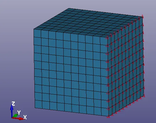
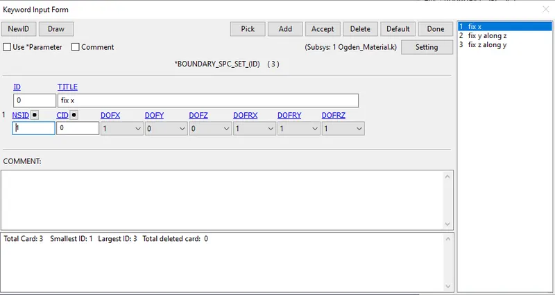
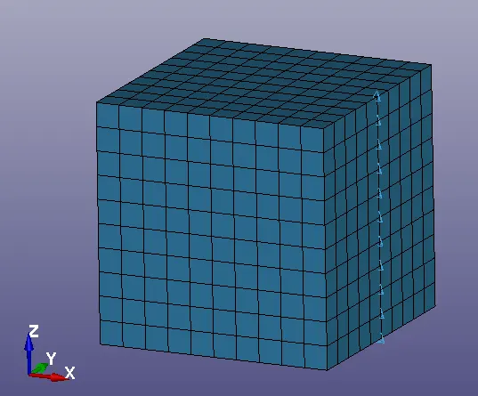
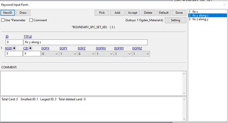
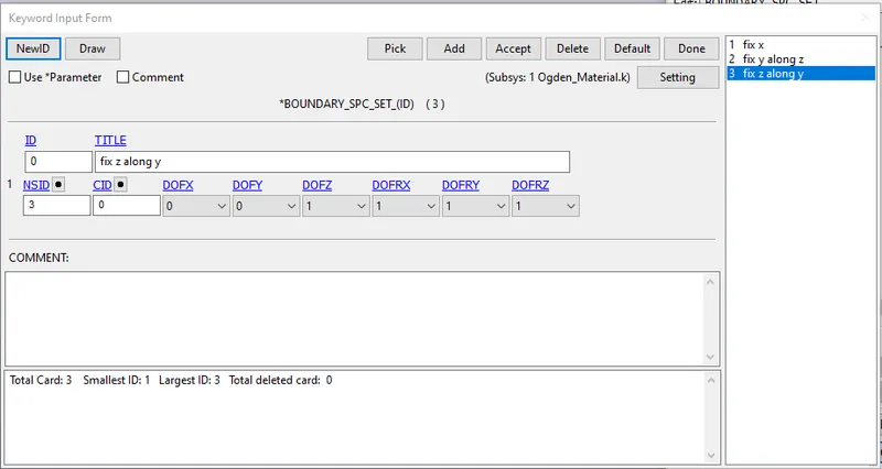
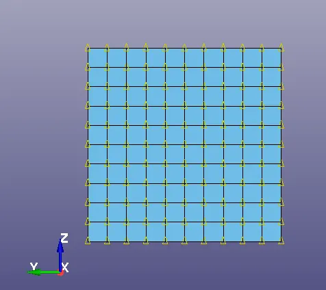
5.Now create the Boundary conditions as SPC_SET to make the box to be constrained as per the required directions and the sets are shown in the
below fig.
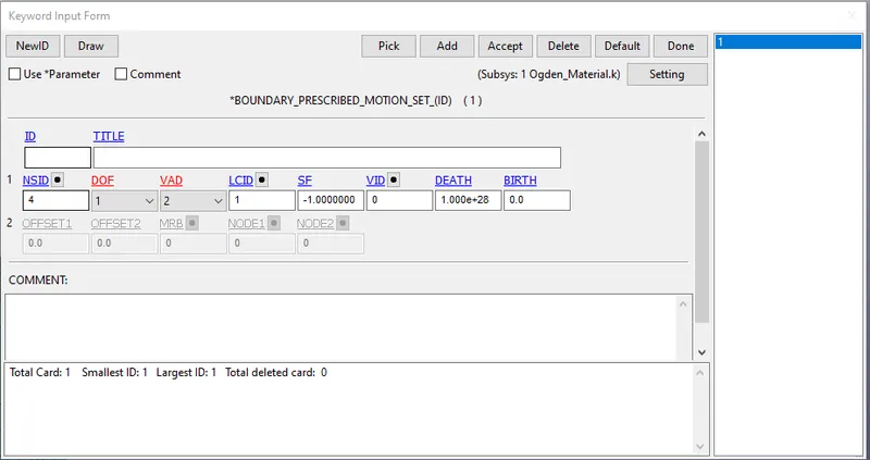
6.Now create a displacement card from the boundary prescribed motion set and select the nodes to move for the application of displacement as
shown in the below fig.
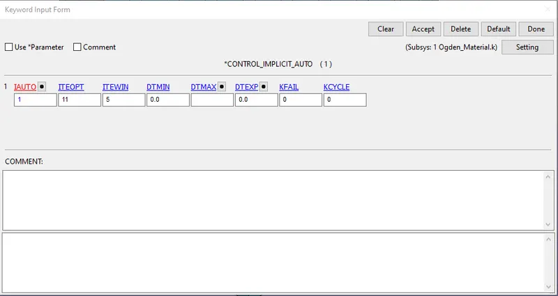
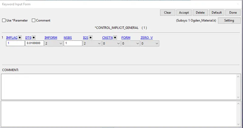
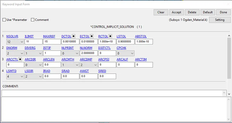
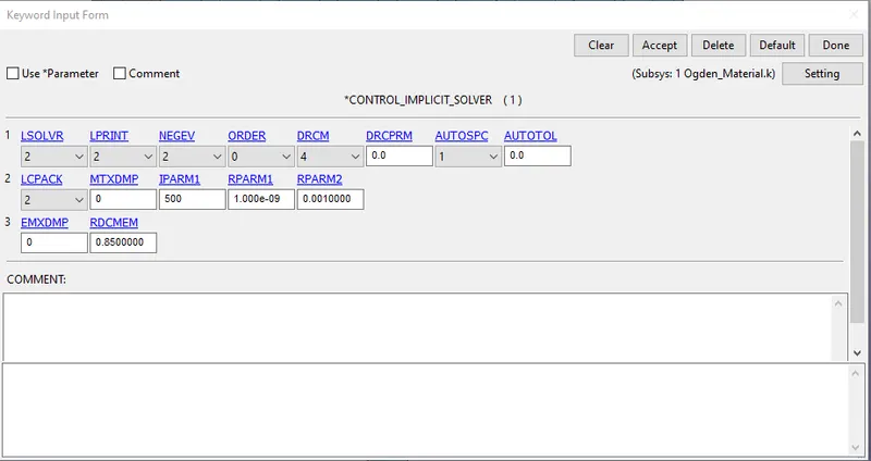
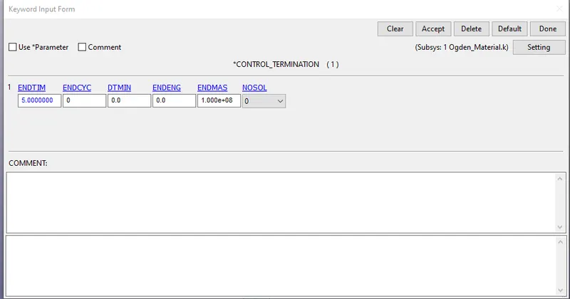
7.Now for the non linear implicit analysis we need to create some implicit cards that are shown in the below fig.
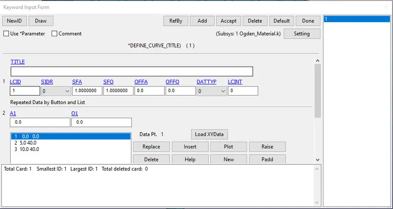
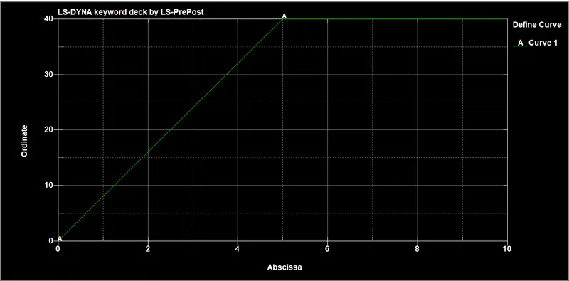
8.And now define a displacement curve and arrange the values as shown in the below fig.
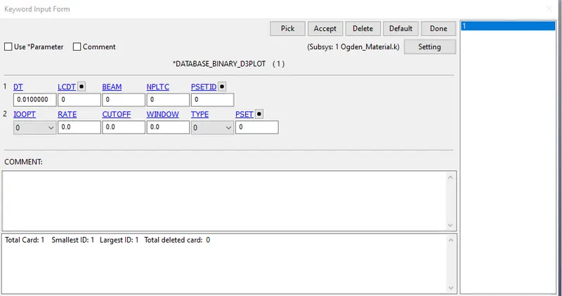
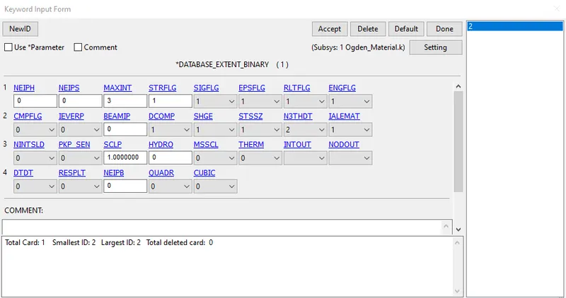
9.Now create some output cards for plotting the various aspects as shown in the below image.
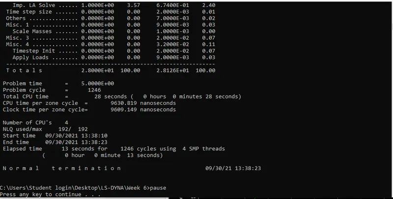
10.Now run the simulation by using the LS-Run application and the simulation results are shown in the given fig.
11.Now do the same steps for the element formulation for -1,2,-2.
Results and Discussion:
1.After running the file in the LS manager open the output d3plot file in the pre-post manager and run the animation.
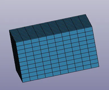
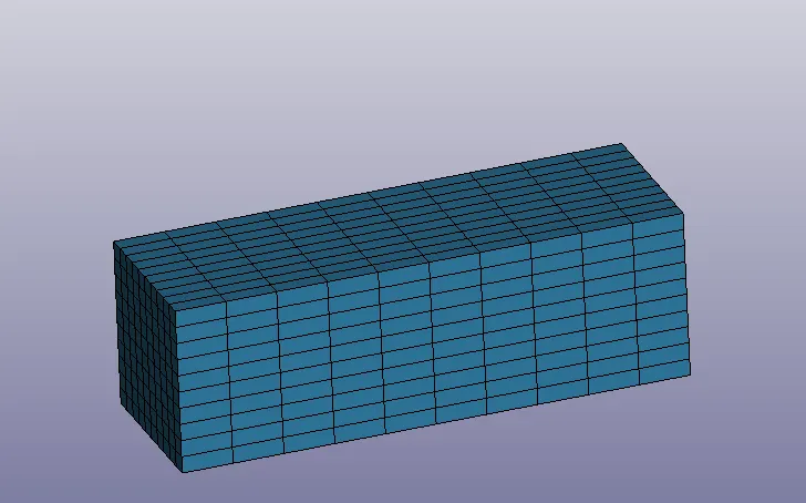
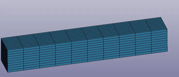
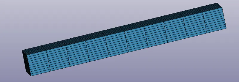
2.Here we can see the stress on the box while applying the tensile load on it.
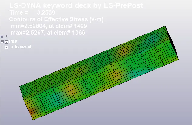
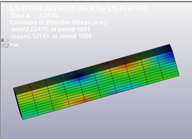
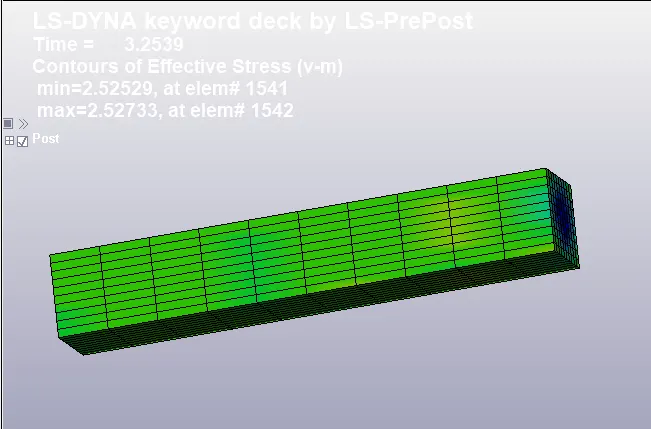
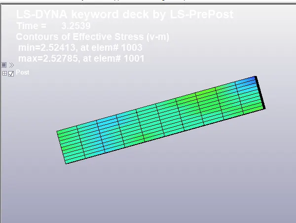
3.To extract the true stress and true strain, go to the history deck and select the element option and select the element by manually and select the
plot option and save the plot data in .xml format.
4. Now we extracted the true stress and true strain with help of below formulas. we can find the values and plot the graph.
E =ln(e+1) where E = True strain and e = Engineering strain
St = Se*(1+e) where St = True stress and Se = Engineering stress
Stretch Ratio = e+1 and Normal stress = True stress/Stretch ratio.
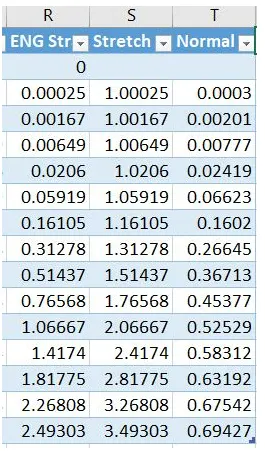
5.With the help of above data we can plot the graph Normal stres vs Stretch ratio.
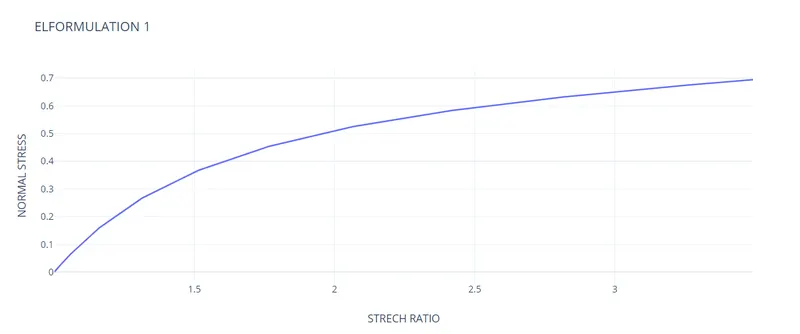
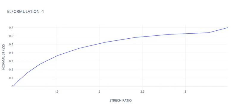
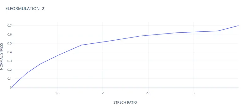
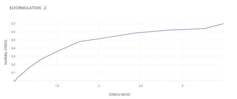
As we can see we have applied uniaxial tension on the cube and the stretch ratio is increasing exponentialy with respect to the normal stress.
Conclusion:
Thus we have done a simulation on the Ogden material cube with uniaxial tensile load and find out the engineering stress and strain and stretch
ratio and plotted the graph of Normal stress vs stretch ratio.