Week 6-Meshing of Hood Challenge
Aim: Meshing the component given and assigning the thickness to that component by giving the target Element Length as 5 Units by using of the quality criteria as mentioned below.
| S.N | Quality Criteria | Value |
| 1 | Aspect Ratio | 5 |
| 2 | Skewness | 45 |
| 3 | Warping | 15 |
| 4 | Taper | 0.5 |
| 5 | Min. Length | 2 Units |
| 6 | Max. Length | 8 Units |
| 7 | Min angle Quad | 45 |
| 8 | Max angle Quad | 135 |
| 9 | Min angle Tria | 20 |
| 10 | Max angle Tria | 120 |
| 10 | Tria % | 10 |
Steps:
1.Firstly import the model.
2.Select the import option on the toolbar menu and click on the imported geometry.
3.Click on the file sign,then it will be shown the model and then select it.
4.Click on the import button,then it will be shown on the graphic area.
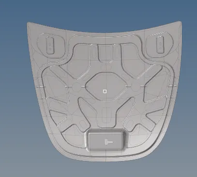
5.After importing the geomentry model,hide all the surfaces of the components.
6.Now unhide the one of the surfaces of the geomentry called inner extract.After unhiding it,click on the mid surface option from the geomentry menu bar.
7.After clicking on the mid surface,goto extraction option and select the skin offset which gives the perfect mid surface for the component.
8.After selecting it,go to the auto extraction and click on the surfaces which we have to perform the mid surface operation and click on the extract button to perform the operation.
9.After creation of the mid surface,perform the autocleanup operation on the surface of the component for the cleaning of the entire geomentry on the component.
10.Before starting up the mesh,adjust the elemental quality criteria as mentioned above in the procedure.
11.The quality criteria can be adjusted from the preferances option from the main menu bar.
12.After that split the component into the desired number of parts which we can perform the mesh properly.
13.After spiliting into the parts, perform the automesh operation from the 2D in the menu bar.
14.Now while performing the meshing,ignore all the rotational quadrant that are which cannot be formed during the mesh.
15.Repeat the same steps for the remaining components in the geomentry model.
16.The below figures will shows the each components of the model after meshing.
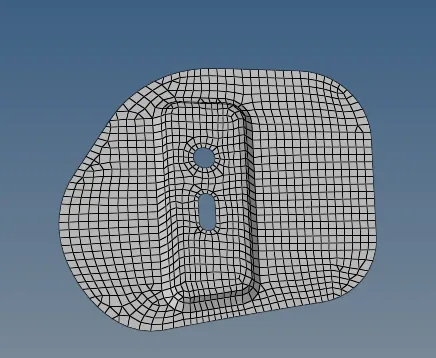
Fig.1.HINGE
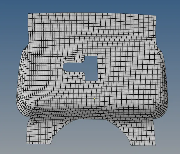
Fig.2.LATCH
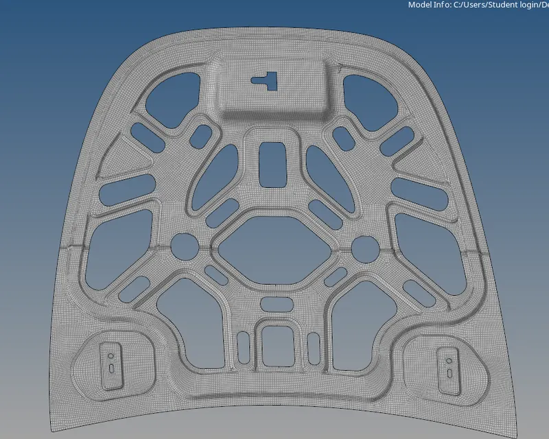
Fig.3.INNER EXTRACT BODY
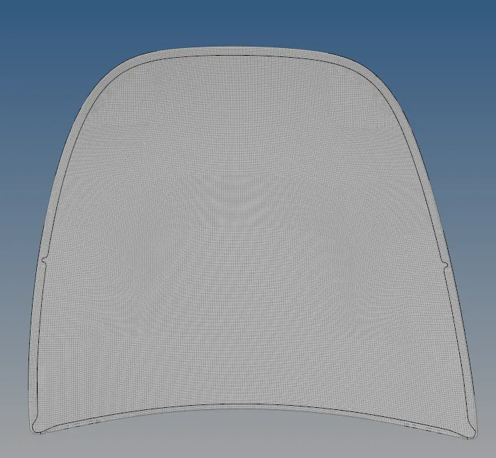
Fig.4.OUTER EXTRACT BODY
17.After meshing the all above components the entire model be shown as in below fig.
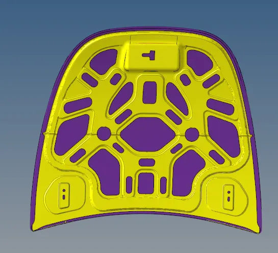
OUTPUT
18.Thus I performed quality criteria for meshing the given component with the given element thickness as 5 units.