Week 8 Worm Gear Challenge
Objective:
For this model we have to analyze a transient structural analysis on a worm gear assembly.We can use a finer mesh while performing the
challenge.
PROCEDURE AND EXECUTION:
1.Open the ANSYS workbench in the system.
2.After opening the workbench,double click on the Transient structural and rename it as Worm_Gear.
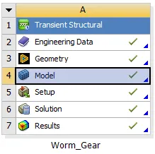
3.A table is displayed on the workbench,In it double click on the engineering data to edit for adding the material Structural steel.
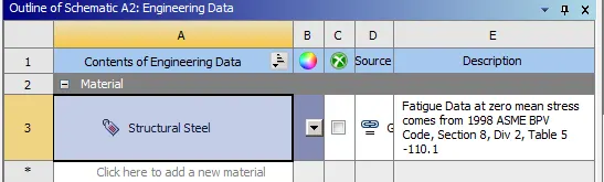
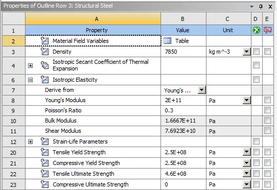
4.After assigning the data,close the engineering data and perform right click on the geomentry.
5.Import the given geomentry as given above and click on update on the model.
6. To check the given geomentry right click on it and it will open into the space claim to view the geomentry.
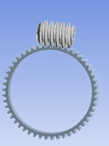
7.After checking the given geomentry close the space claim and open the model by double click on it or it can be opened by right click on the
model and select edit option to start the mechanical module to open.
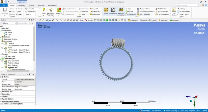
8.After opening the mechanical module,on the left side we can see a tree filter which contains all the components of the geomentry.
 .
.
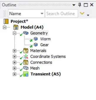
9.In the geomentry,it consists of two components and rename them as based on the components given.
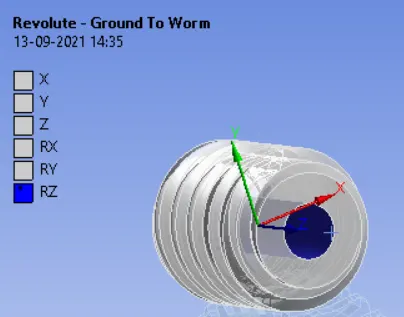
10.In the connections a default contacts has been created so we can just renamed on the basis of geomentry names and change the definition
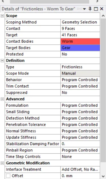
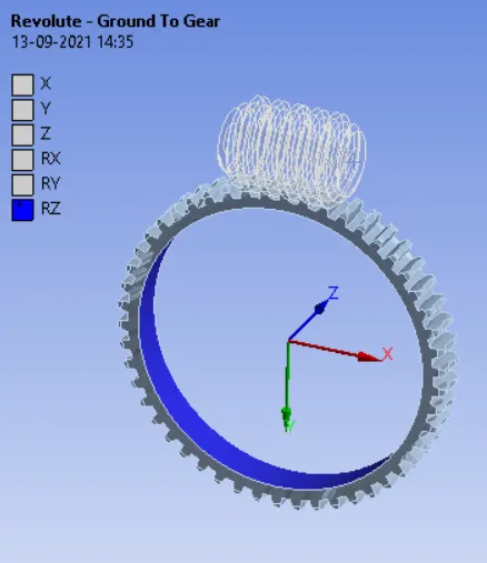
type to frictionless and apply it and also create two revolute joints for both the worm and as well as gear as shown in the below fig.
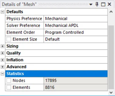
11.Now go to the mesh and change the element size to 2mm which does not exceeds the 31k elements.The generated mesh has the following
number of nodes and elements.
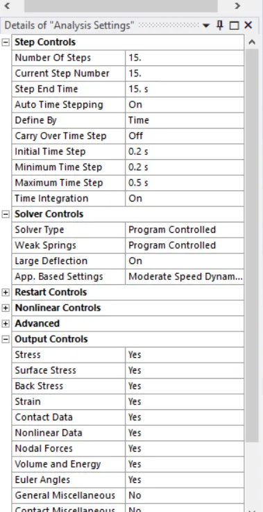
12.In analysis setting,we run the analysis by 15 number of steps as shown in below.
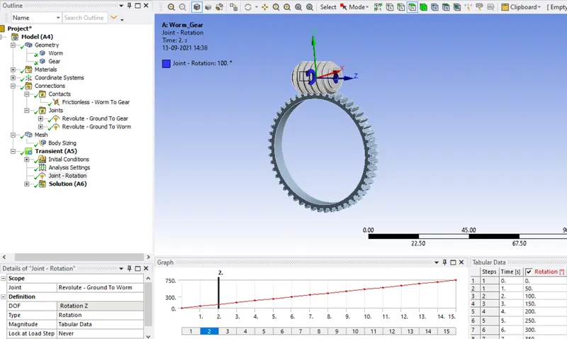
13.Now create a revolute joint by using a revolute joint from the analysis settings as shown in the fig.
14.Now we can ready to run the analysis by right clicking on the solution to solve or by using the F5 key.
Result:
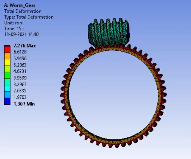
Total Deformation Of The Model
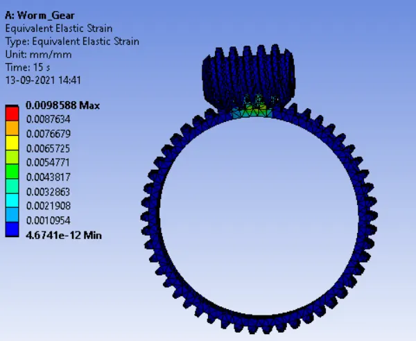
Equivalent Strain Of The Model
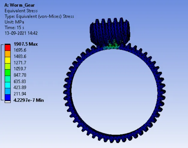
Equivalent Stress Of The Model
Tabulation:
|
Parameters |
Max. Total Deformation (mm) |
Max. Equivalent Elastic Strain (mm/mm) |
Max. Equivalent Stress (MPa) |
|
Worm Gear |
7.276 |
0.0098588 |
1907.5 |
Conclusion:
From the simulation results we can that the area where there will be Max. Total Deformation, Max. Equivalent Elastic Strain and Max.
Equivalent Stress occurring on the Gear during the simulation.