Week 2 Railwheel and Track
Introduction to Rail Wheel:
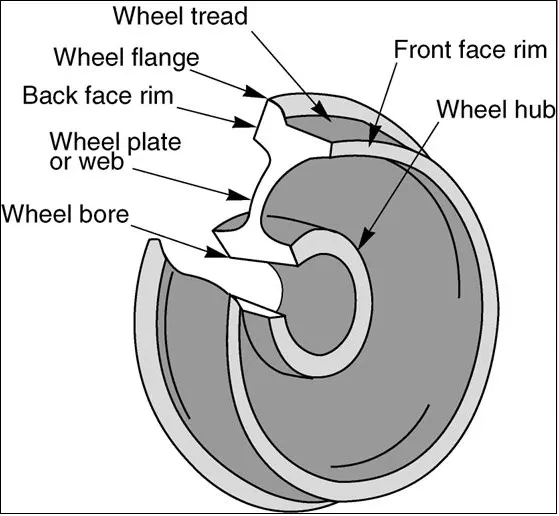
A train wheel or rail wheel is a type of wheel specially designed for use on railway tracks. A rolling component is typically pushed onto an axle and mounted directly on a railway carriage or locomotive, or
Indirectly on a bogie, also called a truck. Wheels are cast or forged and are heat-treated to have a specific hardness. New wheels are trued, using a lathe, to a specific profile before being pressed onto an axle. All wheel profiles must be regularly checked to ensure proper interaction between the wheel and the rail. Incorrectly trued, or worn out wheels can increase rolling resistance, reduce energy efficiency and may even cause a derailment. A railroad wheel typically consists of two main parts: the wheel itself, and the tire (or tyre in British English) around the outside. A rail tire is usually made from steel, and is typically heated and pushed onto the wheel, where it remains firmly as it shrinks and cools. Monobloc wheels do not have encircling tires, while resilient rail wheels have a resilient material, such as rubber, between the wheel and tire.
Rail wheel design can be observed as given below:
Introduction to Rail Track:
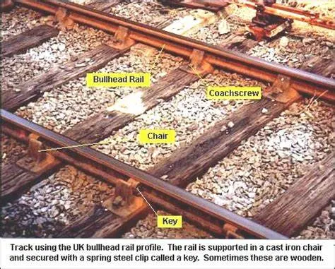
The track on a railway or railroad, also known as the permanent way, is the structure consisting of the rails, fasteners, railroad ties and ballast (or slab track), plus the underlying subgrade. It enables trains to move by providing a dependable surface for their wheels to roll upon. For clarity it is often referred to as railway track or railroad track .Tracks where electric trains or electric trams run are equipped with an electrification system such as an overhead electrical power line or an additional electrified rail.The term permanent way also refers to the track in addition to line side structures such as fences.
Rail Profile:
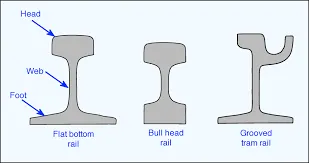
The rail profile is the cross sectional shape of a railway rail, perpendicular to its length. Early rails were made of wood, cast iron or wrought iron. All modern rails are hot rolled steel with a cross section (profile) approximate to an I-beam, but asymmetric about a horizontal axis (however see grooved rail below). The head is profiled to resist wear and to give a good ride, and the foot profiled to suit the fixing system. Unlike some other uses of iron and steel, railway rails are subject to very high stresses and are made of very high quality steel. It took many decades to improve the quality of the materials, including the change from iron to steel. Minor flaws in the steel that may pose no problems in other applications can lead to broken rails and dangerous derailments when used on railway tracks. By and large, the heavier the rails and the rest of the track work the heavier and faster the trains these tracks can carry.
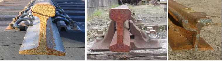
There are so many types of rail profiles. Some of them are listed below:
- Flat bottom Rail
- Bull Head Rail
- Grooved Tram Rail
______________________________________________________________________________________________________________________________________
Analysis
We are interested in structural analysis of Rail Wheel and Track setup.
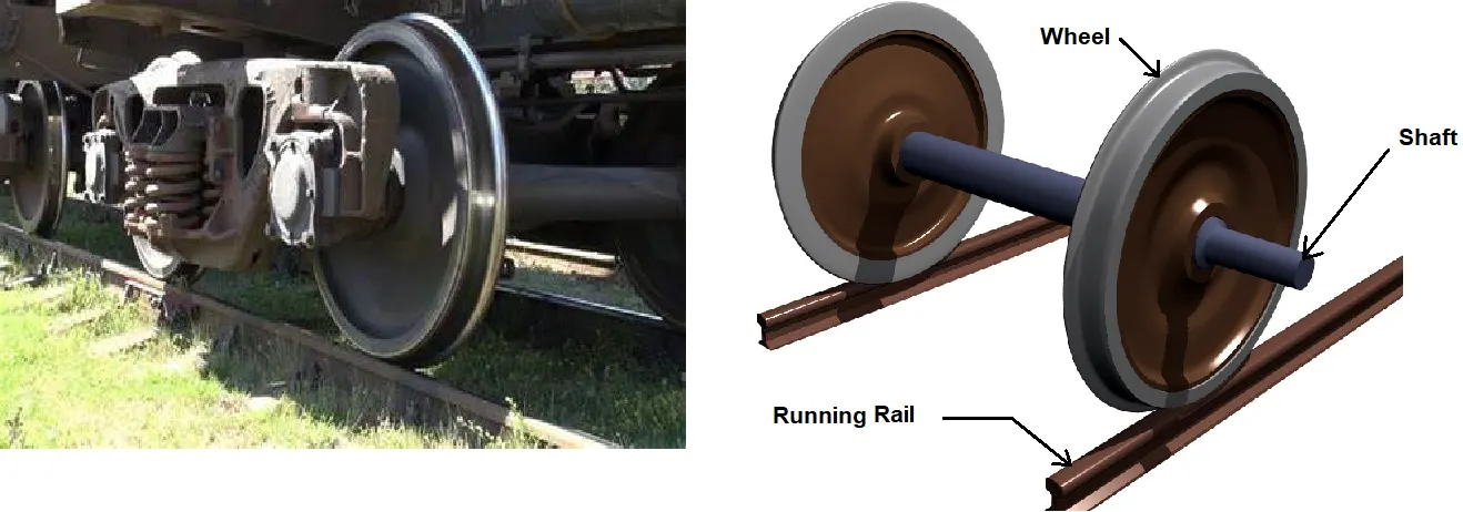
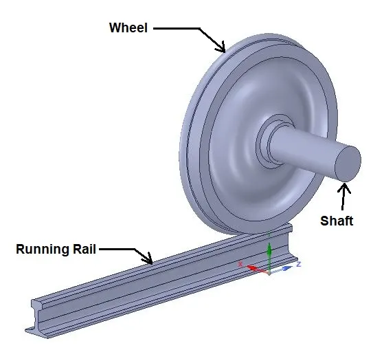
- We can see in above image that wheel is attached with shaft and in contact with running rail.
Due to shaft, there is bearing load acts in the wheel bore.
- We are concerning about stress, strain and deformation variation at different bearing loads.
So cases on the bases of bearing loads are as given below:
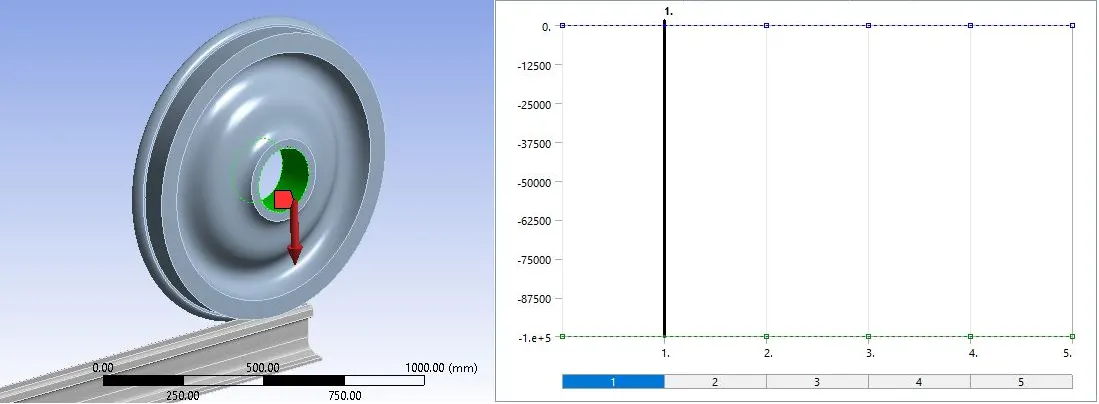
CASE_1: Bearing Load = 100000 N
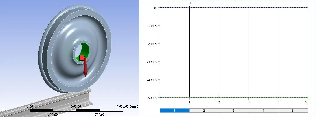
CASE_2: Bearing Load = 500000 N
______________________________________________________________________________________________________________________________________
Geometry:
________________________________________________________________________________________________________________________
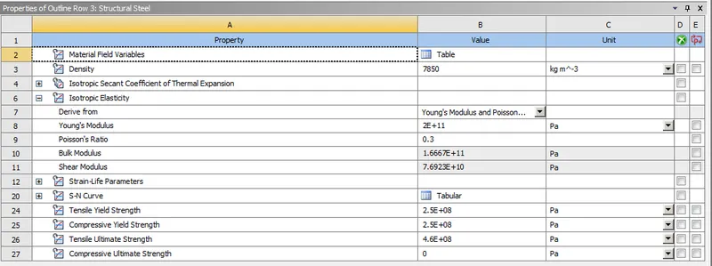
Material Specifications:
________________________________________________________________________________________________________________________
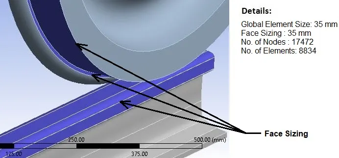
Mesh:
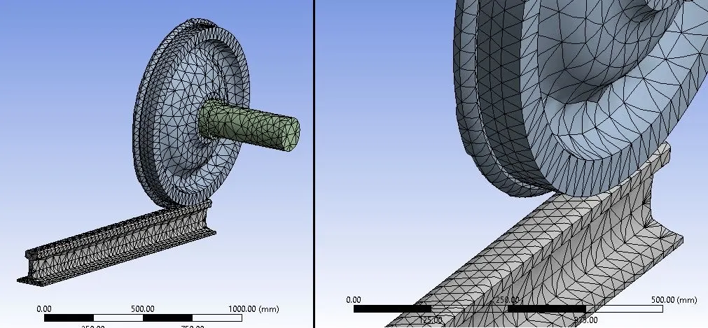
Mesh Details:
________________________________________________________________________________________________________________________
Procedure:
- Import model “Skill_Lync_Railwheel_Track.x_t” in geometry.
- In model, check or set the names of components as “Running Rail”, “Wheel” and “Shaft” as per geometry.
- By default material is “Structural Steel”.
Connections:
- Make contacts based on definitions.
Contact_1:
Contact Body = Wheel
Target Body = Running Rail
Type: Frictional
Friction Coefficient: 0.3
Contact_2:
Contact Body = Shaft
Target Body = Wheel
Type: Frictionless
Joints: Joint_1
Connection Type: Body-Ground
Type: Fixed
Body: Running Rail
Joint_2
Connection Type: Body-Ground
Type: Translational
Body: Shaft
Joint_3
Connection Type: Body-Ground
Type: Planar
Body: Wheel
Boundary Conditions:
- After meshing as described above, create Boundary Conditions as given below:
Analysis Settings:
No. of Steps = 5
Solver Type: Direct
Output Controls: All “Yes”
Non Linear Controls: Force Convergence: ON
Time Step Controls:

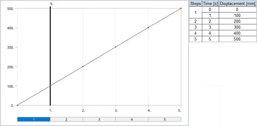
- Here we want Wheel to translate on Running Rail up to distance 500 mm with 100 mm on each step.
- Also there is a load imposed by a carriage transferred to shaft and from shaft to Wheel through Hole.
So, Other Boundary conditions for joints are as given below:
For CASE_1:
Bearing Load:
Direction: -Y (Negative)
For CASE_2:
Bearing Load:
Direction: -Y (Negative)
For CASE_1 & CASE_2:
Joint Displacement:
Joint: Translational – Ground to Shaft
Type: Displacement
Magnitude: Tabular Data
Tabular Data:
Solution:
- After giving proper boundary conditions, create desired solutions for output results.
- Create Solutions for “Equivalent (Von Mises) Stress”, “Equivalent (Von Mises) Strain” for over all setup and for Wheel and “Total Deformation”.Also create solution for “Fatigue Life”.
_______________________________________________________________________________________________________________________
Results:
- Now we will see all results with comparison.
Results for CASE_1 and CASE_2 are as given below:
Stress Contours at Sections:
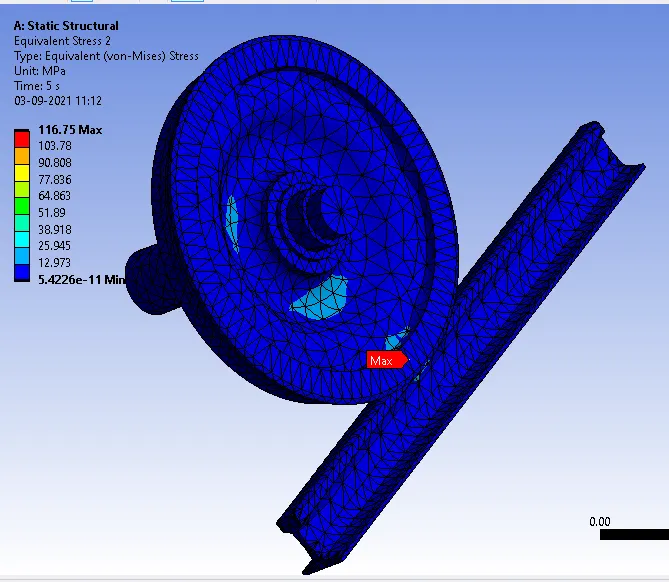
CASE 1
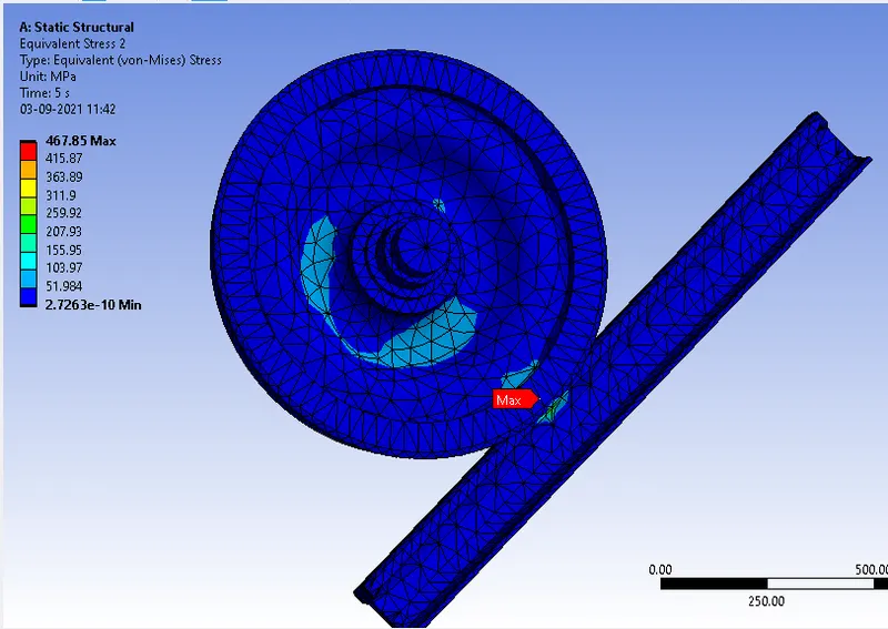
CASE 2
Stress Plots:
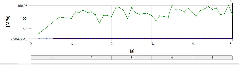
CASE 1
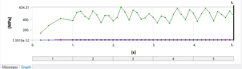
CASE 2
Stress Data:
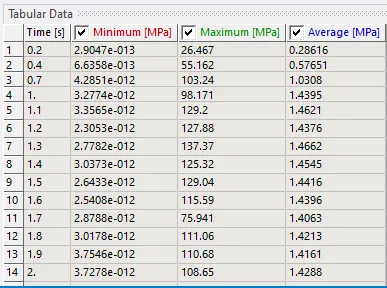
CASE 1
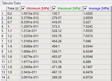
CASE 2
_ _ _ _ _ _ _ _ _ _ _ _ _ _ _ _ _ _ _ _ _ _ _ _ _ _ _ _ _ _ _ _ _ _ _ _ _ _ _ _ _ _ _ _ _ _ _ _ _ _ _ _ __ _ _ _ _ _ _ _ _ _ _ _ _ _ _ _ _
Strain Contours:
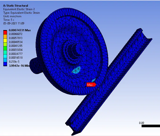
CASE 1
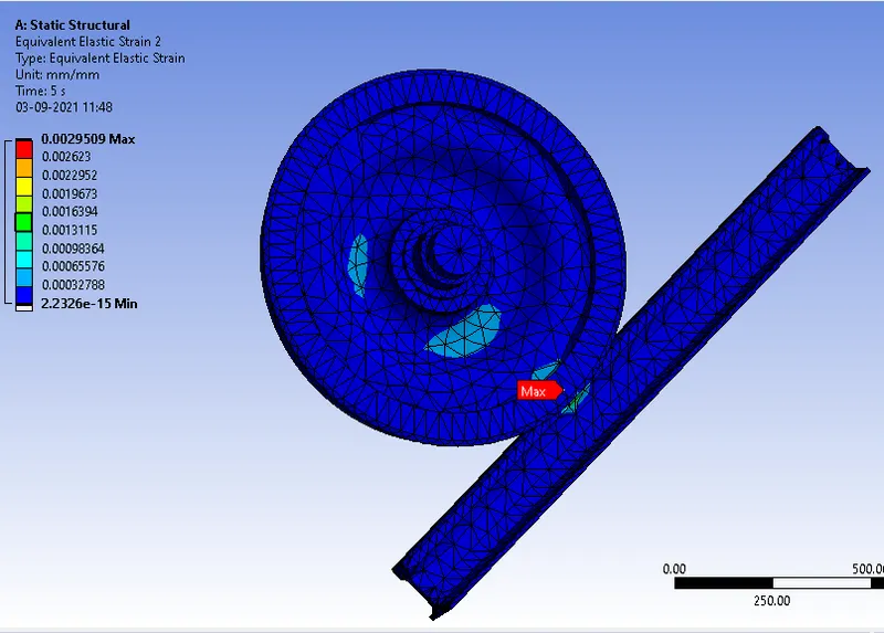
CASE 2
Strain Plots:
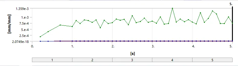
CASE 1
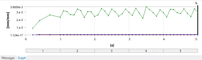
CASE 2
Strain Data:
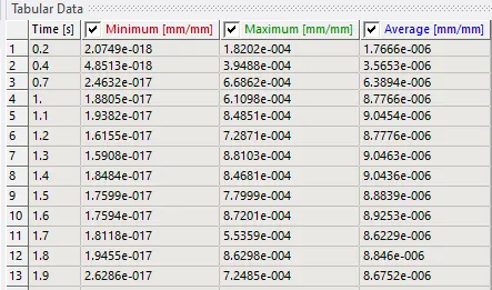
CASE 1
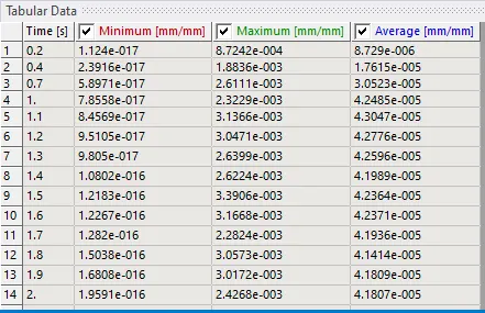
CASE 2
_ _ _ _ _ _ _ _ _ _ _ _ _ _ _ _ _ _ _ _ _ _ _ _ _ _ _ _ _ _ _ _ _ _ _ _ _ _ _ _ _ _ _ _ _ _ _ _ _ _ _ _ __ _ _ _ _ _ _ _ _ _ _ _ _ _ _ _ _
Deformation Contours:
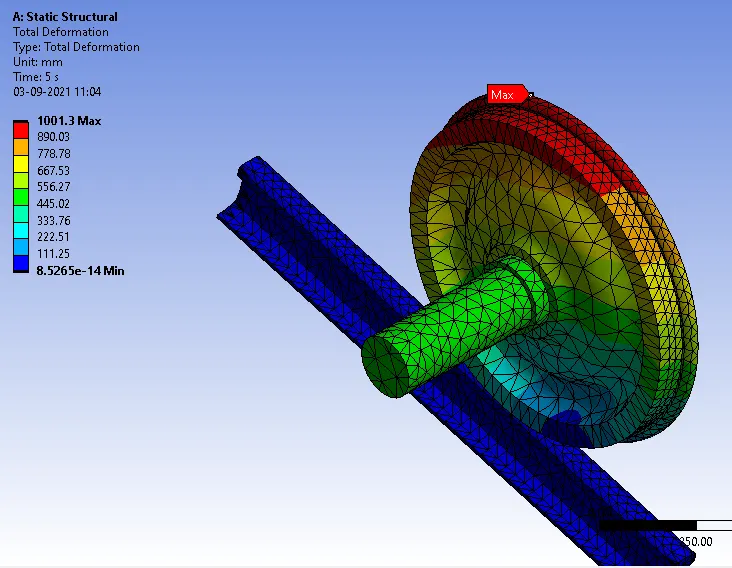
CASE 1
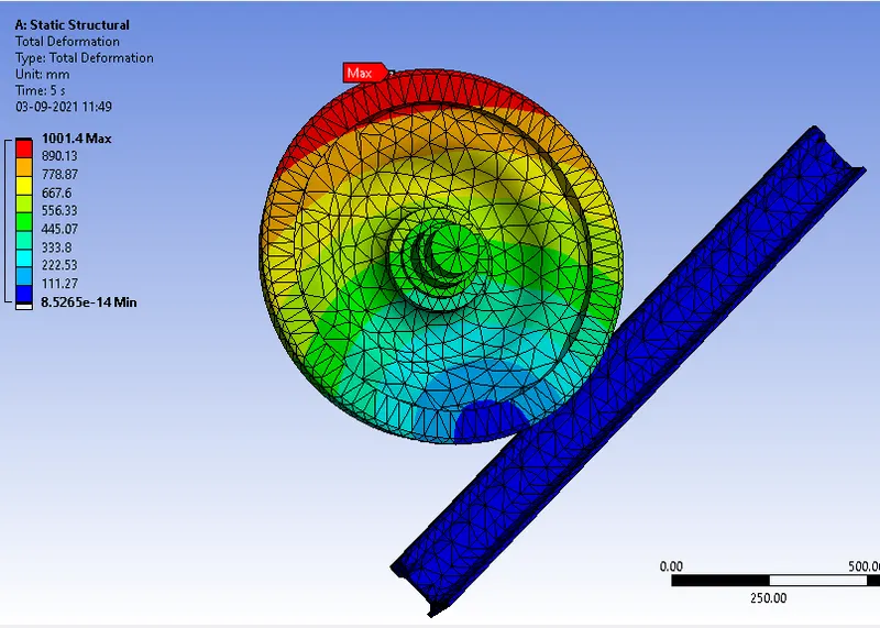
CASE 2
Deformation Plots:
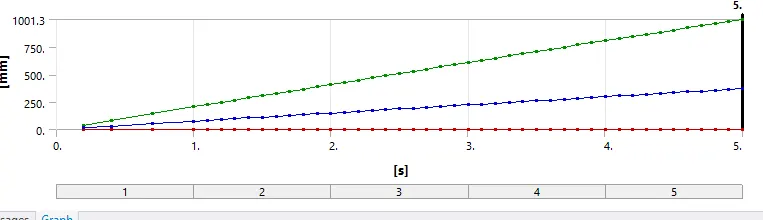
CASE 1
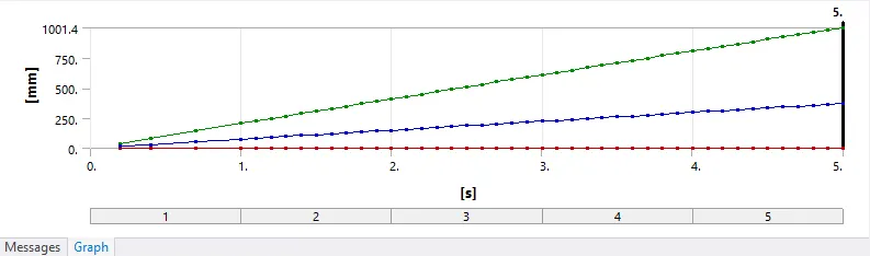
CASE 2
Deformation Data:
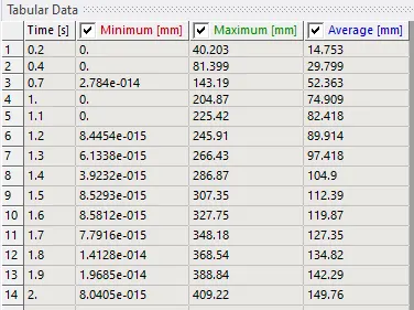
CASE 1
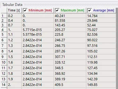
CASE 2
_ _ _ _ _ _ _ _ _ _ _ _ _ _ _ _ _ _ _ _ _ _ _ _ _ _ _ _ _ _ _ _ _ _ _ _ _ _ _ _ _ _ _ _ _ _ _ _ _ _ _ _ __ _ _ _ _ _ _ _ _ _ _ _ _ _ _ _ _
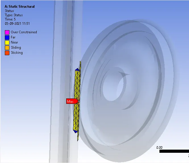
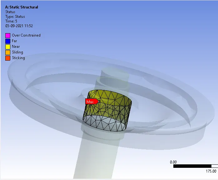
Contact Status:
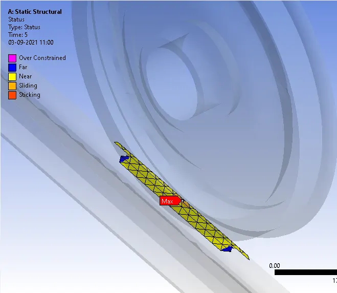
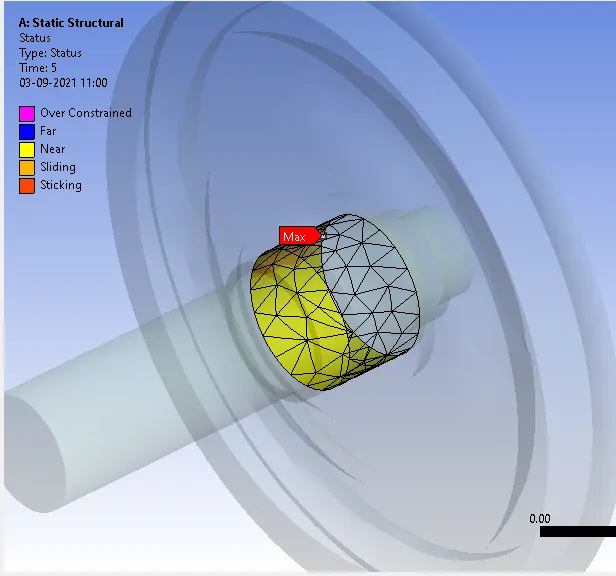
CASE 1
CASE 2
_ _ _ _ _ _ _ _ _ _ _ _ _ _ _ _ _ _ _ _ _ _ _ _ _ _ _ _ _ _ _ _ _ _ _ _ _ _ _ _ _ _ _ _ _ _ _ _ _ _ _ _ __ _ _ _ _ _ _ _ _ _ _ _ _ _ _ _ _
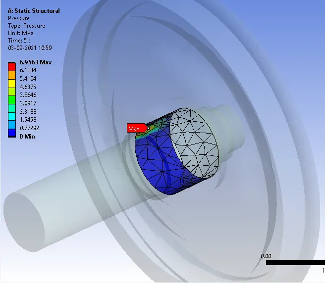
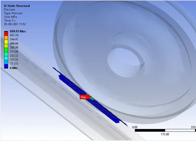
Pressure:
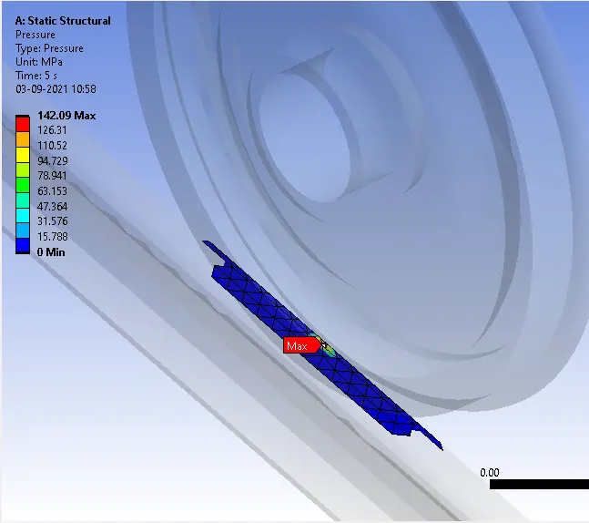
CASE 1
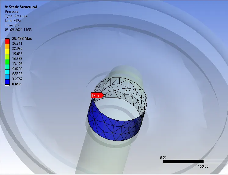
CASE 2
_ _ _ _ _ _ _ _ _ _ _ _ _ _ _ _ _ _ _ _ _ _ _ _ _ _ _ _ _ _ _ _ _ _ _ _ _ _ _ _ _ _ _ _ _ _ _ _ _ _ _ _ __ _ _ _ _ _ _ _ _ _ _ _ _ _ _ _ _ _
Fatigue Life:
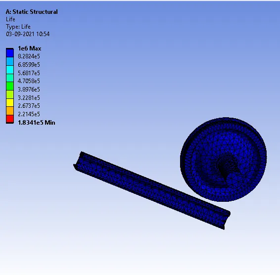
CASE 1
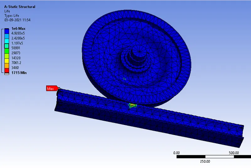
CASE 2
_ _ _ _ _ _ _ _ _ _ _ _ _ _ _ _ _ _ _ _ _ _ _ _ _ _ _ _ _ _ _ _ _ _ _ _ _ _ _ _ _ _ _ _ _ _ _ _ _ _ _ _ __ _ _ _ _ _ _ _ _ _ _ _ _ _ _ _ _ _
User Defined Result:
- In many situations, we have seen customers ask for ways to output custom results from Ansys Mechanical. The usual results like Total Deformation, Equivalent Stress or Equivalent Plastic Strain may not be enough for our needs. Depending on the requirements, we can create User Defined Results to output the needed result.
- There are various output quantities given in the Worksheet of Ansys Mechanical.
Somehow, any results not output automatically, than we can write expression for that result and get needed results.
- If we want Total Deformation results, then we can use algebraic equation for Resultant Deformation in the form of vector quantities.
Here we want to find out the Total Deformation as a User Defined Result and want to check if it is similar to inbuilt result.
So, symbol for the Deformation used is U.

So, for expression we can write it in the form as given below:

UDF results for both cases are as given below:
CASE 1
CASE 2
_________________________________________________________________________________________________________
Conclusion:
- From the observations of comparative results, we can see high amount of increase in Stress and Strain.
- User Defined results are same as inbuilt results and near same in both cases.
- From the contact status we can observe little change in track and little sticking due to higher pressure in case of 500000 N loading. So it can be dangerous and leads to Derailment and power transmission loss.
- We know that Tensile Yield Strength of Structural Steel is 250 Mpa. So in case of 500000 N loads, Stress is going beyond the limit up to 467.85 Mpa. So there will be plastic deformation or permanent deformation can happen.
- As per results, we can see that fatigue life in 100000 loads is minimum 1.83 E5 cycles and for 500000 loads it is only 1715 cycles.
- So we should avoid higher loads for safety purpose.