Week 3 Verification of Weld Joints
OBJECTIVE:
To simulate three different types of welding using three different weld materials.
Case 1 : Stainless Steel: In this case, the material of the plates must also be the same. Use Stainless steel for both weldments and plates.
Case 2 : Aluminium Alloy: The material to be chosen for this case is Aluminum alloy(high strength, wrought). [Plate material to be used is
stainless steel]
Case 3 : Bronze: In order to simulate "Brazing", you should be using bronze as the weld material. Assign Stainless Steel to both plates and
Copper to the "Ribs".
PROCEDURE:
Open the static structural analysis system in the Project schematic. Rename it to weld_joints. The material used for analysis are stainless
steel, aluminum alloy, bronze and copper.. These materials are added to the material library in Engineering Data. Now proceed to import the
Geometry. Import the Geometry and verify the geometry proper and update and open the Mechanical module.
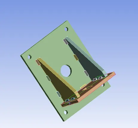
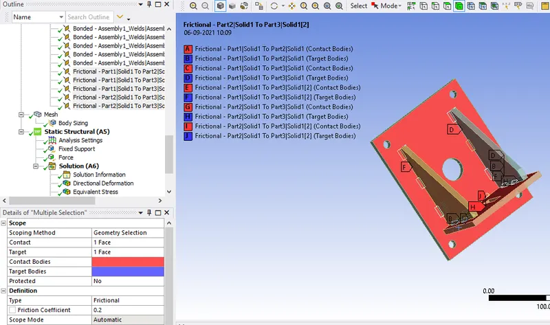
The Ansys automatic contact detection has detected some initial contact between the plates and the ribs and also the it has detected the weld
joints. The type of contact for weld connections is Bonded, which is fine. But the plates and ribs are connected to each other through the spot
weld. For them, Frictional type contact is used with coefficient of friction as 0.2.
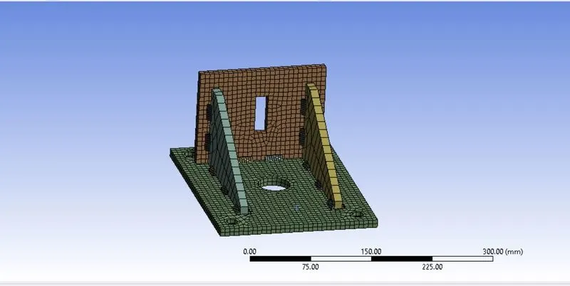
For meshing, sizing of 7 mm is used on the plates and the geometry is meshed.
In the analysis settings, larger deflection is turned on, so that we can capture any non linear behavior in the non linear region. Now apply the
boundary conditions. The bigger plate is to be mounted on the wall and fixed at all holes. Apply fix support at the holes of the bigger plate. Go to
Static structural > Insert > Fixed support and fix all the holes of the bigger plate and apply a force of 15000 N on the rectangular slot of the
smaller plate. Go to Static structural > Insert > Force > By Components. Enter Y componenet as 15000 N .
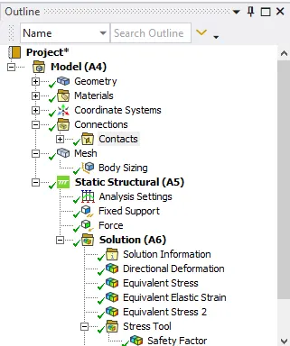
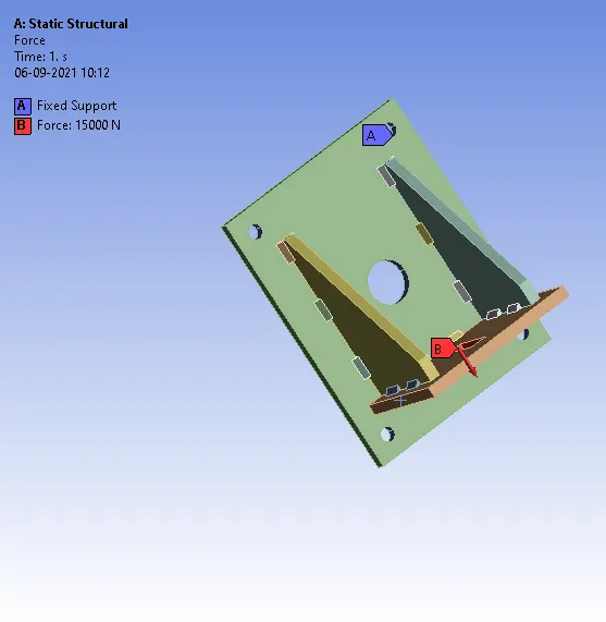
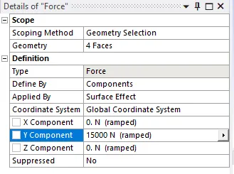
All the boundary conditions are defined and the solution for equivalent stress, deformation in the Y direction, strain in the ribs and the stress
in the spot weld are obtained.
Results:
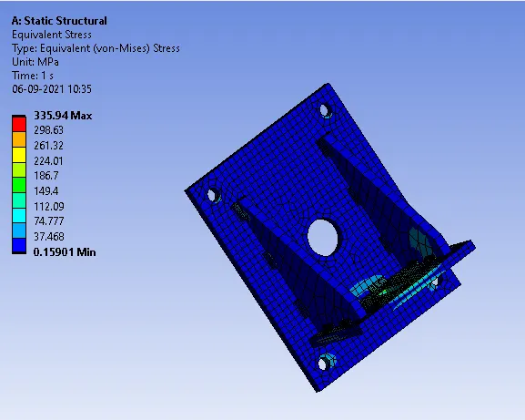
Case 1: In this case, Stainless steel for both weldments and plates is used.
Stress contour:
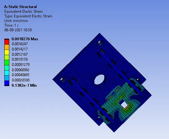
Strain contour:
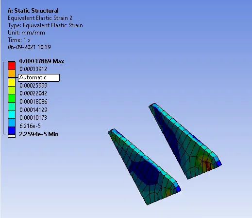
Strain in the Ribs:
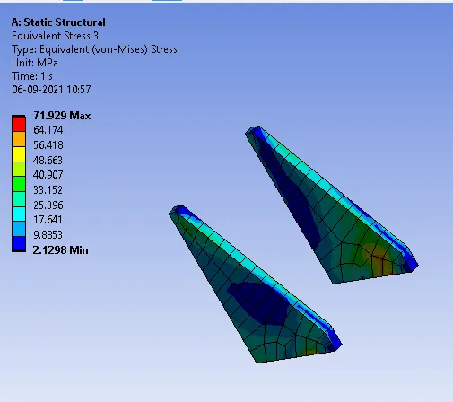
Stress in ribs:
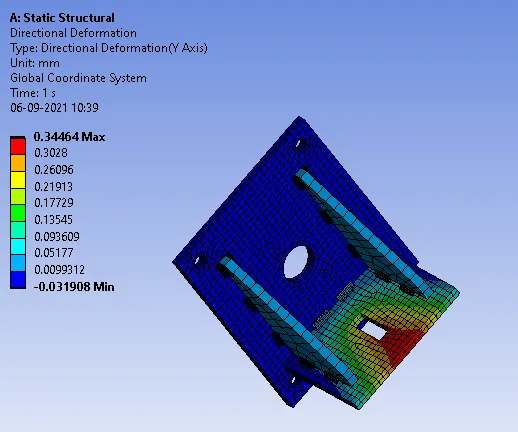
Deformation:
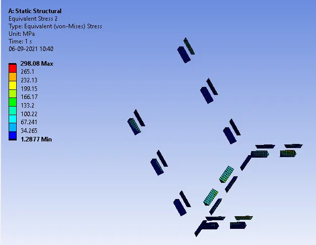
Stress in the weld joints:
Safety Factor:
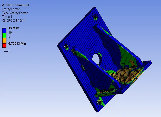
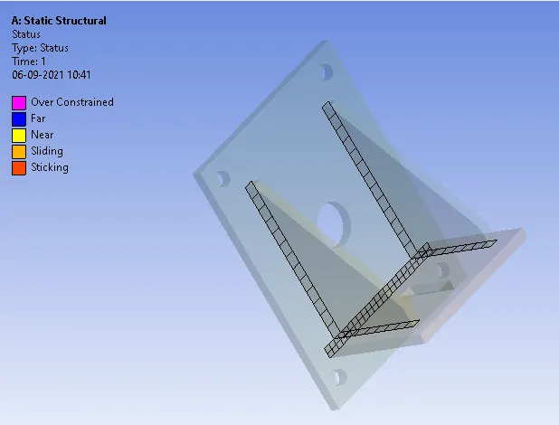
Contact Status:
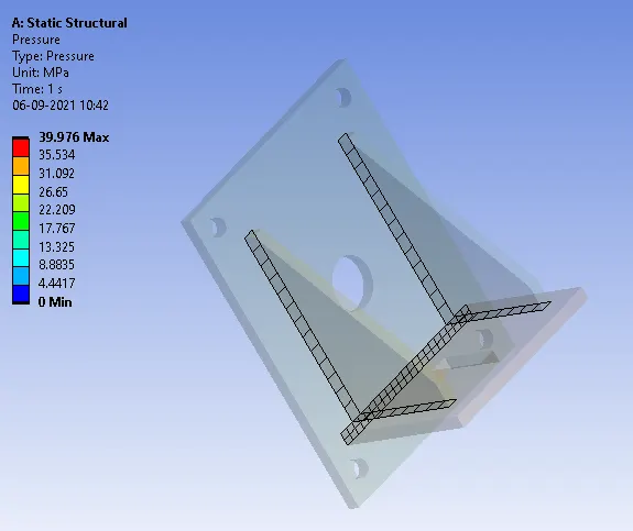
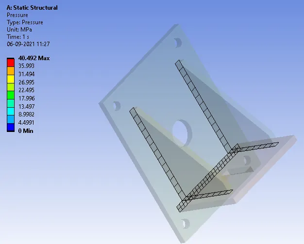
Contact Pressure:
Case 2: The material to be chosen for this case is Aluminum alloy(high strength, wrought). Plate material to be used is stainless steel.
Stress contour:
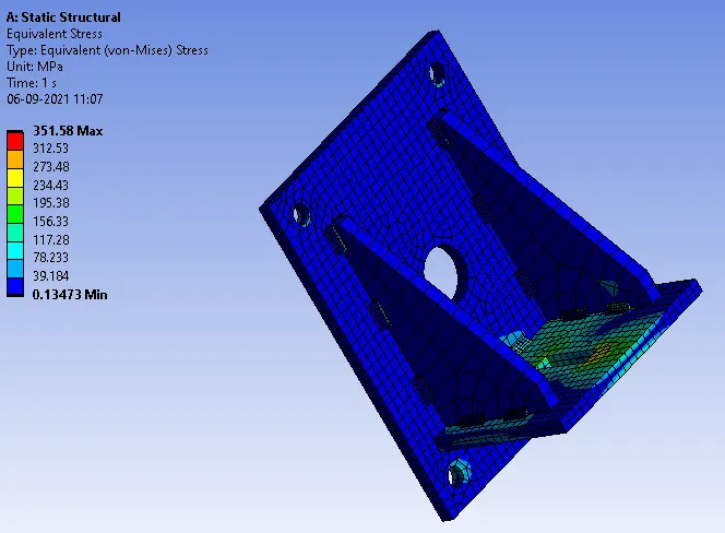
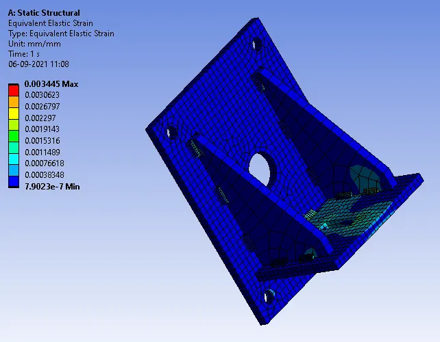
Strain Contour:
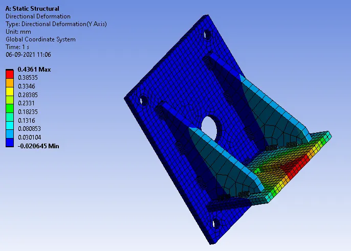
Deformation:
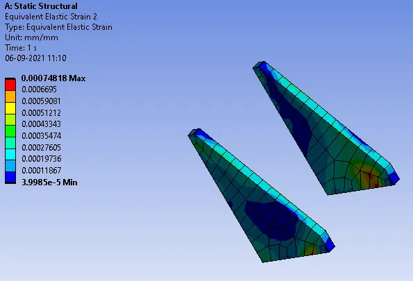
Strain in the Ribs:
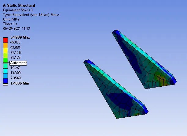
Stress in ribs:
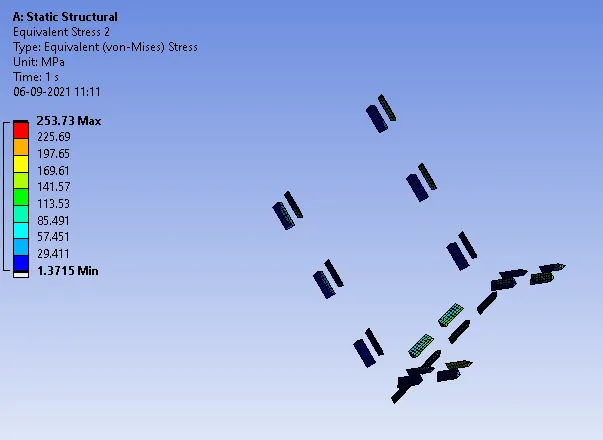
Stress in the weld joints:
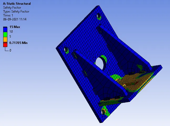
Safety Factor:
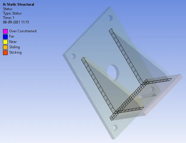
Contact Status:
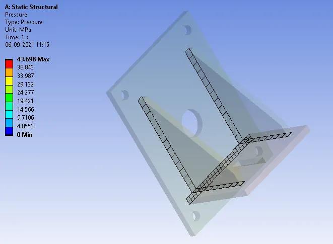
Contact Pressure:
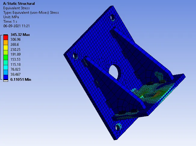
Case 3: Bronze:Using bronze as the weld material, assign Stainless Steel to both plates and Copper to the "Ribs".
Stress contour:
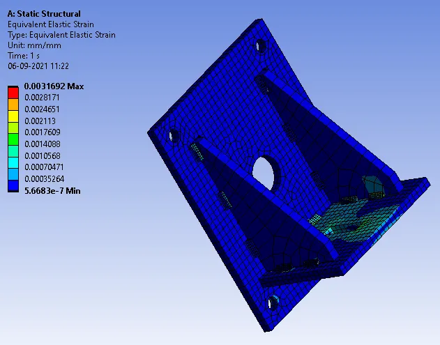
Strain Contour:
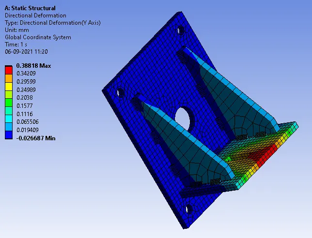
Deformation:
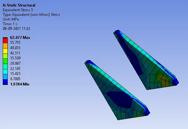
Stress in the ribs:
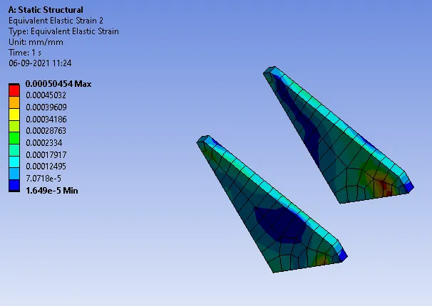
Strain in the ribs:
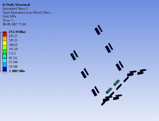
Stress in the weld joints:
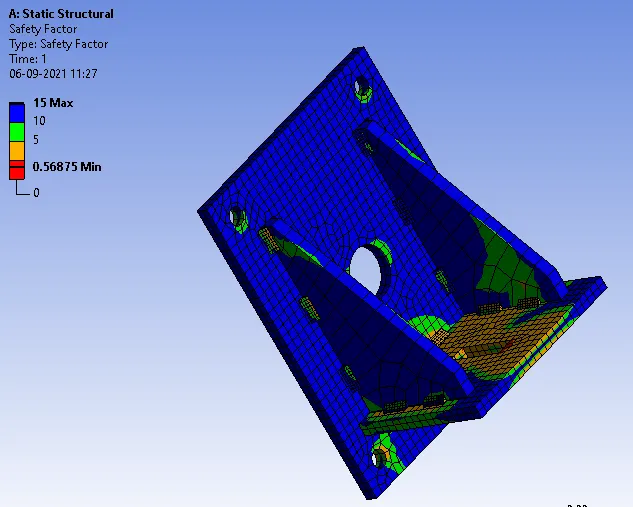
Safety Factor:
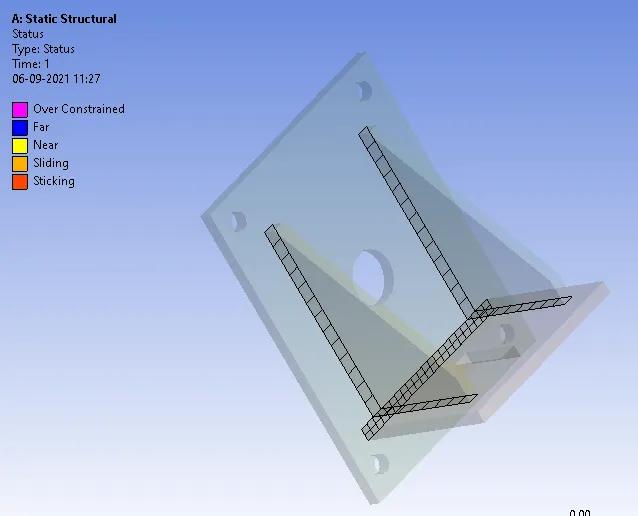
Contact Status:
Contact Pressure:
| CASE NO | STRESS CONTOUR | STRAIN CONTOUR | DEFORMATION | STRESS IN RIBS |
STRAIN IN RIBS |
STRESS IN WELD JOINTS |
| CASE 1 |
MAX: 335.94 MIN: 0.15901 |
MAX:0.0018276 MIN:9.1382E-7 |
MAX: 0.34464 MIN: -0.031908 |
MAX: 71.929 MIN: 2.1298 |
MAX:0.00037869 MIN: 2.25E-5 |
MAX: 298.08 MIN: 1.2877 |
| CASE 2 |
MAX:351.58 MIN:0.13473 |
MAX:0.003445 MIN:7.9023E-7 |
MAX:0.4361 MIN:-0.020645 |
MAX:54.989 MIN:1.4006 |
MAX:0.00074818 MIN:3.9985E-5 |
MAX:253.73 MIN:1.3715 |
| CASE 3 |
MAX:345.32 MIN:0.11051 |
MAX:0.0031692 MIN:5.6683E-7 |
MAX:0.38818 MIN:-0.026687 |
MAX:62.477 MIN:1.9784 |
MAX:0.00050454 MIN:1.649e-5 |
MAX:253.19 MIN:1.3881 |
As seen above, max stress and deformation is observed in the plate with Stainless steel as material and Bronze as material for weld
connection. Highest stress in the weld connection is observed in the weld connection with stainless steel material. For all the cases, higest stress in
the weld conection is observed at the same location, i.e, weld connection near the free end of the plate as observed in the stress contour.
CONCLUSION:
Thus, given three different types of welding joints are simulated using three different weld materials and the location of max stress in the weld
connection is identified.