Week 3 Sheet metal Bending challenge
Objective:
The aim of the challenge is to perform the simulation for the sheet metal bending operation, using aluminium alloy, copper alloy and magnesium alloy. Also for the aluminimum alloy sheet, frictional coefficient and mesh sizes were changed to see the difference in the results.
Case setup and execution:
First the "Static structural" module was opened in Ansys Workbench.
The engineering data was opened to add materials to the library. From general non-linear materials, aluminium alloy, copper alloy and magnesium alloy were added. The density and tangent modulus of aluminium alloy were modified as per the video lecture and it was named aluminium alloy NL 1199.
Then the geometrical model was imported. Then the "model" was opened in the "Ansys Mechanical". The die and punch were assigned the structural steel material and the sheet metal was assigned aluminium alloy NL 1199. The material of sheet metal was parameterised.
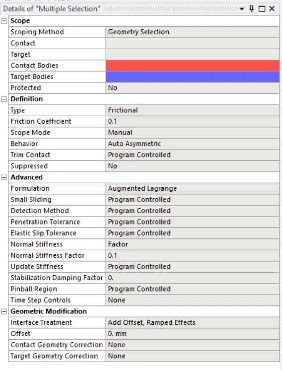
Then the contacts were defined by selecting the faces of the punch and the surface of the sheet as well as the sheet surface anf the faces of the die. The contacts were made "frictional", the behaviour was "Auto asymmetric", the "Augmented Lagrange" formulation was used, normal stiffness factor of 0.1 was used and the for the interface "Add offset, ramped effects" option was used. The coefficient of friction was given as 0.1 and it was parameterised.
Then the punch abd die were meshed using the element size of 4 mm. The sheet was provided the mesh size of 1 mm. Then mesh sizing option was used to get 1 mm mesh size on the faces of the die and punch. Then mesh method was used to give tetrahedron mesh to the sheet metal.
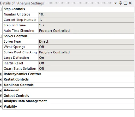
In the analysis settings, the number of load steps was chosen as 10. The auto stepping was kept program controlled for all the load steps. The step end time was 1 sec. The "large deflection" option was turned on.
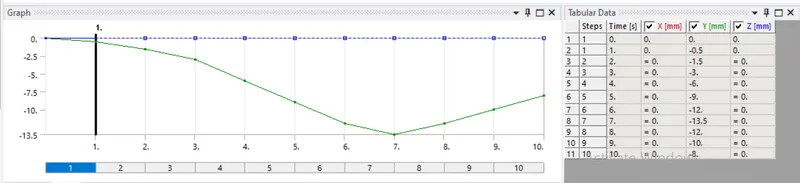
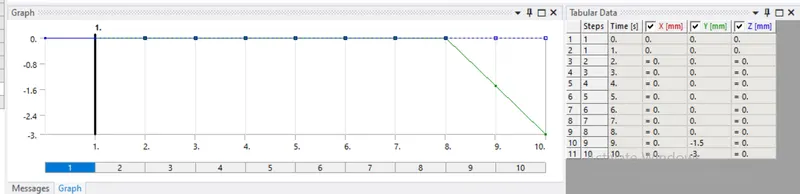
Then by right clicking on "analysis settings", "displacemnt" was inserted. The faces of the punch were selected and given displacement values in tabular form as shown in image below:
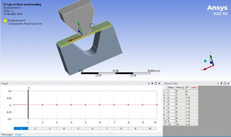
Another displacement was inserted for the sheet metal. This was restrict its motion in local z-direction as shown below:
The die was also provided the displacement in tabular form as shown below to separate it from the sheet metal after the bending operation is done.
The the "Solution" tab was right clicked to insert the desired outputs of Y-directional deformation, equivalent elastic strain and equivalent von mises stress. Contact tools for 2 contacts were also inserted to check contact pressure and frictional stress along the contacts. The force reaction was aslo requested as the output. The maximum, minimum and average values of these properties were also parameterised.
Results:
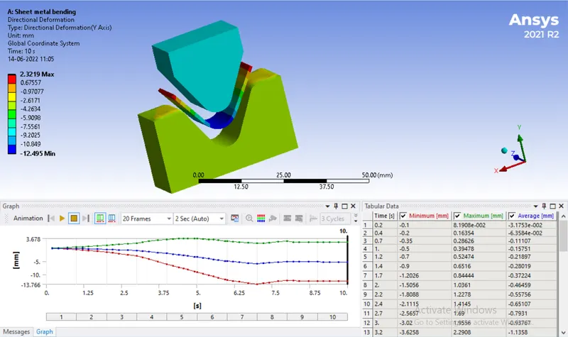
The following results are shown for aluminium alloy NL 1199 material and the frictional coefficient of 0.1.
Directional deformation:
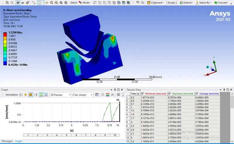
Equivalent elastic strain:
Equivalent stress:
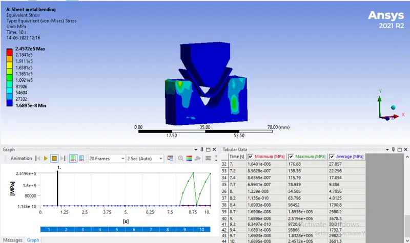
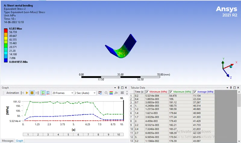
Equivalent von mises stress in the sheet:
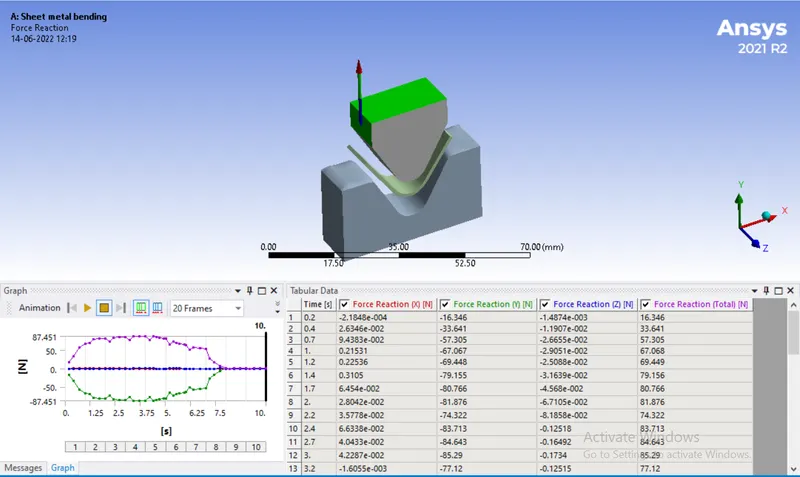
Force reaction:
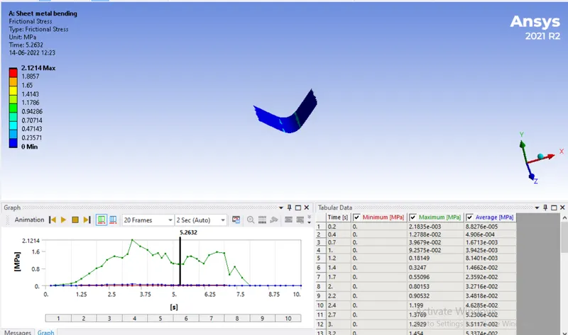
Contact frictional stress:
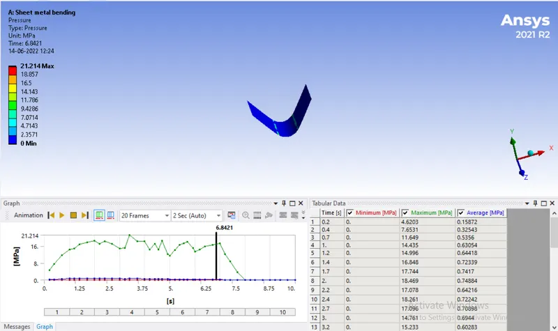
Contact pressure:
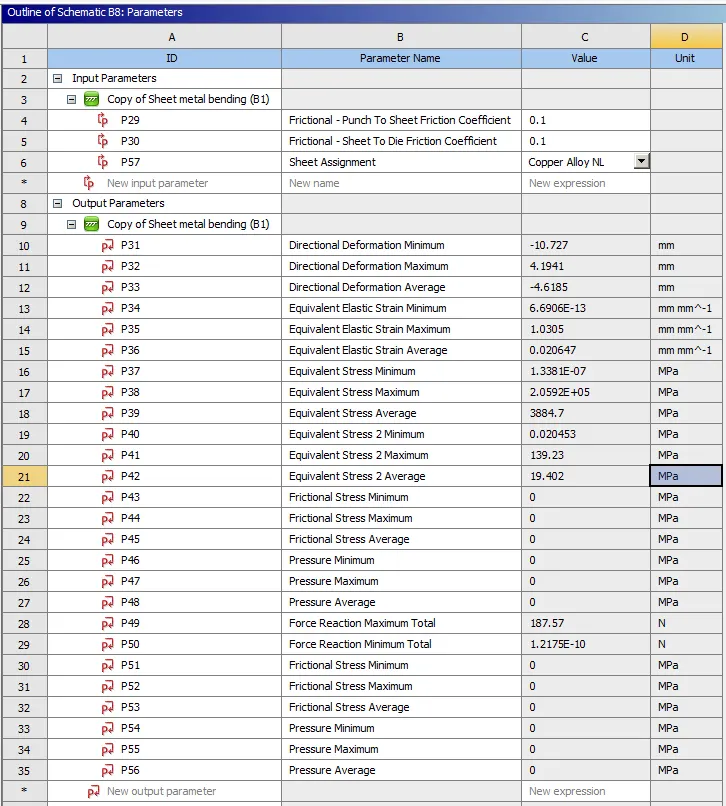
Since the material of the sheet metal was parameterised, the parametric study was done for copper alloy NL and magnesium alloy NL materials with the frictional coefficient of 0.1. The results in both the cases are shown below:
Copper alloy NL:
Magnesium alloy NL:
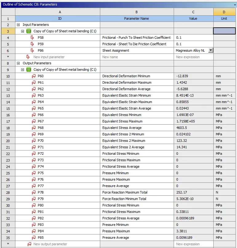
The following table summarises the results for the maximum values in case of the 3 materials:
| Materials | Aluminium alloy NL 1199 | Copper alloy NL | Magnesium alloy NL |
| Y-directional deformation (mm) | 2.3219 | 4.1941 | 1.4342 |
| Equivalent elastic strain (mm/mm) | 1.2298 | 1.0305 | 0.85855 |
| Equivalent stress (MPa) | 2.4572 e+05 | 2.0592 e+05 | 1.7158 e+05 |
Case 2:
With the material as Aluminium Alloy, the friction coefficient was changed to 0.19 and the analysis was run. The results are shown below:

Case 3:
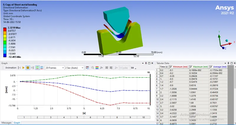
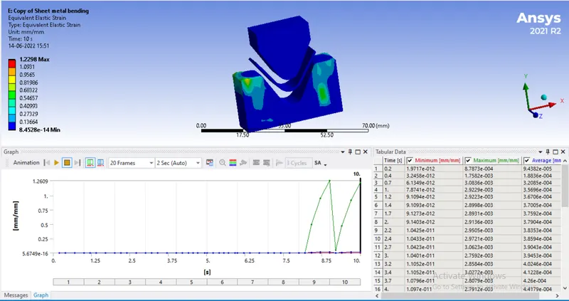
With Aluminium alloy as material, the mesh on the plate was refined. As there was no convergence for 0.5mm mesh size, 0.9 mm mesh size was used. The results are shown below:
Directional deformation
Equivalent elastic strain
Equivalent stress
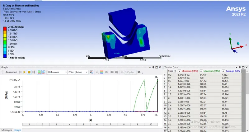
The following table shows comparison of results for mesh sizes:
| Mesh size | 1 mm | 0.9 mm |
| Y-directional deformation (mm) | 2.3219 | 2.3219 |
| Equivalent elastic strain (mm/mm) | 1.2298 | 1.2298 |
| Equivalent stress (MPa) | 2.4572 e+05 | 2.4572 e+05 |
Conclusion:
Thus it can be seen that the results are affected by the material properties, mainly the Young's modulus. Also the mesh size affects the result, although here it is not clear, as the mesh size is not very different. The zip file is attached with the report.