Week 3 - 2D meshing for sheet metal
Aim:
The aim of this challenge is to perform the 2D meshing of the given components after performing the geometry cleanup and extracting the midsurface. THe elements are supposed to meet the mentioned quality criteria.
Procedure:
1. The given model was opened in ANSA using File-open command.
2. The geometry check was performed to find out any geometrical errors. No geometrical errors were found in the model.
3. Then from the Properties tab, out of the total 5 properties, each one was turned on and off to work on each component one by one.
4. The midsurface was extracted using auto midsurface technique. Under the TOPO tab, Faces-midsurface-skin option was used.Under the options window, Delete original faces option was deselected. The selection option was chosen as PID region and the distance to offset was given as half of the thickness.
The auto midsurface option was used because the components had constant thickness. Also it captures the geometrical features more accurately and in lesser time. The constant thickness can be seen in images below, taken at different locations:
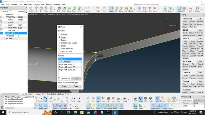
- After the midsurfaces were extracted, their orientation was checked.
- In the outer component of the hood, to capture the hemming region such that the elements satisfy the quality criteria, some of the edges were toggled using Macros-join option in Mesh tab. Only the edge at the peak of the bend was retained.
- In all the components the macros were joined such that they form rectangles as far as possible. Then the length of the perimeter and the macros was given as 5 mm using perimeter-length option.
- Then each of these macros was meshed. First the macros with difficult shapes were meshed, then the simple macros were meshed.
- To remove the tria elements, Reconstruct command was used. Also the number of elements on the perimeter or the edges of the macros were also changed to remove trias. In some case, split and join option was used to cnvert tria elements into quad elements.
- Smooth option was also used to smoothen the mesh.
- In the inner component, the geometry was very difficult. But the component was also symmetrical. Hence the midsurface was first cut using Faces-project cut option in TOPO tab. The only macro which was not symmetrical was excluded. The half of the midsurface was deleted using Delete-entities option.
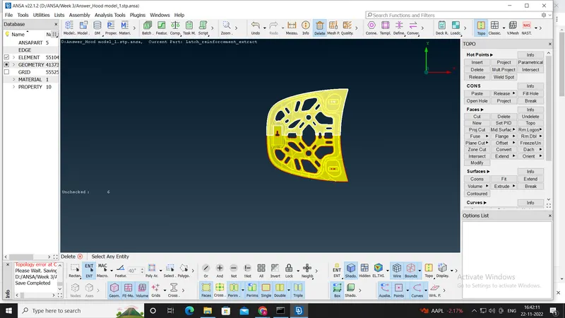
- After meshing half of the midsurface, it was reflected using Transform-copy-entities-symmetry-default symmetry plane option.
- After reflect option, the entities had to be connected. From TOPO tab, Faces-Topo option was used to connect the unconnected faces.
- After the entire meshing was done, there were 4 unmeshed elements in the inner component of the hood. There was a tiny gap between the edge of the element and the edge of the geometry. To rectify this, first the "Fine" option was used. This yielded a small surface between the element edge and the geometry edge. Then from TOPO tab, Faces-delete option was used to delete these tiny faces. This removed the unmeshed areas.
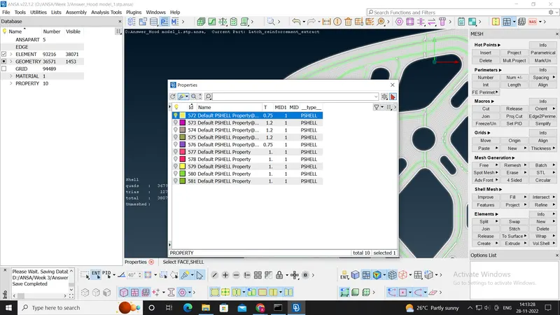
- For the thickness, the desired thickness was assigned at the time of creating the midsurface itself as shown in the following image:
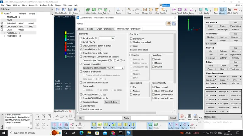
17. The element quality criteria tab was opened using F11 key. Under the "Presentation parameters" tab, the "Draw shell as solid" option was ticked to enable the same as shown below:
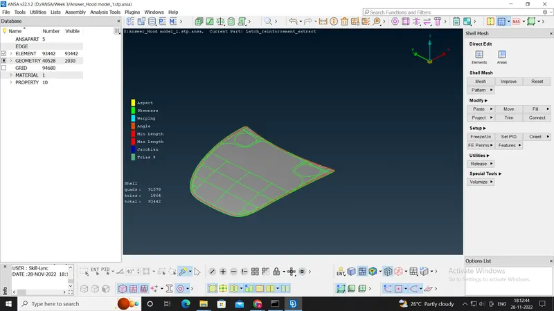
18. The following image shows that there are no off elements in the model:
Learning Outcomes:
Learned how to 2D mesh as well as mesh modification using reconstruct, smooth, Num+/- , split and join commands. Learned how to use reflect option to
Conclusion
Thus the model was meshed successfully. Please find the model attached to the report.