Assignment 1-2D Meshing Challenge
Objective:
The objective of the challenge is to get the understanding of the 2d meshing practices in Hypermesh, including the geometry cleanup of the CAD model, the cleanup of midsurface geometry and ensuring the prescribed criteria for the element size. The challenge required working on 3 geometries provided in the question.
Explanation:
Part-1:
The .hm file of part-1 was first opened using Atair Hyperworks. Then the view was changed to Wireframe geometry. The "quick edit" tab was opened to check and correct the geometry of the CAD model. The image of the same is below:
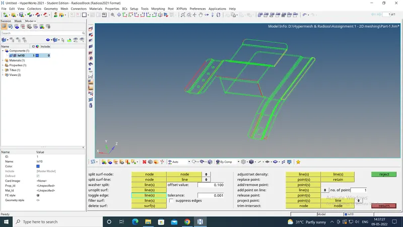
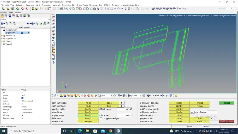
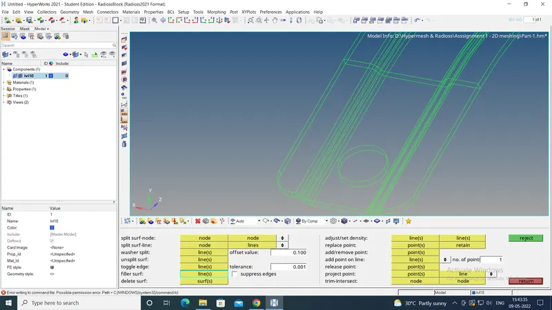
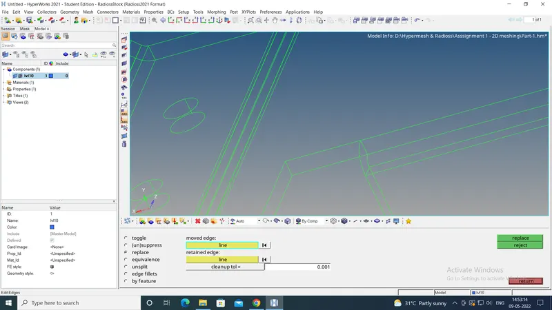
The model had free edges denoted by red colour as well as edges connecting more than 2 surfaces, denoted by yellow colour. To remove the red edges, the "toggle edge" option in "quick edit" tab was used to toggle the edges within the tolerance of 0.001. For the red edges which could not be toggled, "filler surface" option was used. For the edges remaining after this, the "replace line" option was used.
After using the toggle edge option:
After using the filler surface option:
After using replace line option:
To remove the yellow edges, "delete surface" option was used under the "delete" icon denoted by the red cross symbol. This deleted the extra surface and the edges again became green.
After using the "delete surface" option:
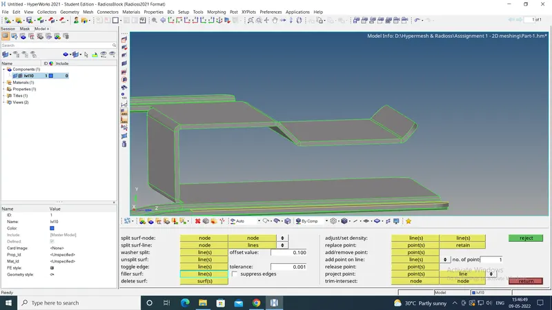
Also some points were displaced from their correct position. This was rectified by using the "repalce point" option in "quick edit".
After using the replace point option:
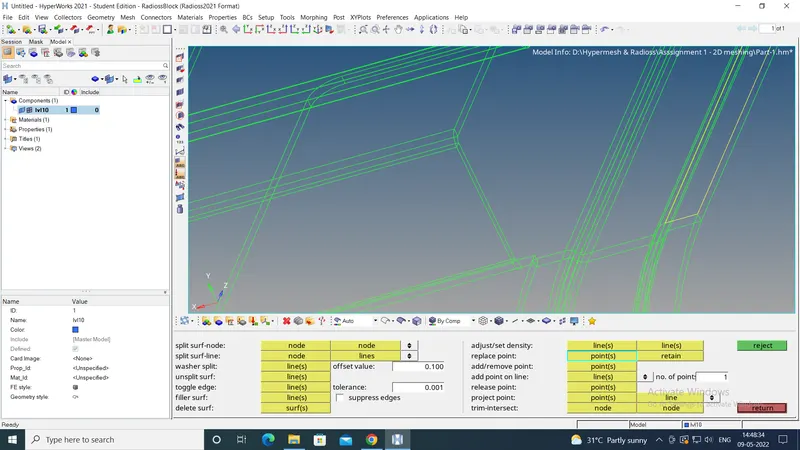
Also a surface extended beyond its correct boundaries. To rectify this, first the surface was trimmed using plane/surface in the "surface edit" option. Then the unwanted trimmed portion was deleted using "delete surface" option.
After the trim and surface delete:
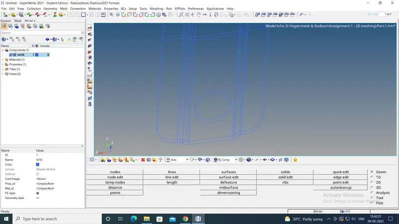
The final cleaned up CAD model geometry looked as follows:
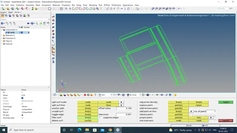
Then the "midsurface" option was used to extract the midsurface of the model. The image of the extracted midsurface is provided below:
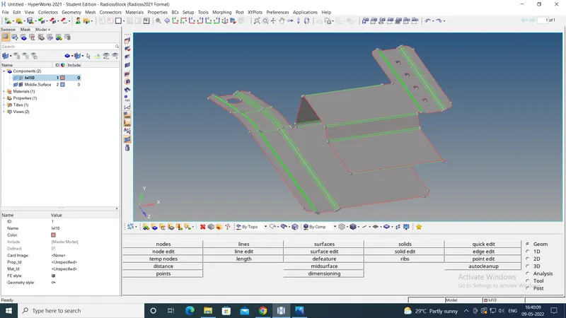
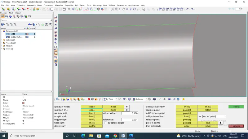
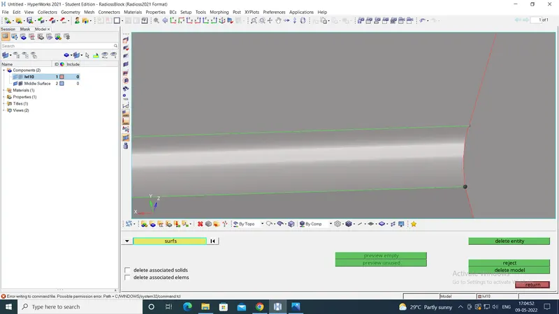
The midsurface also needed to be cleaned up. First of all, there was a small surface extending beyond the actual length. It was first split using "split node-to-line" option in "quick edit". Then the extra surface was deleted.
Before surface delete:
After the surface delete:
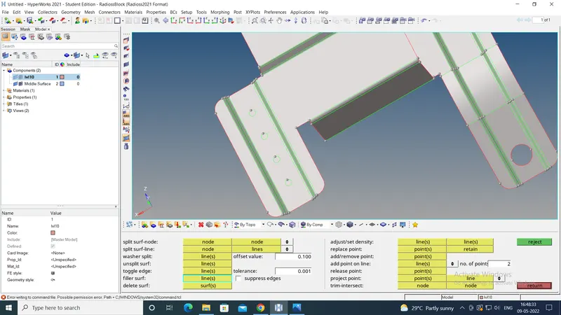
The holes with diameter less than 5mm were filled using "surface filler" option in "quick edit".
After the holes were filled:
The edges of the filled holes were toggled.
After the toggling of hole edges:
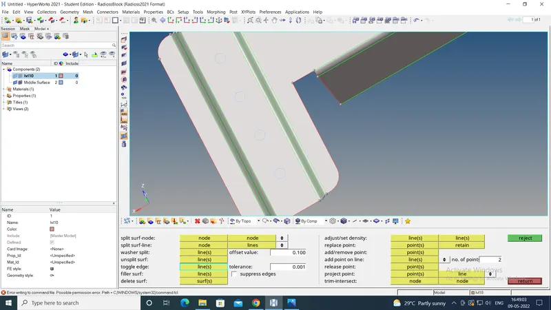
As the target element size was prescribed as 5mm the features like fillets with less than 5 mm size had to be modified. This was done by splitting the fillets by lines, created using "split node-to-line" option. In cases where the said option did not work, a "midline" was created by using midline option in "lines" tab. Then the surface was split using the midline. After this the edges of the fillet were toggled.
An example of the above operations is shown below:
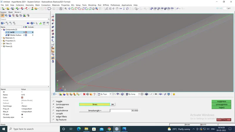
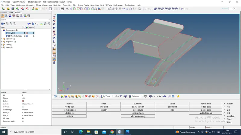
After all these oprations, a clean midsurface was obtained, which is shown below:
Before meshing, from the "Preferences" tab from the Menu bar, "Criteria file setting" option was opened, in which the element sizing criteria were input. Then under the "2D" tab, "automesh" option was used to mesh the surfaces one-by-one, to avoid failing of elements under the sizing criteria.
The "Element Colour mode" was set to "By element quality" to readily check the quality of the elements created. Then various operations were carried out to ensure the elements meet the sizing criteria.
The "node edit" option was used to move the nodes to adjust the element size. The "rebuild mesh" option was used to rebuild the mesh in selected area. The number of nodes were increased on decreased to adjust the mesh size.
Sometimes, in the "Element quality index" tab, "drag tria" and "optimise element" options were used to get desired mesh.
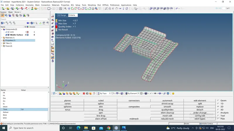
The final meshed midsurface is shown below:
Then in the "Properties" tab, the thickness of 3 mm was provided as shown below:
Part-2:
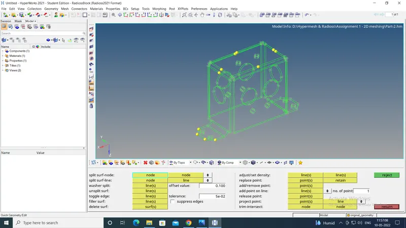
The given .hm file was opened in Hyperworks. As can be seen from image below, no geometry cleanup for the CAD model was needed.
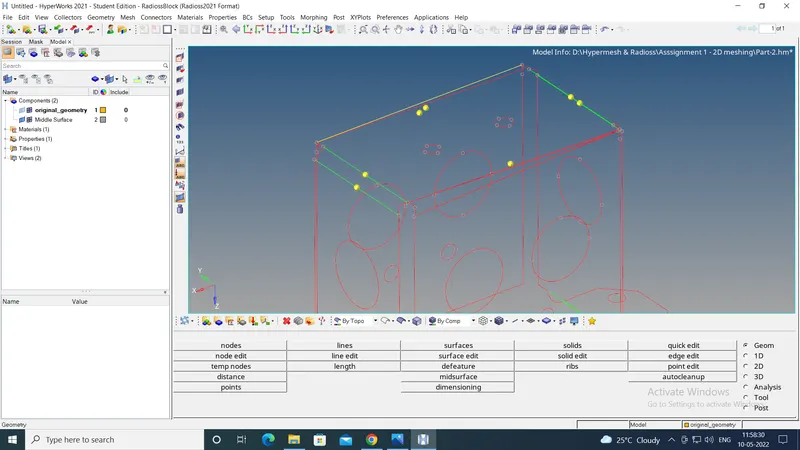
Then the midsurface was extracted using auto-extraction option. This midsurface had many errors, as shown below:
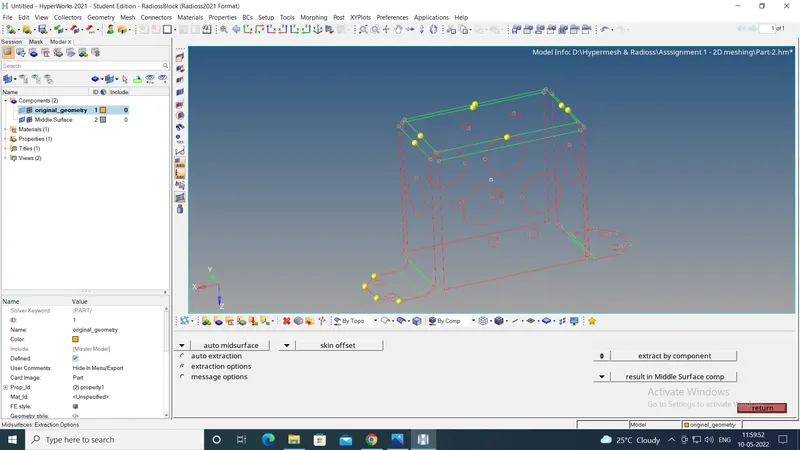
Hence under midsurface option, "Skin offset" option was used to extract the mid-surface. This extracted a clean midsurface as shown below:
Before meshing, from the "Preferences" tab from the Menu bar, "Criteria file setting" option was opened, in which the element sizing criteria were input. Then under the "2D" tab, "automesh" option was used to mesh the surfaces one-by-one, to avoid failing of elements under the sizing criteria.
Due to the geometric symmetry in the model, the appropriate surfaces were split using node-to-line option. Then only the split surfaces were meshed first and then the mesh was reflected.
The "Element Colour mode" was set to "By element quality" to readily check the quality of the elements created. Then various operations were carried out to ensure the elements meet the sizing criteria.
The "node edit" option was used to move the nodes to adjust the element size. The "rebuild mesh" option was used to rebuild the mesh in selected area. The number of nodes were increased on decreased to adjust the mesh size.
Sometimes, in the "Element quality index" tab, "drag tria" and "optimise element" options were used to get desired mesh.
The mesh of split surface:
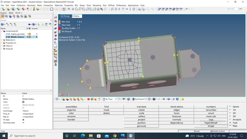
To reflect the mesh, under "Tool", "reflect" option was used. The plane to reflect across was selected by choosing the 3 nodes and a base point was chosen. "Keep connectivity" option was selected to maintain the connectivity of the elements after the reflect operation.
The mesh before reflection is shown below:
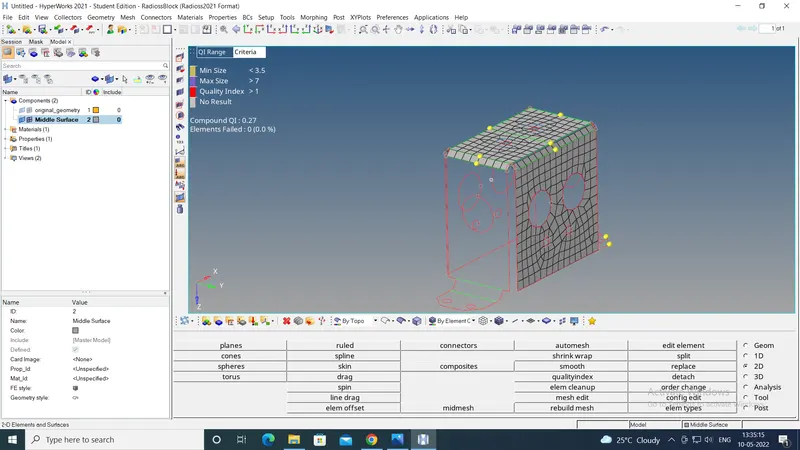
The final meshed midsurface after reflect operation is shown below:
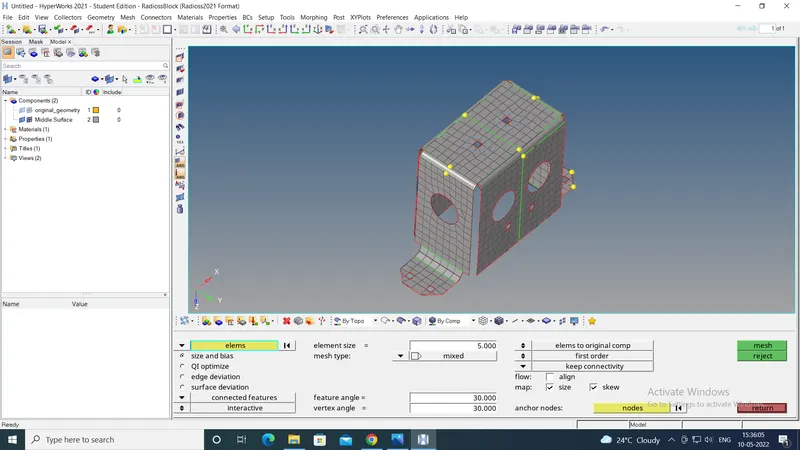
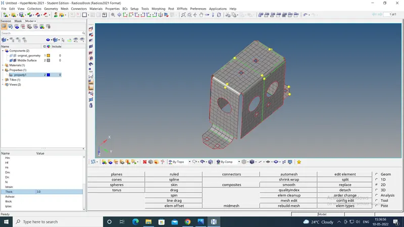
Then in the "Properties" tab, the thickness of 3 mm was provided as shown below:
Part-3:
The given .hm file was opened in Hyperworks. As can be seen from image below, no geometry cleanup for the CAD model was needed.
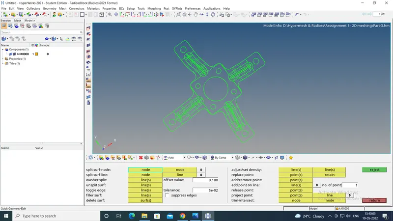
Then the midsurface was extracted using auto-extraction option.
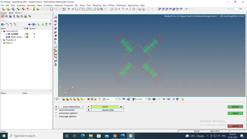
As the target element size was prescribed as 5mm the features like fillets with less than 5 mm size had to be modified. This was done by splitting the fillets by lines, created using "split node-to-line" option. In cases where the said option did not work, a "midline" was created by using midline option in "lines" tab. Then the surface was split using the midline. After this the edges of the fillet were toggled.
The final cleaned up midsurface is shown below:
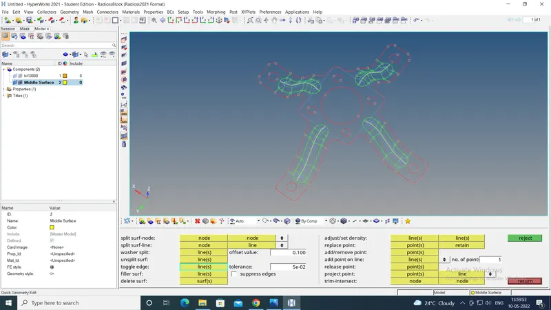
Before meshing, from the "Preferences" tab from the Menu bar, "Criteria file setting" option was opened, in which the element sizing criteria were input. Then under the "2D" tab, "automesh" option was used to mesh the surfaces one-by-one, to avoid failing of elements under the sizing criteria.
Due to the geometric symmetry in the model, the surfaces were split in quarter of the geometry. For this, under the "surface edit" tab, the "trim with surface" option was used. Two planes perpendicular to each other were created by specifying the normal to the plane (global axes) and a base point. Then only the split surfaces were meshed first and then the mesh was reflected.
The "Element Colour mode" was set to "By element quality" to readily check the quality of the elements created. Then various operations were carried out to ensure the elements meet the sizing criteria.
The "node edit" option was used to move the nodes to adjust the element size. The "rebuild mesh" option was used to rebuild the mesh in selected area. The number of nodes were increased on decreased to adjust the mesh size.
Sometimes, in the "Element quality index" tab, "drag tria" and "optimise element" options were used to get desired mesh.
The mesh of split surface:
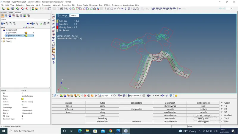
After 1st reflect operation:
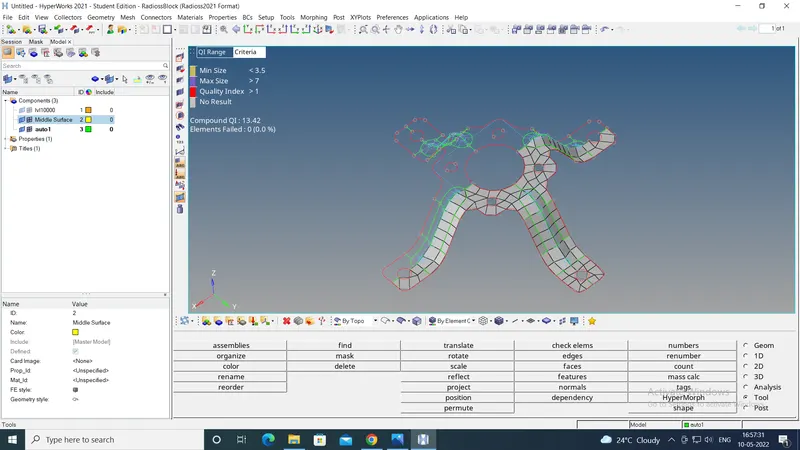
After 2nd reflect operation:
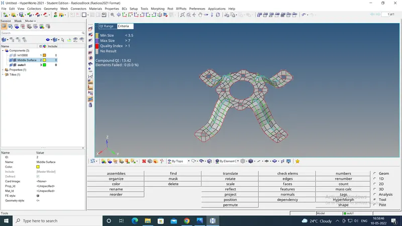
This time, to reflect, a direction in which the elements needed to be reflected was specified using the global axes. But the reflect operations created another body named "auto1" separate from the Midsurface. Hence under "Tool" organise option was used to move the elements to the midsurface and then the part "auto1" was deleted. Then under the "Properties" tab, a thickness of 3 mm was provided. The final mesh is as shown in image above.
Conclusion:
The challenge was a great learning opprtunity to get hands-on experience on the geometry cleanup operations. Also it helped learn the 2d meshing techniques. It helped understand the concepts of mesh flow, element quality and the reflect operation. Thus the challenge was a great learning experience in Hypermesh.