Week - 5 - Modelling Spotwelds
Aim: The aim of the challenge is to model a series of spotwelds using 2 different element types: in case 1 beam element is used and in case 2 solid element is used to model the spotweld.
Explanation: The simulation was run in both cases using following setup:
The unit system used is gm-mm-ms.
The sheet metal parts were given the shell section with MAT 001_Elastic as the material. The properties of steel were used for the material modelling.
One of the sheet metal parts was given a single point constraint (spc) by creating a set of nodes. The other sheet metal part was given a velocity of 3 mm/ms in the negative x-axis, using BOUNDARY PRESCRIBE_MOTION_SET keyword.
In control conditions, the hourglass check was given. The termination time was given as 4 ms.
The contact of the spotweld in both cases was modelled using CONTACT-SPOTWELD keyword. In this, the master parts were the two sheet metal parts and the spotweld was the slave part.
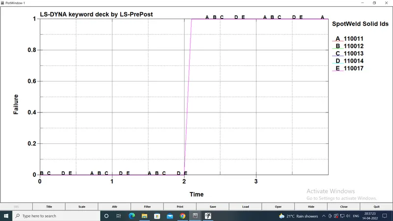
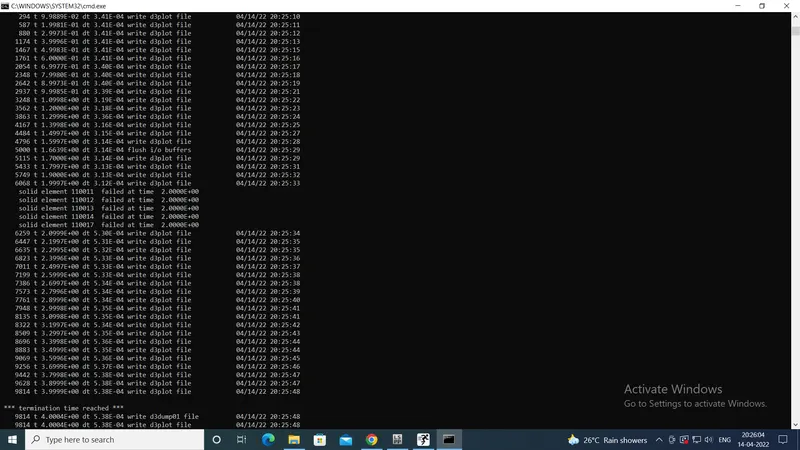
In both cases, the material for the spotweld was modelled using properties of steel. The failure time was given as 2 ms i.e. half the termination time.
In both the cases, the spotweld elements were created using ELEMENT EDIT option. All the elements were clubbed in a new part with PID 3.
Case 1: Spotweld modelled by beam elements
The spotwelds were modelled using beam elements. In the SECTION keyword, the beam section with the element formulation 16 was used.
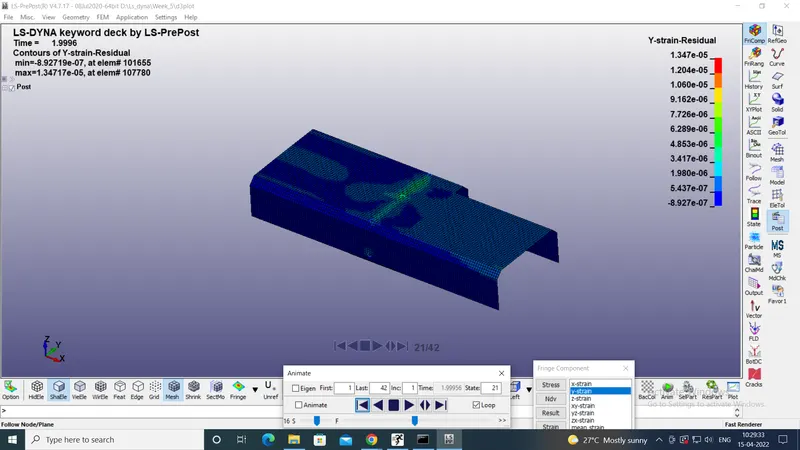
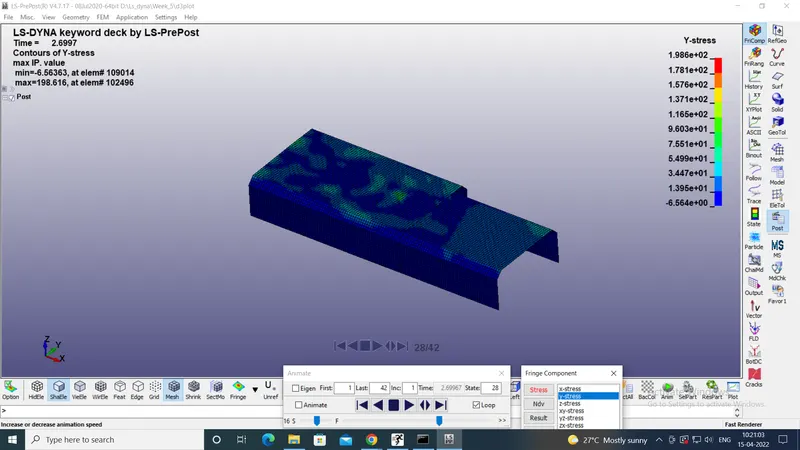
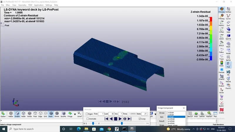
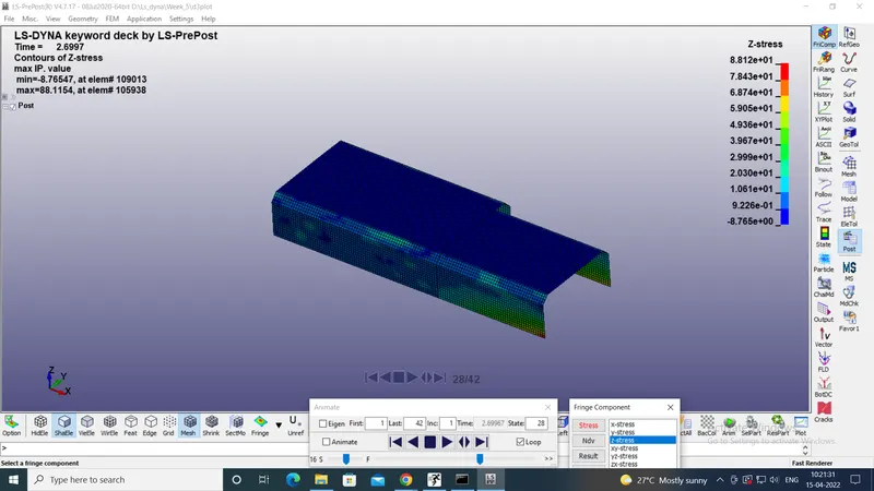
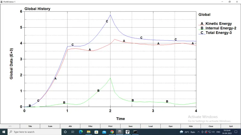
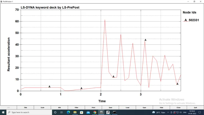
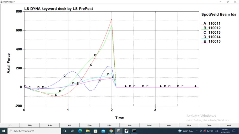
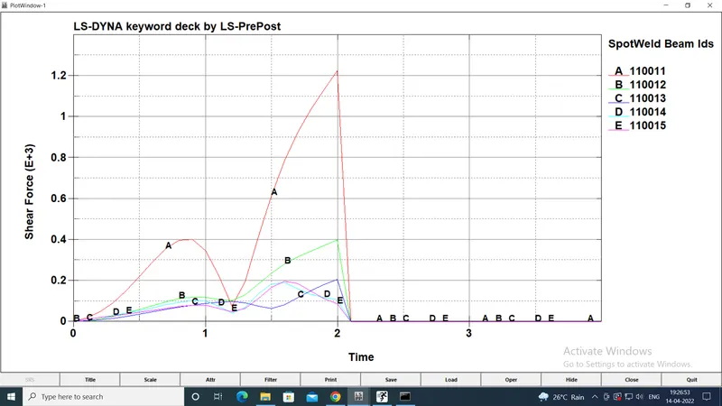
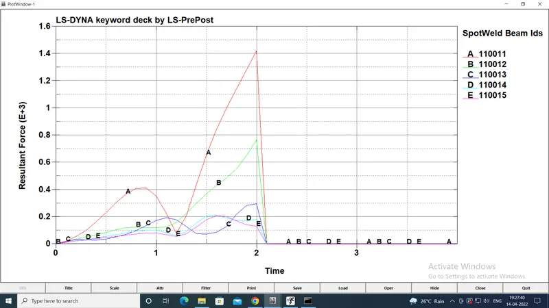
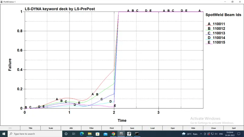
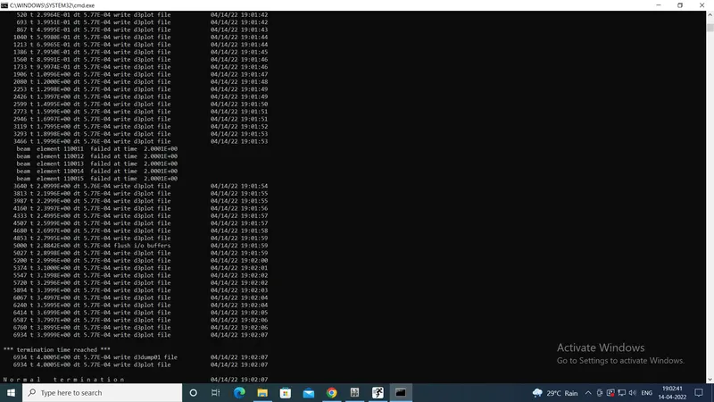
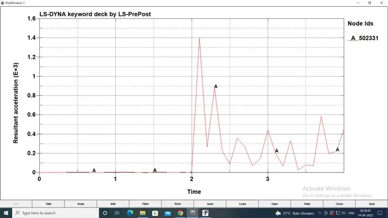
The results for the case 1 in terms of stresses, strains, energy, spotweld force etc. are given below:
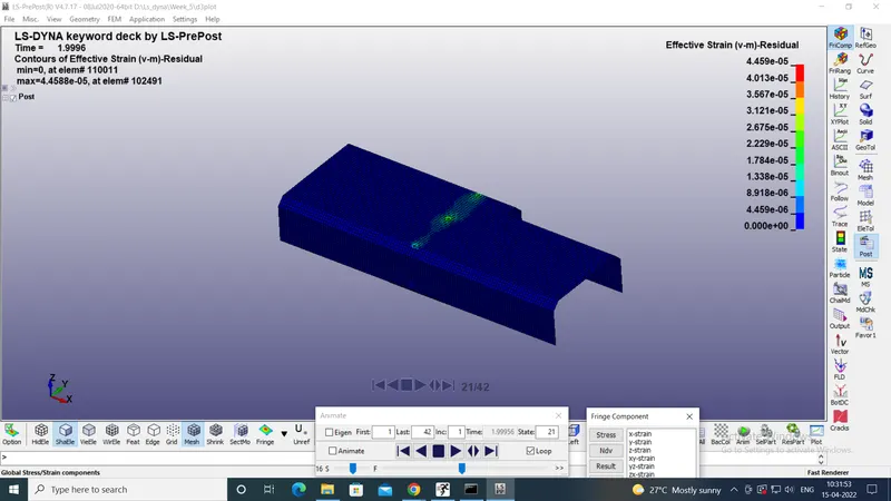
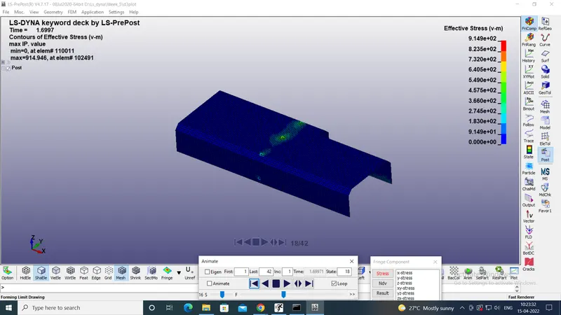
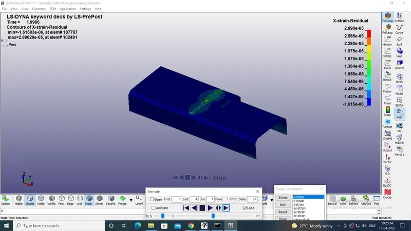
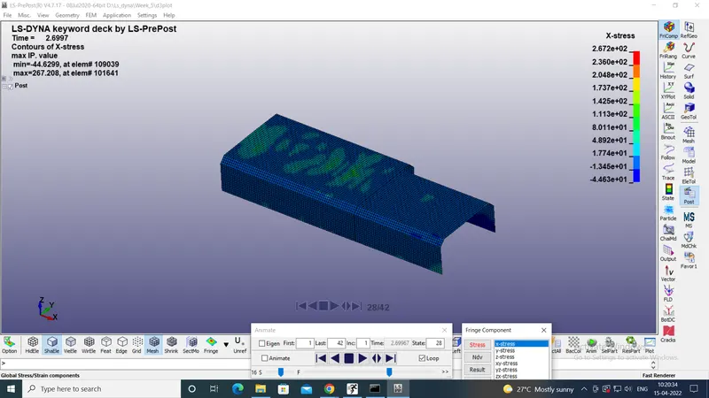
Case 2: Spotweld modelling using solid elements
In this case, the spotwelds were modelled using hexa solid element with the element formulation of 1.
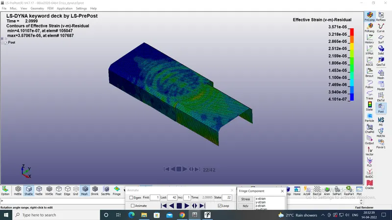
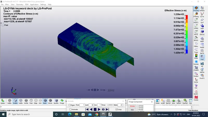
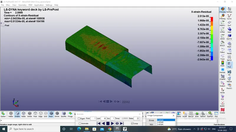
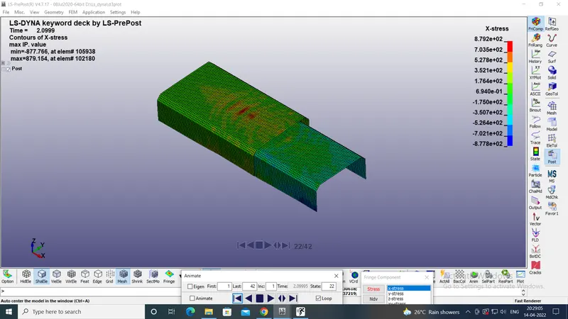
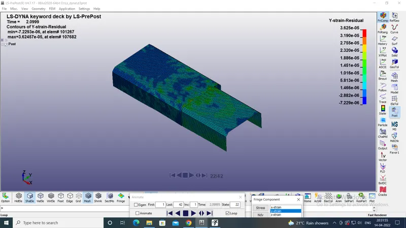
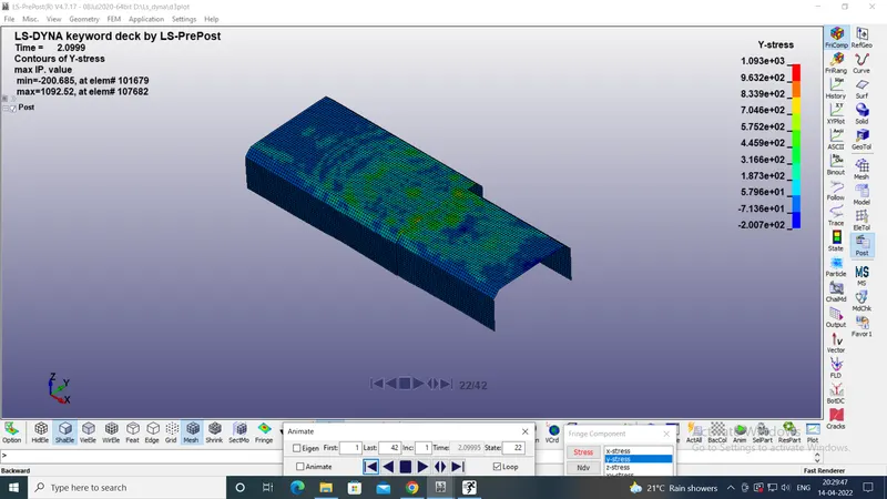
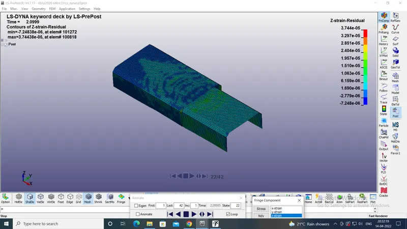
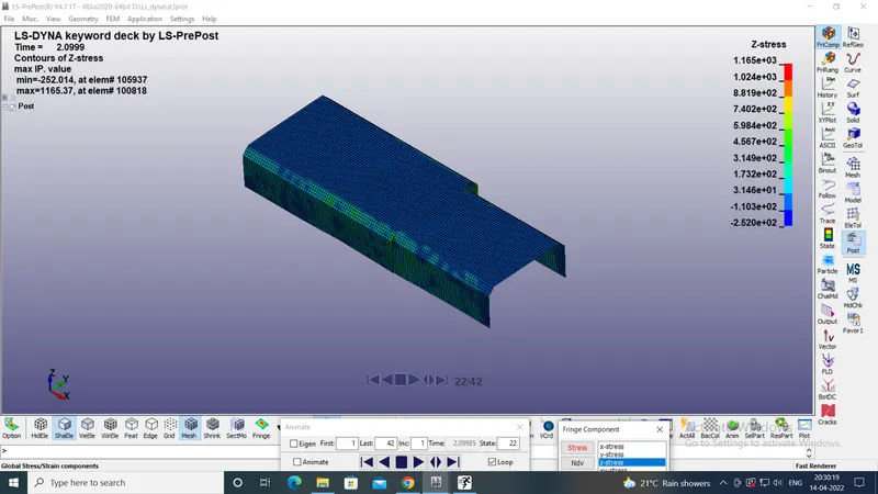
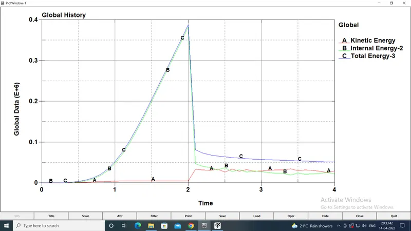
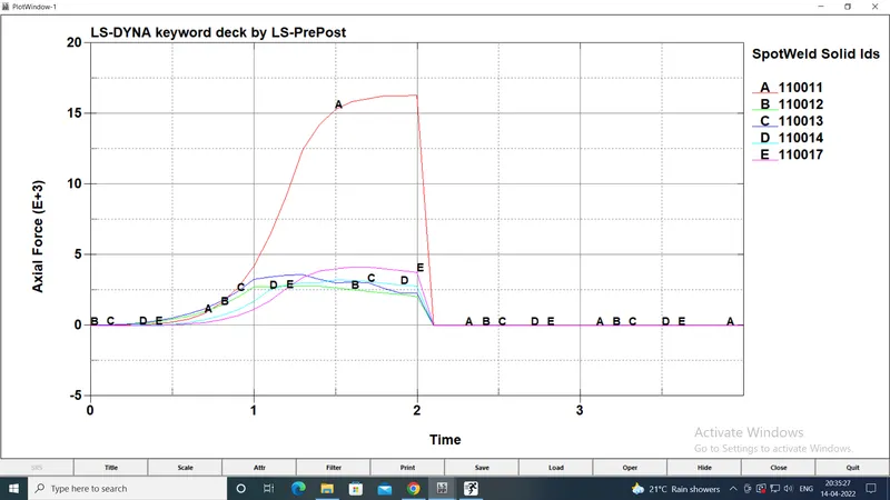
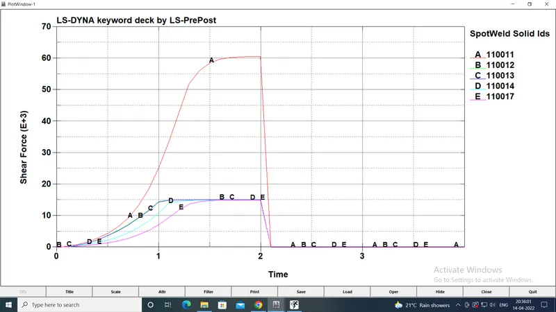
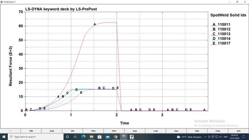
The results are shown below:
| Spotweld beam | Spotweld solid | |
| Maximum von mises stress (gm/mm.ms2) | 914.946 | 1236 |
| Maximum von mises strain | 4.46 e-5 | 3.57e-5 |
| Weld shear force (Maximum) (gm.mm/ms2) | 1.21e+3 | 60e+3 |
| Weld axial force (Maximum) (gm.mm/ms2) | 0.71e+3 | 16e+3 |
| Weld resultant force (Maximum) (gm.mm/ms2) | 1.41e+3 | 62.5 e+3 |
| Weld Failure at (ms) | 2 | 2 |
In both the cases, the internal energy and total energy increase upto the point of the weld failure an decrease afterwards. However the values of the energies, weld forces, stresses and strains are different in the 2 cases.
In case 1, the beam elements in the spotweld have lesser strength than the solid elements in case 2. Hence the beam elements fail at lower resultant force than the solid elements.
Due to stronger solid elements, the stresses generated in case 2 are higher than case 1 and the reverse is true for the strains. Similarly the energies generated in case 2 with solid elements are higher than those in case 1 with beam elements.
Conclusion:
It is clear, from the comparison, that the spotwelds modelled using solid elements are stronger than those modelled with beam elements. Hence solid elements can be preferred to model spotwelds more accurately, depending on the specific problem statement.