Week 4- Rolling operation
Objective:
The aim of this challenge is to simulate the sheet rolling operation and find out the equivalent stresses in the model, plastic strain in the workpiece and the directional deformation generated in the workpiece.
Case setup and execution:
First the Static structural module was opened in Ansys Workbench. In the engineering data, from the general non-linear materials, copper alloy NL was added to the material library.
Then the geometrical model provided in the question was imported. The geometry was edited using SpaceClaim. Using the pull option, the length of the workpiece was increased by 60 mm and its width was reduced by 8 mm on each side.
Then the model tab was opened. In the geometry tab from the model tree, the components were renamed. Also the workpiece was assigned the coppper alloy NL material.
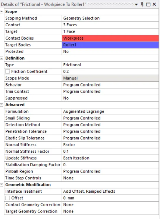
Then in the Connections tab, the 2 contacts - one each between the workpiece & each roller - were defined.
Both the contacts were made frictional with the coefficient of friction of 0.2. The Augmented Lagrange formulation was used. The behaviour was kept program controlled. The normal stiffness factor of 0.1 was used. The stiffness was updated in each iteration. The interface treatment was kept as "Add offset, ramped effects."
Then 2 revolute joints were inserted as "body-to-ground" joint, one for each roller. The inner face of the rollers was selected.
Then the model was meshed with default mesh size. Then body-sizing was inserted for the workpiece, which was given 4 mm mesh size.
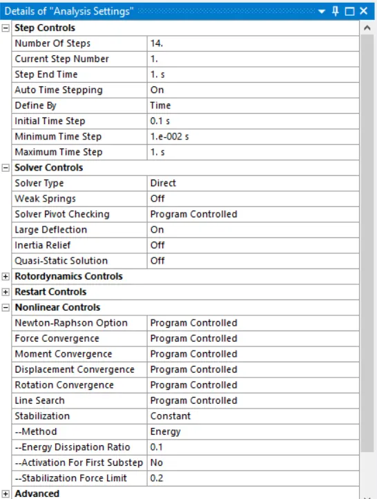
In the analysis settings, 14 number of loadsteps were chosen. For the 1st loadstep, the initial timstep was given as 0.1 sec, minimum timestep was given as 0.01 sec and the maximum timestep was given as 1 sec. For rest of the steps, carry over timestep was turned on, minimum timestep was given as 0.01 sec and maximum timestep was given as 1 sec.
For all the loadsteps, the large deflection was turned on and the solver type was chosen as Direct. In the non-linear controls, stabilization was turned on and constant option was used. Energy method was used with the stabilization force limit of 0.1.
Then a joint-load for rotation was inserted for the revolute joints provided to the rollers. The rotation was applied in 14 loadsteps of 15 degrees each. The directions of rotation of the two rollers were kept opposite to each other.
The workpiece was provided a displacement of 91 mm in negative Y-direction. It was provided in 14 steps, with 6.5 mm increase in each step.
In the solution, the output was requested for equivalent stress for the whole model, the plastic strain in the workpiece and the directional deformation of the workpiece.
Then the model was run and it converged. The results are given below.
Results:
Animation
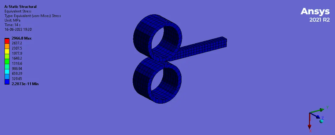
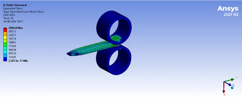
Equivalent stress in the model
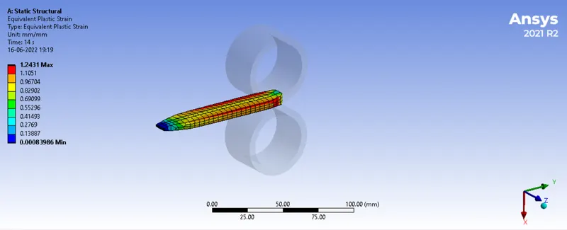
Equivalent plastic strain in the workpiece
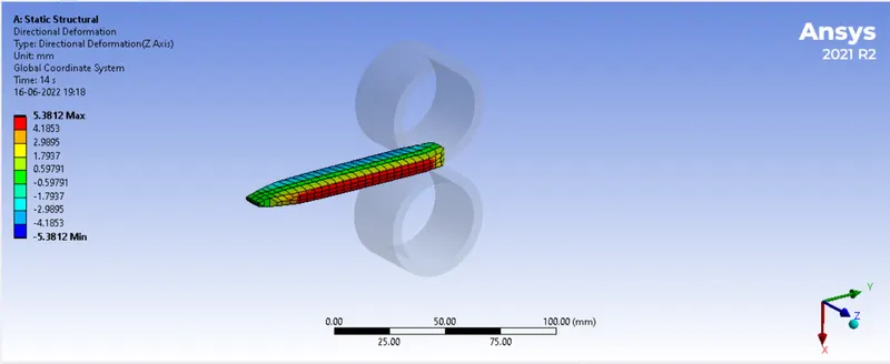
Directional deformation of workpiece in z-axis
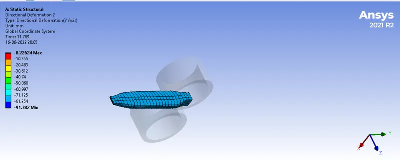
Directional deformation in Y-direction
Conclusion:
Thus it can be seen that the total Y-directional deformation is almost 91 mm which was in fact the displacement value input in the pre-processing. The maximum stresse value is 2966.8 MPa, while plastic strain in the workpiece is 1.24. Due to rolling operation, the workpiece expanded by 5.3812 mm on each side in the z-direction. Thus the simulation is complete. The zip file is attached with the report.