Project 3- Study of cantilever beam with different cross-sections like circular, rectangular and I section and to find out the effect of cross-section on the deflection of the beam using FEA technique using Ansys Workbench and results has to be verified using strength of material deflection equations.
Objective:
The aim of this challenge is to simulate a cantilever beam problem to find the total deformation of the beam for different cross-sections like circular, rectangular and I-section.
Case setup and execution:
First the Ansys workbench was opened and the static structural module was opened.
Then the design modeler was opened and the parts were designed by creating the sketch first and then using the extrude option.
Then the Mechanical module was opened.
The beam was assigned the structural steel material.
The mesh was generated using body sizing of 20 mm.
Then the Analysis settings were decided. The number of steps was 1. Rest of the settings were unchanged.
The cross sectional face at one end of the beam was given fixed support, while the face at the other end was applied the force of 1000 N in negative Y-direction.
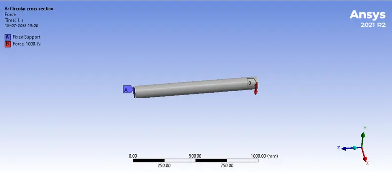
For the output, the total deformation was requested. The model was solved.
Results:
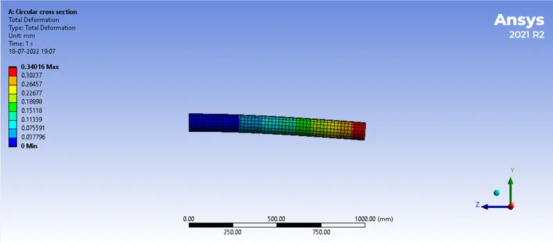
Circular section
Total deformation
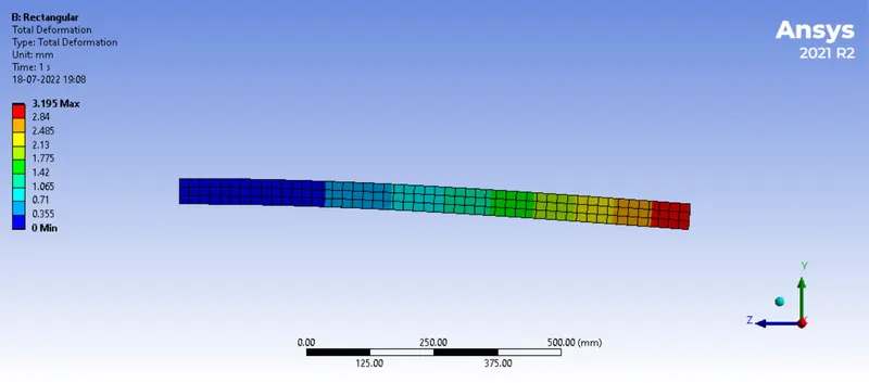
Rectangular section
Total deformation
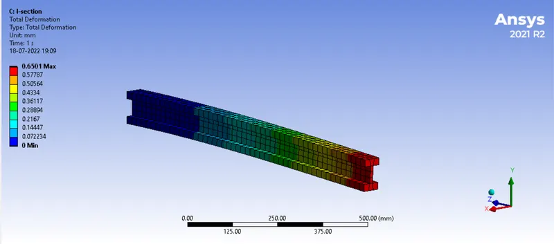
I-section
Total deformation
The deflections of the 3 beams were also calculated manually using the formula
d = F L3 / (3 E I)
where
δB = maximum deflection in B
E = Young's modulus
I = moment of inertia
L = length of the beam
For circular cross section I= 3.14 d^4/64 = 3.14*0.0001/64 = 5e-6
Deflection d = 1000*1/3*210e9*5e-6 = 0.0003174 m = 0.3174 mm
For rectangular cross section I= a^4/12 = 0.05^4/12 = 5.207e-7
Deflection d = 1000*1/3*210e9*5.207e-7 = 0.003048 m = 3.048 mm
For I-section
Deflection d = 0.0006301 m = 0.6301 mm
Comparing both the results for the deflection:
| Result by simulation | Result by manual calculation | |
| Circular section | 0.3401 | 0.3174 |
| Rectangular section | 3.195 | 3.048 |
| I-section | 0.6501 | 0.6301 |
Conclusion:
Thus it can be seen that there is good convergence between the results got by 2 methods. The error is due to the approximate nature of the FEA technique due to meshing. Thus the simulation is validated and is successful. The simulation file is attached.