Week 4-1D Element Creation Challenge
Aim: Creation of 1D elements:
Procedure:
- Download the model provided above:
- Import the geometry undeer import option in IGES format as shown in the image below:
- Go to the midsurface option under Geometry tab to extraction option below auto extract and select the skin offset for both the top & bottom bracket and then go to autoextraction option to extract the fillet surface of solids in the midsurface.
- Now select the Top surafce of solid bracket and click on extract option.
- Now go to components and create a component named as Bracket1 and also create properties under Model tab as PShell with name as Property1 with thickness.
- Now assign this component to the Midsurface of Bracket 1 by going to Tools-Organize option and going to collector and selecting Des component as Bracket 1 by selecting the midsurface of top part of Bracket and click on move button the Bracket one will turn sky blue indicating component created is assigned to the top part of the midsurface of Bracket.
- Repeat the same steps after extracting midsurface of bottom part of the bracket and create components & properties with thickness and assign the same material to the component and use Tool-Organize option to assign the Bracket Bottom midsuface to the component named Bracket2.
- Now delete all the solids and middle surface other than Bracket 1 & 2 components.
- Now go to 2D Automesh and set element size of 5units.
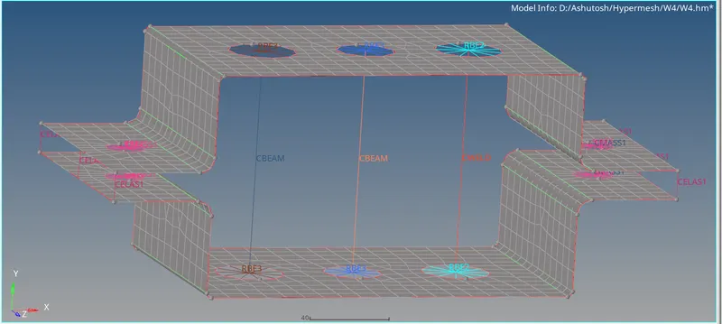
- Now create RBE2 rigid element by going to 1D-rigids.
- Now go to create and select the multiple nodes an calculate nodes and constraining the DOF along translational axis.
- Select the element type as RBE2 and click on create to make RBE2 on the holes and repeat the same steps for the bottom hole as well.
- Now create cross-section of Rod element by going into 1D-Hyperbeam
- Select standard section and standard section library as optistruct and standard section type as Box and click on create to open Hyperbeam section.
- Enter the section dimension of rod as mentioned in the question above.
- Now create the Property for Rod as PROD and assign cross section.
- Now create a Rod Component and assign property and material to that and assign the CROD element to it by going into Tool-Organize-Element selection and des component as Rod and clicking on move to assign.
- Final Cross-section of rod can be viwed form 1D-Detailed element representation.
- Now create RBE3 all constraints Component and then create 2 RBE3's by going into 1D-RBE3 option as RBE2 was created and constraint all its translational & rotational DOFs.
- RBE3 for Beam is created in the location b as shown in the image in the question and assign to the RBE3 all constraint component with the help of Tool-Organize option.
- Now create the Beam component and its property as PBEAM with cross-section as I-section by going ino 1D-Hyperbeam-Optistruct-Standard section-I with dimensions.
- Now assign the section to the property of beam.
- Now create a Beam component and assign the property to it .
- Now create a Beam element by going to 1D-bars and create Element types as CBEAM and property as Property4 for Beam and select the centre Node for 2 RBE3's and orientation along Y-axis.
- Now assign the Beam element to the Beam component by Tool-organize option with des component as Beam.
- Now create a component of RBE3 x&y constraints and then create another 2 RBE3's at the C location with DOF along x & y constraints.
- Assign the RBE3 elements to the RBE3 x&y constraint components.
- Now create a Bar compnent and property as PBAR with Cross as section of Bar under 1D-Hyperbeam-Standard section-Optistruct-Cross with dimensions mentioned in the question above:
- Assign the property to the Bar components.
- Now create a Bar element in the similar manner to the beam element type as CBAR.
- Now add mass at the location d & e after creating a component for RBE2 under 1D-rigids with all dof constraints.
- Now add mass by going into 1D-masses option with mass as 10 units,element type as CMASS1 and selecting the centre nodes of RBE2's created at 4 locations on d&e.
- After adding mass CMASS1 appears at the centre of 4 RBE2's.
- Now create a Spring component and property of Spring as PELAS with stiffness as 0.001.
- Now go to 1D-springs for creation of spring element with allowable DOF along Y-axis as dof2 with element types as CELAS selection of one node each from Top & Bottom Bracket meshed midsurface with property assignment.
Conclusion:
The 2D meshing of midsurface was done and 1D element creation of various types with various cross sections and Dofs was executed.