Week 2 Railwheel and Track
Objective:
The aim of the challenge is to simulate the motion of a rail wheel on a track and find out the total defromatino and equivalent stresses & strains.
Case setup and execution:
First, the Ansys Workbench was opened and the given model of the railwheel and track was imported in the Static Structural module. Then the Ansys Mechanical was opened to set up the model.
In the Ansys Mechanical, first the contacts were defined: first between the wheel & the track and the second between the shaft & wheel.
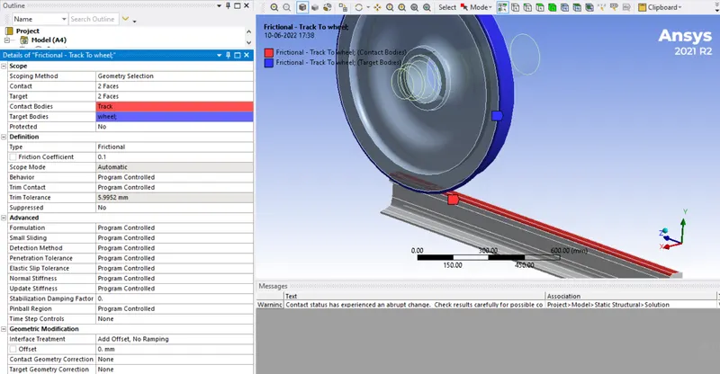
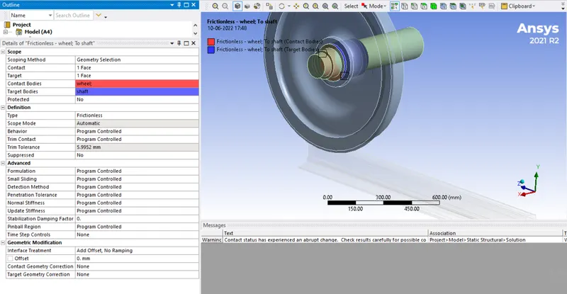
The contact between track and wheel was made frictional with coefficient of friction as 0.1. The contact between the shaft and the wheel was made frictionless. The images of both are attached below:
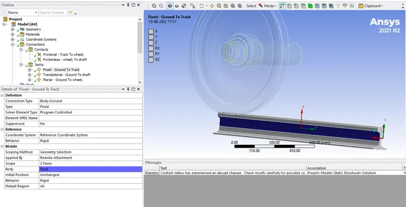
Then the joints were specified. First, a fixed joint was provided to the track by selecting the opposite faces of the rail as shown below:
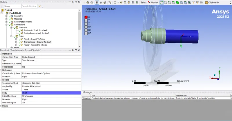
Then the translational joint was provided to the shaft, which was free to translate in local positive x-direction as shown below:
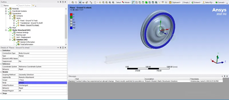
The wheel was provided a planar joint, wherein it was free to rotate about local z-axis, which coincided with its own axis. It was free to translate in local X & Y directions.
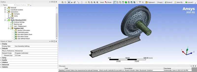
Then the model was meshed with the element size of 35 mm as shown below:
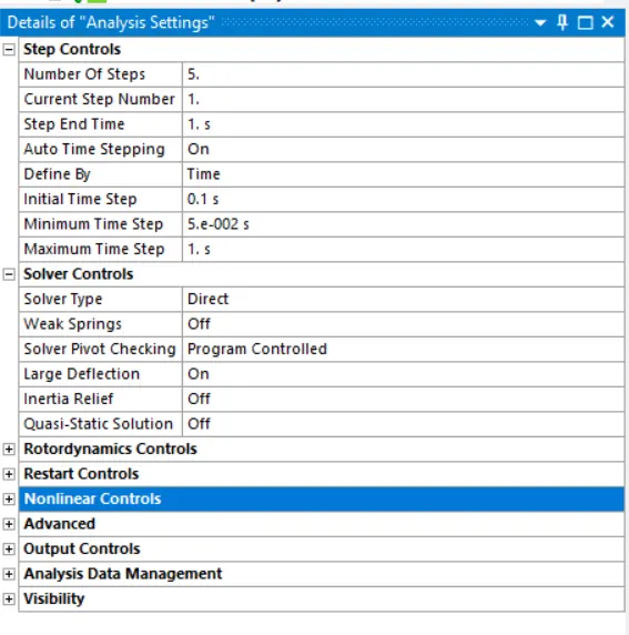
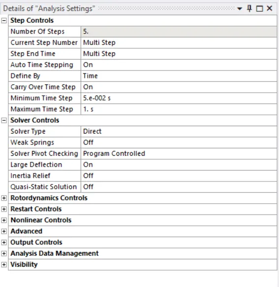
In the analysis settings, 5 steps were chosen. For 1st step initial timestep was chosen as 0.1 sec, while carryover timestep was turned on rest of the steps. For all the steps, minimum timestep was 0.05 sec and maximum timestep was 1 sec. Also the large deflection was turned on as shown below:
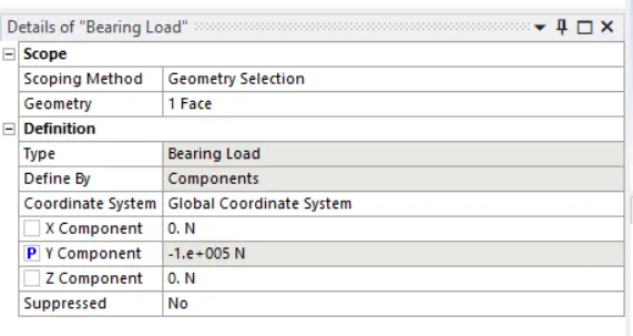
Then by right-clickng on Static structural, the bearing load of 100,000 N was applied on the shaft in the global negative Y-direction. This value was parameterised.
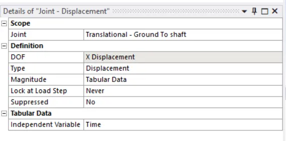
Then the joint load was applied as displacement to the translational joint given to the shaft. The displacement was given in tabular form. It was 500 mm in 5 steps, with 100 mm rise in each loadstep.
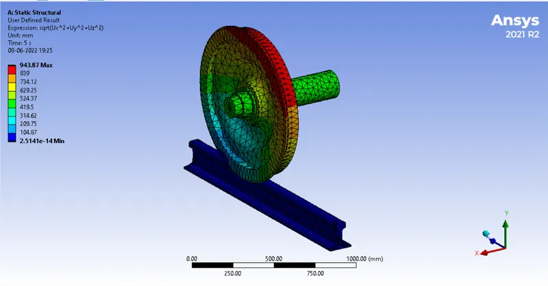
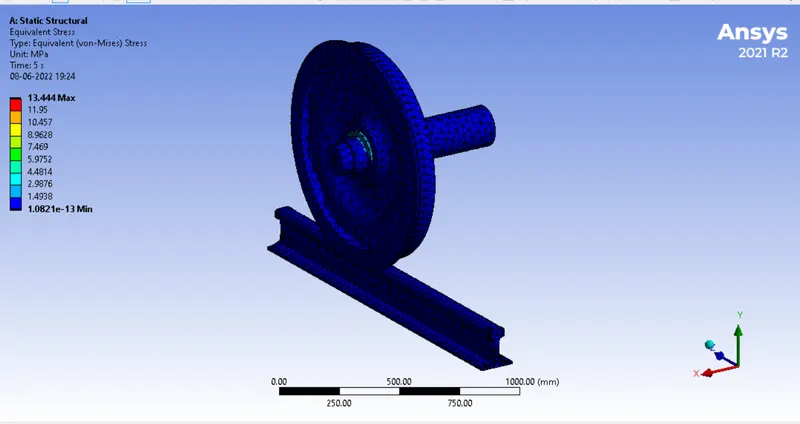
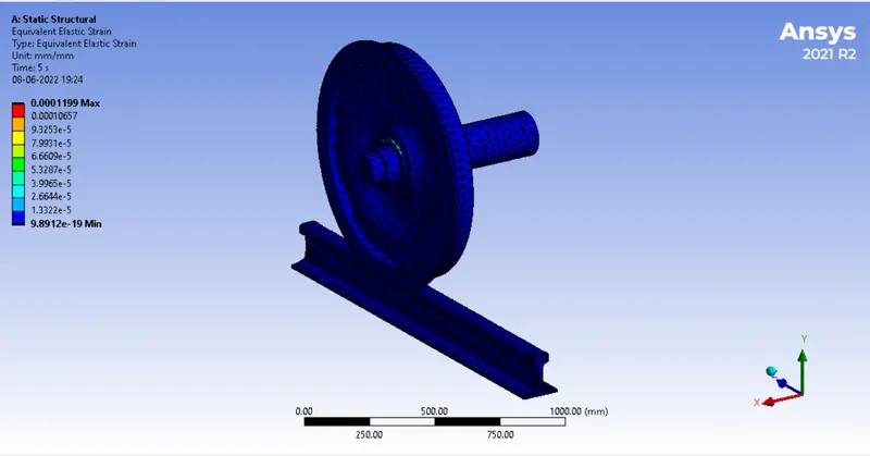
Then in the solution, the total deformation, equicalent stress and strain and the user defined results were inserted. For the user defined result, the expression for the total deformation was input. All these output requests were also parameterised.
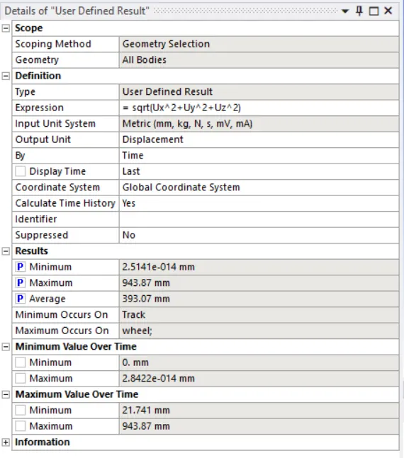
The model was run. The results are shown below.
Results:
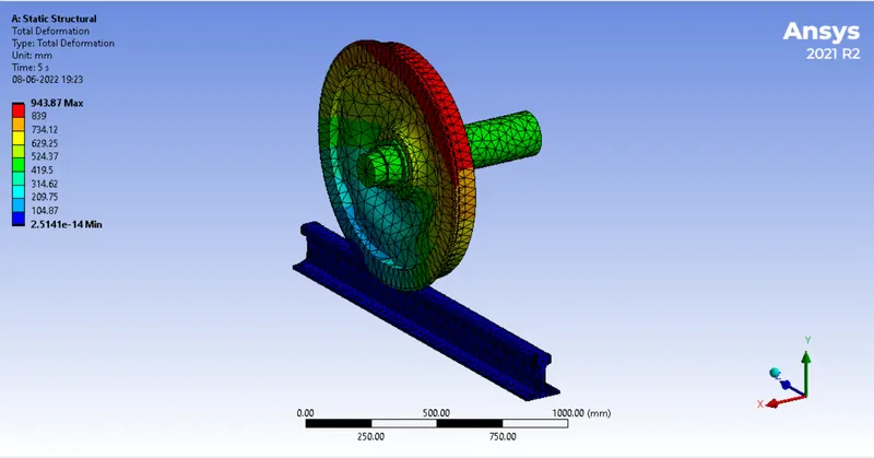
Total deformation:
User derfined result:
Equivalent stress:
Equivalent strain:
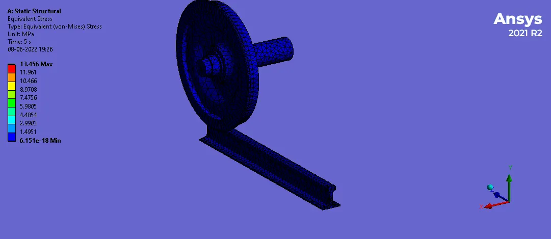
Animation:
Then the parameters tab was opened from static structural module and the bearing load of 500,000 N was input. Then Evaluate all results button was clicked to solve. The results are given in below table:

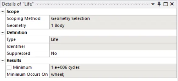
In both the cases, the life was calculated to be 1.0 e+6 cycles as shown
Conclusion:
It can be seen that the user defined result for total deformation is equal to the total deformation values calculated by the solver. However the total deformation is more in second case with bearing load of 500,000 N. This is because, the additional load has caused more deformation. Thus, as userd defined and solver calculated results are same, the simulation can be considered as accurate.