Week - 4 - 2D meshing for Plastic components
Aim:
The aim of this challenge is to perform the 2D meshing of the given components after performing the geometry cleanup and extracting the midsurface. The elements are supposed to meet the mentioned quality criteria.
Procedure:
- The given model was opened in ANSA using File-open command.
- The geometry check was performed to find out any geometrical errors. No geometrical errors were found in the model.
- The midsurface was extracted manually using the Faces-Offset command. The thickness of each component was measured and half of it was given as offset distance. The newly created offset surface was given new PID using “Ask Always” option and the thickness was made equal to the component thickness.
- The manual midsurface option was used because the components had varying thicknesses.
- The midsurface for Teeth and Threads was taken as per the procedure mentioned in the FAQ article in the question and using the ‘Rotate’ command to copy Mid surface entities.
- In one of the faces, there was a gap. As it was a circular face, a 3-point circle was created using Curve-create option and choosing 3 points in the edge of the face. Then a new surface was created at the place of the hole using the newly created circle and edges of the hole.
- In all the components the macros were joined such that they form rectangles as far as possible. Then the length of the perimeter and the macros was given as 1 mm using perimeter-length option.
- By pressing F11 key, the quality criteria were input. Using Mesh parameters tab, the average length was input as 1 mm.
- Then each of these macros was meshed. First the macros with difficult shapes were meshed, then the simple macros were meshed.
- To remove the tria elements, Reconstruct command was used. Also the number of elements on the perimeter or the edges of the macros were also changed to remove trias. In some case, split and join option was used to cnvert tria elements into quad elements.
- Smooth option was also used to smoothen the mesh.
- There was one red con on one of the surfaces which could not be removed using Faces-join option nor could it be deleted. Hence Fill-hole option was used to fill the small gap and then join option was used to toggle the resultant double con. It is shown in below image:
- Grids-move-free option was also used to move the nodes to remove the OFF elements.
- Sometimes the failed elements were deleted and new ones were created at the same place.
- In one of the teeth, 3 elements were failing, which could not be rectified using any method, due to closely spaced nodes on the triple cons. The faces could not be joined either due to different PID. Hence the original face was deleted and the new face was created with the same PID. Now the entire face was cut from one of the nodes on the triple cons. Then it was again meshed and the OFF elements were removed. The new face was given its original PID again using the “Set PID” option.
- For the thickness, the desired thickness was assigned to all the different properties shown in the following image:
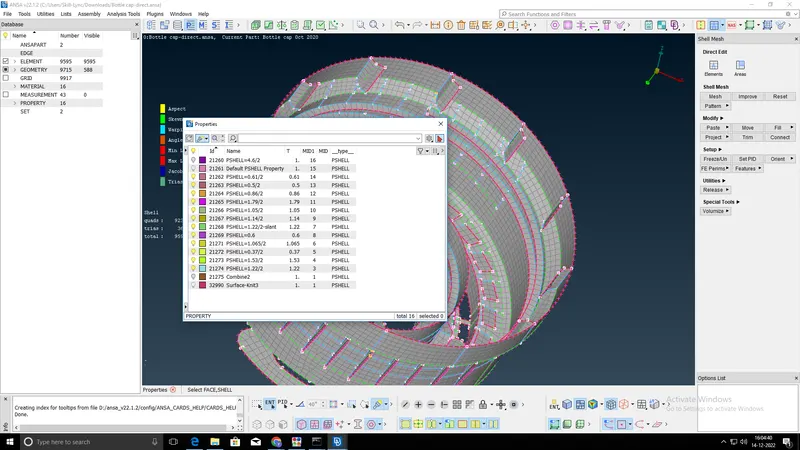
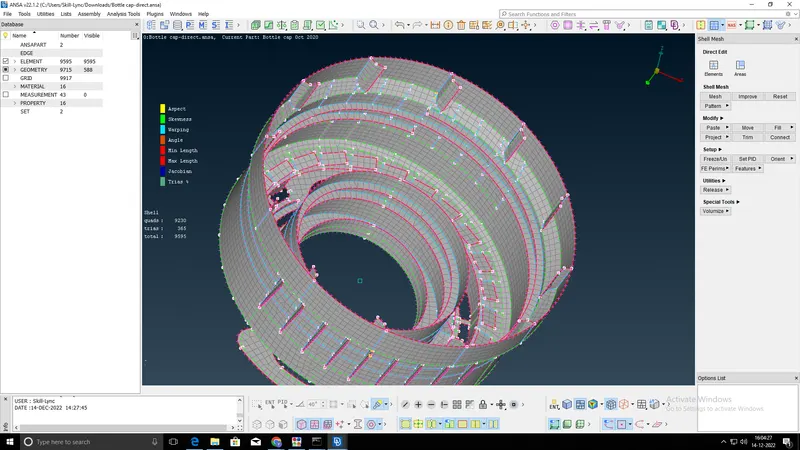
- The element quality criteria tab was opened using F11 key. Under the "Presentation parameters" tab, the "Draw shell as solid" option was ticked to enable the same.
- The following image shows that there are no off elements in the model:
Learning Outcomes:
Learned how to 2D mesh as well as mesh modification using reconstruct, smooth, Num+/- , split, move and join commands. Learned how to delete and create new elements. Set PID for a face. Assigning different properties for different thicknesses etc.
Conclusion
Thus the model was meshed successfully. Please find the model attached to the report.