Assignment 5-RADIOSS Interfaces & Study of Effect of Notches Challenge
Objective:
The aims of the challenge are to learn how to model contacts in Hypermesh and to study the impact of notch on the stress distribution in the component. Thereby, the aim was also to learn how to create and remove notches from the components. Also 2D meshing was to be performed on a component given in the question.
Case setup and execution:
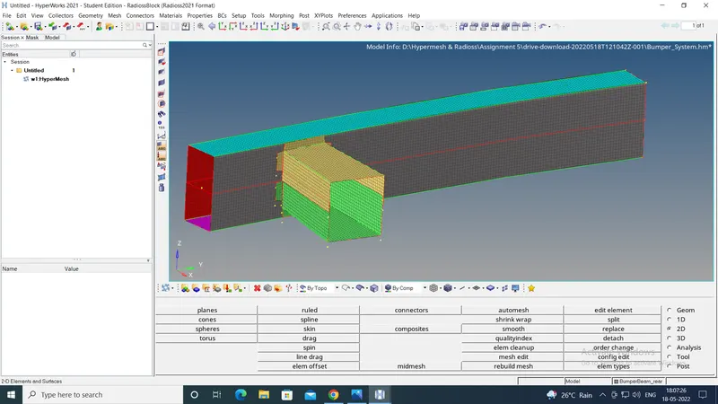
The challenge involved 2D meshing of a given part called "Bumper_system". For this the .hm file was imported in Hypermesh. In 2D panel, "automesh" option was selected and a 2d mesh of size 6mm was created. The screen shot of the same is attached below:
After this the challenge involved 6 cases of simulations as described below:
Case 1:
In this case, the given Radioss starter file named "Crush_tube_0000.rad" was to be run as it was given and at the output, part-wise internal energy, rigidwall forces and contact forces had to be checked.
To get the contact forces and part-wise internal energy plots, 2 new cards had to be created.
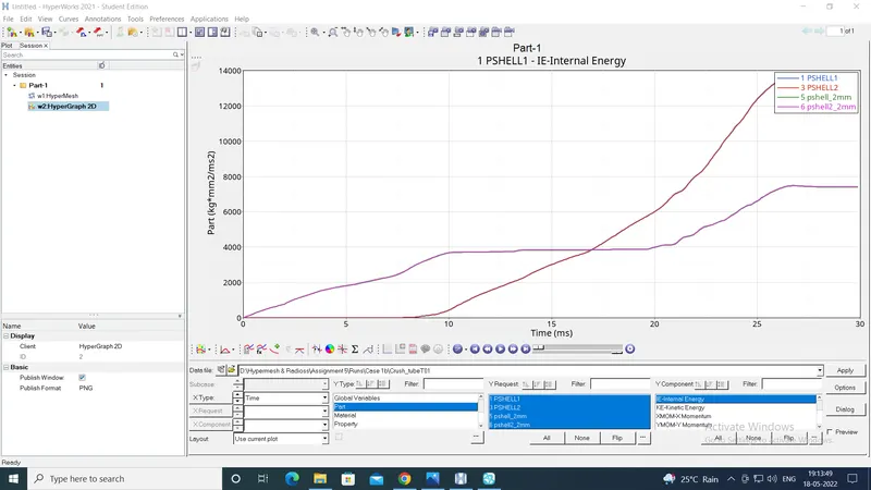
The TH/Part was created first. From the Menu bar, "Tools" option was selected, under which "Create Cards" was chosen. In this, under "TH", "Part" was chosen. In this, all the shell components were selected. This ensured the part-wise internal energy plots at the output.
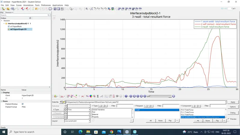
Then to get the contact forces at the output, in the model browser, the "Output Blocks" option was right-clicked, under which "Create" option was chosen. Then the newly created output block was selected and in the entity window, the 2 contact groups- seamweld and self contact- were chosen.
The images of the results are attached below:
Case 2:
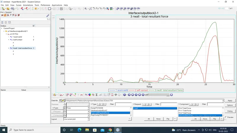
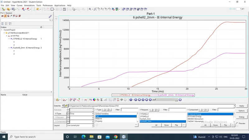
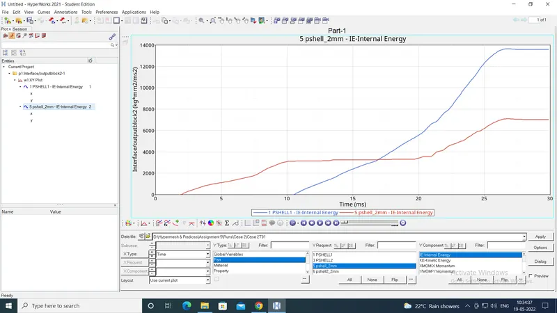
In case 1, the Inacti was set as "default". In case 2 the Inacti was changed to 6 and the model was run. The results are below:
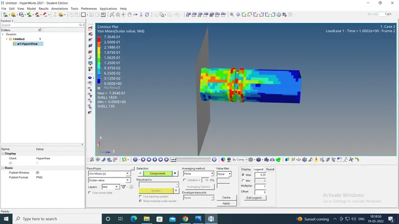
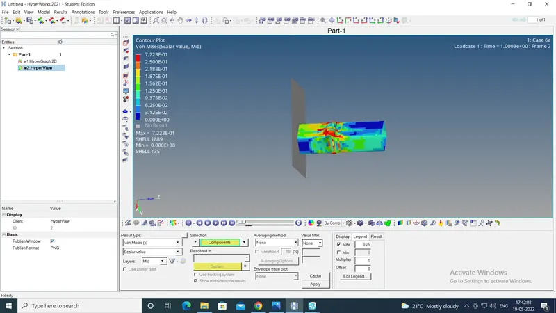
The von mises stresses at the time of 1 ms are:
Case 3:
In this case, the type 11 edto-to-edge contact was to be added. To create this contact, in the model brower, the "Groups" optionwas right-clicked and the new group was created. In the entity window, the type 11 was selected as type of contact and the rest of the properties of the contact were kept same as type 7 contact already present. The master and slave parts were chosen to be the same components.
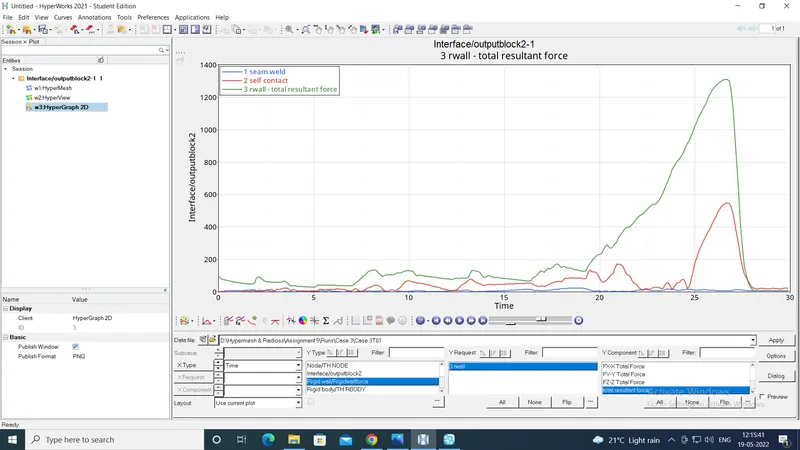
The images of the results are shown below:
Case 4:
This case involved removing both the notches and removing boundary condition on rigid body node and then running the model.
This time the model from Case 3 was imported.
To remove the notches, from the "Tool" panel, the "project" option was used to project the selected nodes to the plane of the adjacent surface. For the nodes on the fillet, "align nodes" option in "node edit" was used.
To remove the BC on the rigid body node, first from "View" option on Menu bar, "browser-Hypermesh-solver" was selected. Then from the solver browser, the BC option was chosen and the given BC was deleted by right-clicking on it.
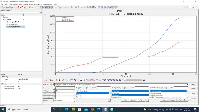
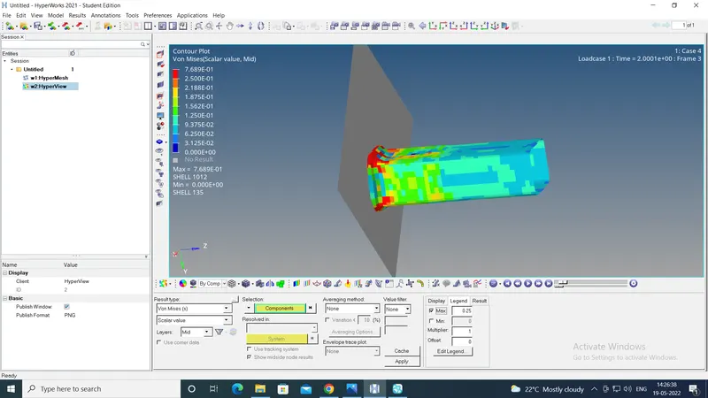
The model was run. The results are shown below:
Case 5:
In this case, a new notch had to be created in the middle of the components. The model from case 4 was imported.
To create the notch, the "translate" option from the "Tool" panel was used to translate the nodes in the desired direction, normal to their original surface. From case 1 model, the depth of the notch was checked, which was 4 mm. Hence the nodes were translated 4mm.
For the nodes on the fillet, the translation was of 5.657 mm which is the diagonal distance (hypotenuse of the right angle triangle of sides 4mm). They were translated in the direction of the diagonal chosen by selecting 2 nodes, one on each of the opposite faces.
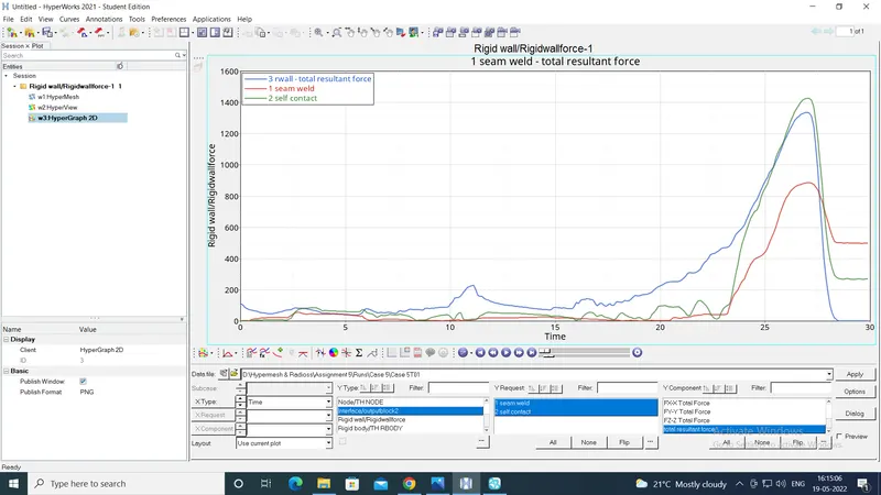
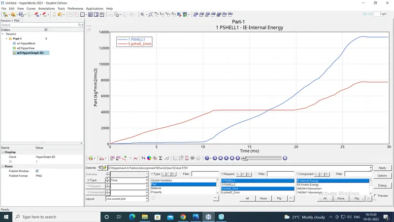
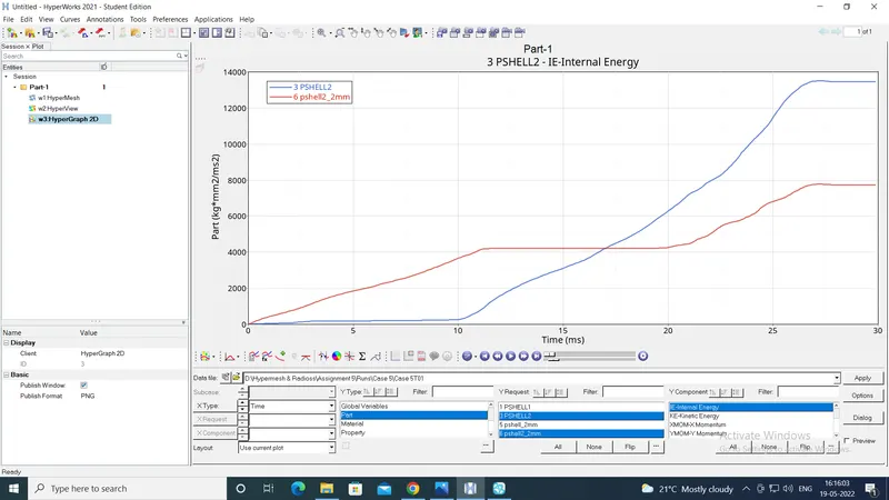
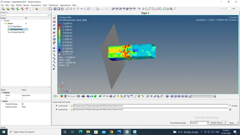
Then the model was run. The results are shown below:
Case 6:
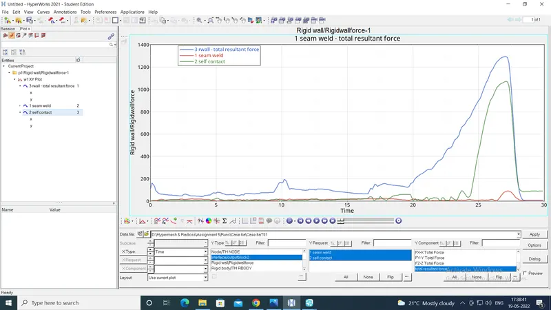
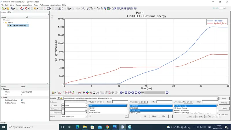
In this case, the notches were to be created just on the 2 opposing faces, instead of all the faces. Hence from the model of case 5 the notches on 2 faces were removed using the procedure in case 4. The results of the simulation are shown below:
Results explanation:
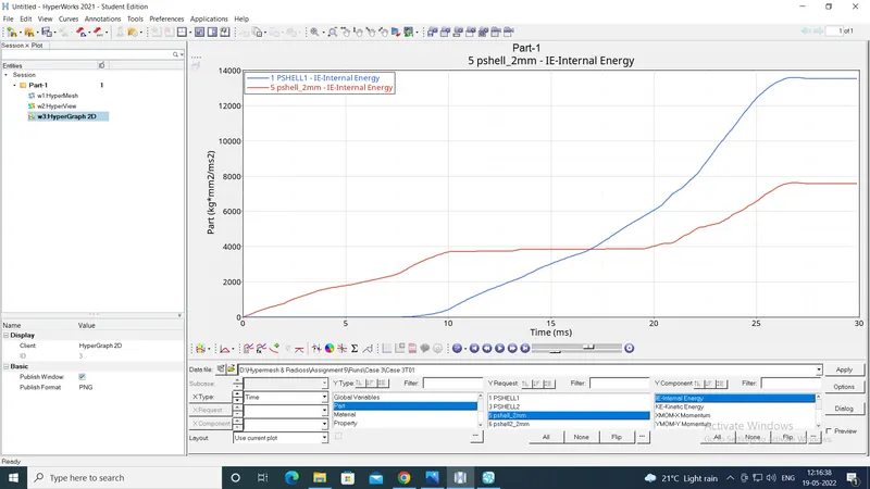
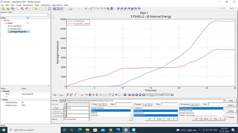
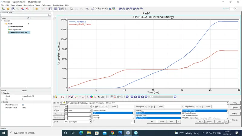
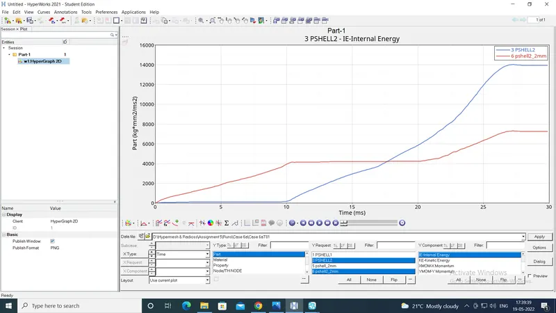
From the graphs, it is clear, that the internal energy plots of the components are almost similar in all the cases. In each case, the internal energies of the shell parts 5 and 6 rise first and are more than the other 2 shell parts. But after a point, the internal energies of shell parts 1 and 3 rise and become more than those of the parts 5 and 6.
This is because, during the collision, the shell parts 5 and 6 collide with the rigid wall first and get crushed, which raises their internal energy. But when these parts are completely crushed, the shell parts 1 and 3 start getting crushed, which raises their internal energy.
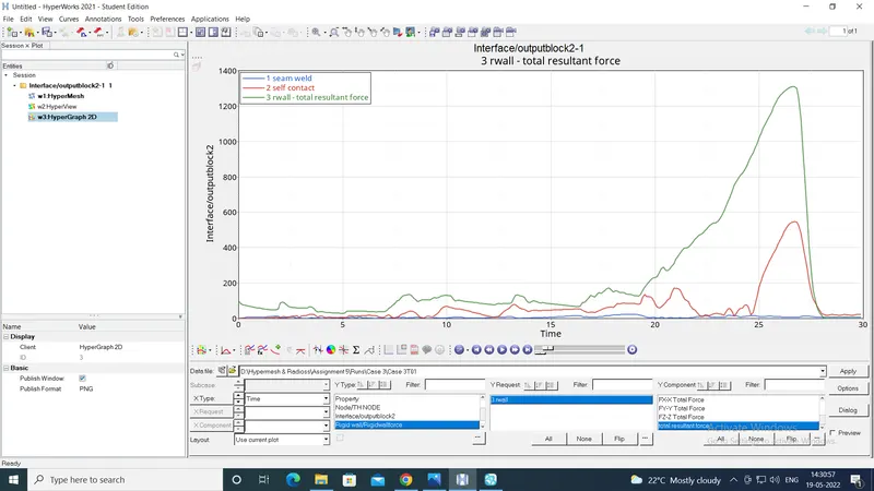
From the graphs, it is also clear, that although the internal energy plots of the components are almost similar in all the cases, the graphs showing the contact forces are not similar. The values of contact force in the self contact are different in different cases.
Case 1 and Case 2 had only type 7 node to surface contact. But in Case 3 both type 7 and type 11 edge to edge contact were given. Hence the contact area in case 3 is larger than that in cases 1 and 2, because node-tosurface contact cannot recognise the edge-to-edge and surface-to-surface contact. With same graphs of internal energy, this resulted in stress being distributed over larger area in case 3. Hence the magnitude of the contact forces is lower in Case 3 than in cases 1 and 2.
This reasoning is further substantiated by the fact that, the magnitude of the rigid wall forces is the same in all the 3 cases. This is because the type 7 and type 11 contacts are for the shell components, which do not affect the contact between the shell parts and the rigid wall.
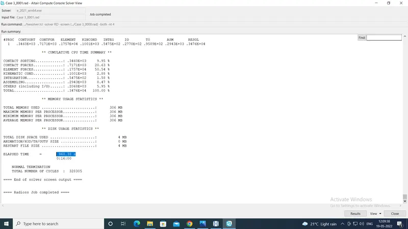
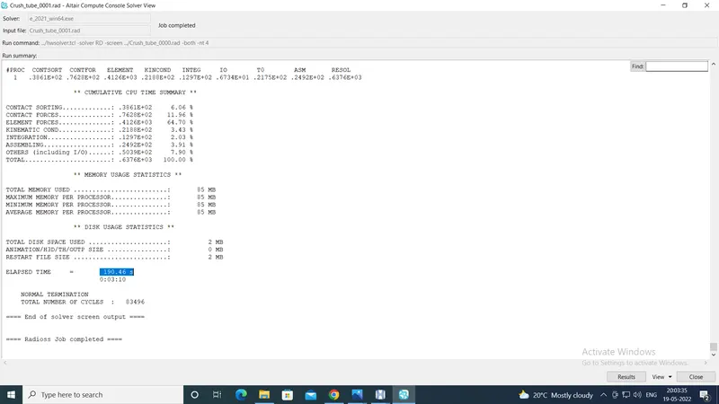
As the contact area incresed in case 3, the computational time also increased. In case 3 it was almost 960 seconds, while it was around 182 seconds in case 2 and 190 seconds in case 1. The images are shown below:
For case 3:
For case 2:
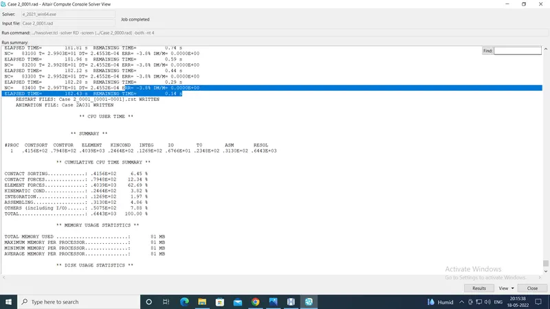
For case 1:
Then the cases 4,5 and 6 show the effect of notches on the results.
In case 4 there are no notches, hence the stress concentration is at zone of collision with the rigidwall. But in case 5 with the notch in the middle, the stress concentration is more in the zone around the notch.
This is also evident in case 6, which has notches on only 2 opposing forces. Here the stress concentration is more near the notch, whereas on the face without a notch, the stress concentration is lesser.
Conclusion:
Thus it is clear, that
1. Sequential crushing of the shell components causes sequential change in the internal energies of the shell parts.
2. The combination of type 7 and type 11 contacts increases contact area under calculation, giving more elaborate results.
3. The presence of notches introduces stress concentration zones, reducing the strength of the components.
The model files are attached in zip format with this report.