Week 2 Bevel Gear Challenge
Objective:
The aim of the challenge is to perform the simulation to know the total deformation and equivalent stresses and strains in the bevel gear pair provided.
Grid dependency test:
Here, grid refers to the mesh on a component. Grid dependency test tries to ascertain how the results of a simulation change with change in the grid size i.e. the mesh size. It is used to determine the optimum mesh size for the given simulation problem, in terms of accuracy and solution time.
Case setup and execution:
First the "Static structural" module was opened in Ansys Workbench.
Then the geometrical model was imported. Then the "model" was opened in the "Ansys Mechanical".
Then the contact between the two gears was defined by selecting the faces of the teeth of the gears. The contact was made "frictional", the behaviour was "symmetric", the "Augmented Lagrange" formulation was used and the for the interface "adjust to touch" option was used.
Then the both the gears were provided with the revolute joint. In the Connections, joint-revolute was inserted and "body-to-ground" connection was specified. The inner faces of the gears were selected to define the respective joints.
Then the model was meshed using the element size of 6 mm. The mesh size was parameterised by ticking the box next to mesh size tab, so that "P" appears in the box.
In the analysis settings, the number of load steps was chosen as 6. The auto stepping was turned on. The substeps were defined using time. The initial timestep was input as 0.001 sec., the minimum timestep was 5e-04 sec. and maximum timestep was 1 sec.
For rest of the load steps, the "carry-over time step" was turned on and the minimum timestep was changed to 5e-04 sec.
For each loadstep, maximum timestep was kept at 1 sec.
The "large deflection" option was turned on.
Then by right clicking on "analysis settings", "joint-load" was inserted. Using this, one gear was provided the rotation about local z-axis. The rotation was provided in tabular form. It was 0 degrees at 0 seconds and increased by 20 degrees in each load step upto 120 degrees.
The other gear was provided the moment of -100 N-mm about the local z-axis using the joint-load option. It was ensured that the rotations of the two gears are in opposite directions.
The the "Solution" tab was right clicked to insert the desired outputs of total deormation, equivalent elastic strain and equivalent von mises stress. The maximum, minimum and average values of these properties were also parameterised, to check the effect of the changing mesh size on them. This is called the grid dependency test.
Then the model was run using the solve button. It ran smoothly and converged. The results are explained below.
Results:
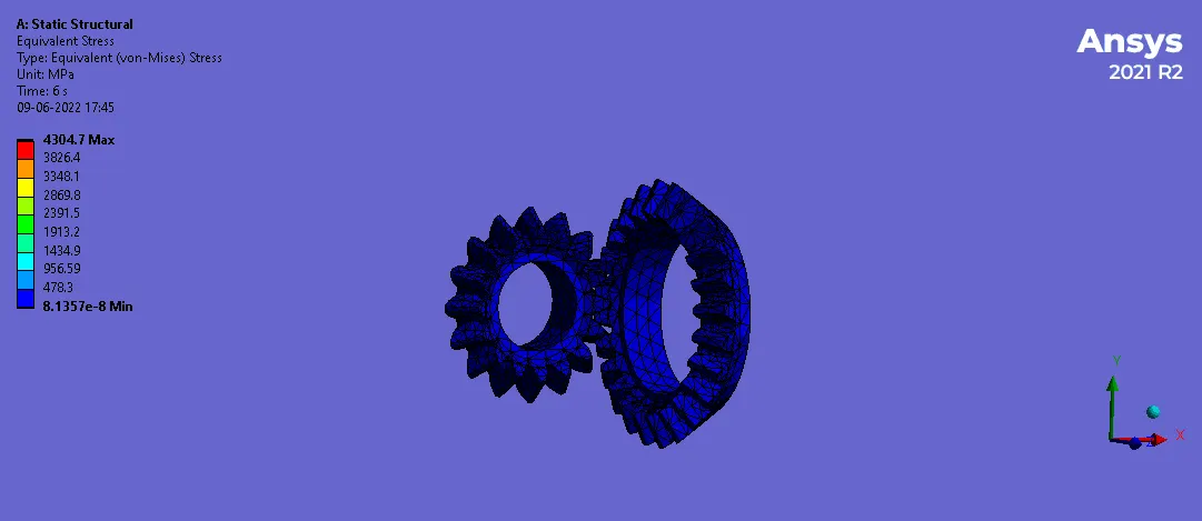
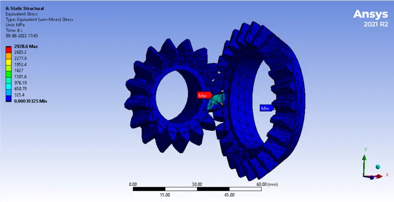
Equivalent stress
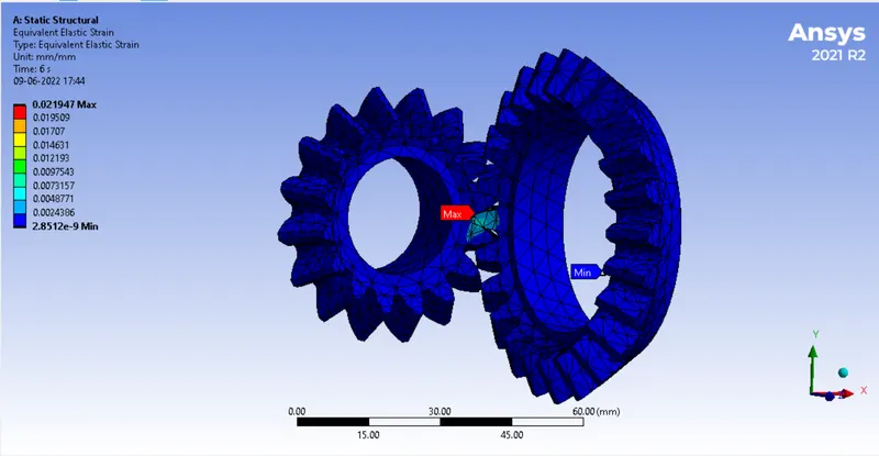
Equivalent strain:
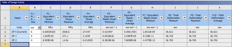
As the mesh size was parameterised, a "Parameters" tab opened at the bottom of the Static structural module in the Workbench. This "parameters" tab was opened and the mesh sizes of 5 mm and 4 mm were inserted. Then the "Evaluate all results" button at top left corner was clicked to obtain the results for 5 mm and 4 mm mesh size.
The results for all the mesh sizes are provided in the image below:
Conclusion:
Thus, the results of the simulation make amply clear, the effects of mesh size on the results. As the mesh gets finer, the stress and strain values are getting accurate. This is further substantiated by the total deformation values, which remain almost similar in all the 3 cases. Hence, with smae boundary conditions and loading conditions, the changes in results would only mean that they are getting more accurate with reducing mesh size.