Assignment 2-RADIOSS Engine File Editing & 3D Meshing Challenge
Objective:
The objective of this challenge is to learn to calculate the speed of shock wave through a part and thereby the size of the timestep. The aim was also to learn to edit the Engine input file to input the termination time and time-range at which animation file is to be written. Also the 3D meshing exercise was to be performed using tetra and hexa elements with specified quality criteria.
Explanation:
First, the given starter file FIRST_RUN_0000.rad was opened in Notepad++ to check the material properties. It was observed that the unit system was gm-mm-ms and the material properties were extracted as shown below:
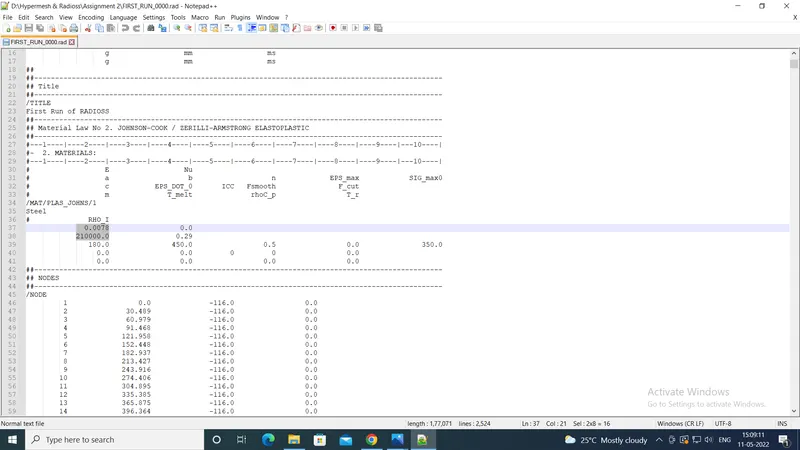
Thus the density = 0.0078 gm/mm3 and the Young's modulus E= 210000 gm/mm.ms2.
1. Hence the speed of the sound wave in steel rail 'c' = `sqrt`E/density = `sqrt`210000/0.0078 = 5.19 e3 mm/ms
Thus c=5.19 e3 mm/ms
2. The time taken by the shock wave to travel from one end of the rail to the other 't' = length of rail/speed of sound = 1000/5.19 e3 = 0.1926 ms.
Thus t=0.1926 ms.
3. Time for sound to travel the length of rail = 0.1926 ms
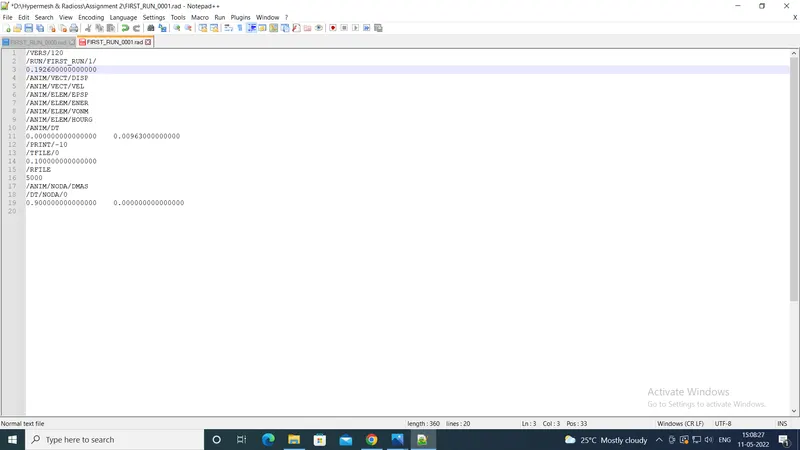
After getting the value of time, this value of time was input as the termination time in the Engine file. Also this time value was used to calculate time-range (tfreq) to get 20 animation steps.
5. Thus Tfreq = 0.1926 ms/20 = 0.00963 ms.
Tfreq = 0.00963 ms
4. The values of termination time and Tfreq were inserted in the Engine file FIRST_RUN_0001.rad by opening it in Notepad++ and the file was saved.
6. /print value is also set to -10.
The screenshot of the same is provided below:
7. After this, the 3D meshing was carried out on the given models.
The tetra meshing was done on the cover and hub parts. To perform the tetra meshing, first the model was opened in Hyperworks.
In the 3d tab, the "tetramesh" option was opened. Under this, the "tetramesh parameters" tab was opened, in which the tet collapse value of 0.15 was inserted. After this, the "Volume tetra" option was opened, in which the element size of 5 mm was specified. The closed solid surface was selected and the "mesh" button was clicked. This created the tetra mesh on the part.
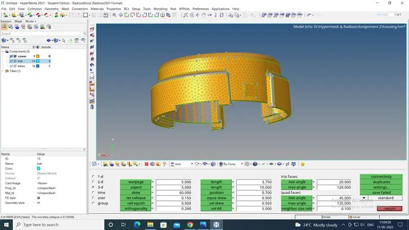
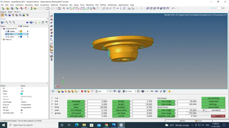
The same procedure was repeated for both the 'cover' and the 'hub'. Then in the "tool", check elements tab was opened and in 2d panel, "tet collapse' button was clicked to check whether any elements failed. In both the cases none of the elements failed the criteria, as shown below:
After this, the hexa meshing was done on the model provided i.e 'arm bracket.hm' model using following steps:
First all the parts except the 'base' were hidden. Then a 2D mesh using "quad only" elements was created on the top surface of the base. Then in 3d panel, "element offset" option was opened. The quad elements created were selected and the surface on the thickness of the base was chosen to offset the elements along. This created a hexa mesh for the 'base' part.
After this, the hexa elements were masked. For this in 'tool', 'mask' option was used. For elements selection, the 'by config' option was used to select the 'quad4' elements and these were masked.
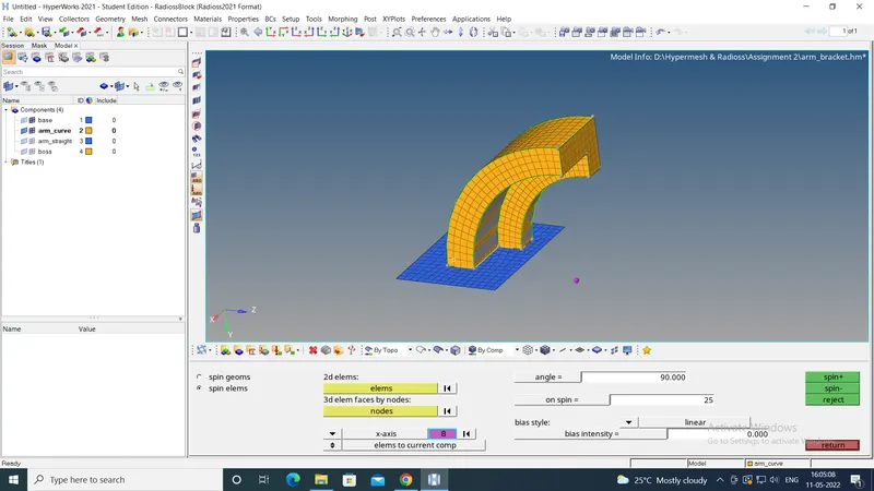
Now to mesh the arm_curved part, the 'spin' option in 3d panel was used. For this, first the origin of the arc of the curved arm was to be found. To do this, in 'Geom' tab, 'distance' option was opened, under which 3 nodes option was chosen. 3 nodes were selected on the edge of the arm_curved and then the 'circle center' button was clicked. This gave the origin of the arc.
Then the 'spin' option was opened. In this the elements were selected from the 2D surface mesh of the 'base'. The angle of spin was given as 90 degrees and on spin 25 elements were specified. Then global X-axis was chosen as the axis of spin while the origin of the arc was chosen as the base point. Then 'spin-' button was clicked. This generated the mesh for the arm_curved. The image is hown below:
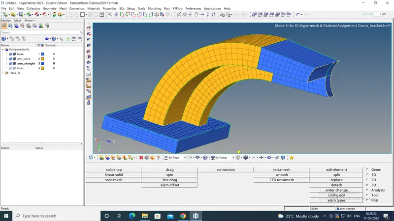
Then 'arm_straight' part was to be meshed. For this the "linear solid" option on the 3d panel was to be used. This requires the elements upto which the mesh needs to be extended. To create these elements, the surface of the 'arm-straight' adjacent to the 'boss' part was meshed using the 2D quad elements. While meshing, the elements on this face were made equal to the elements on the face of the 'arm_curved' part.
Then in "tool", 'faces' option was used to 'find faces' on the 'arm-curved' component. This created a layer of 2D quad elements on the 3D hexa mesh of the 'arm_curved' component. Then under the "linear solids" option under the 'from' option, the elements on the face of 'arm_curved' were selected. Under 'to' option elements of the 2d mesh on the face of the 'arm_straight' were selected. For alignment 3 nodes on 'arm-curved' were selected and the exact corresponding nodes on the meshed face of the 'arm_straight' were selected. The density was chosen as 12 and 'solids' button was clicked. This generated the mesh for the 'arm_straight' part. Then the 'organise' tool was used to move the mesh to the 'arm_straight' component. The image is provided below:
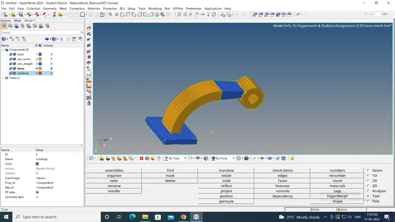
Now the 'boss' component was to be meshed. To do this, first one of the circular faces of the 'boss' were selected and meshed using 2D quad elements. The number of elements were matched with that on the 'arm_straight' component. Also the number of elements on the inner and the outer circular edges was also matched ot get an uniform mesh.
Then the 'project' tool was used to project a node on the 'arm_straight' component to the other circular surface of the 'boss' component. The node was duplicated and 'surface normal' option was used to project the node.
Then the 'solid map' option on the 3d panel was selected. In this 'source geom' option was set to none, elements from the 2d meshed circular surface were selected to drag, 'dest geom' was selected as the opposite circular face, in 'along geom' option 'mixed' option was chosen. In this, the node path was given along the nodes of the 'arm_straight' part. Also the line on the cylindrical face was chosen. Then the 'mesh button' was clicked to generate the hexa mesh. Then the 'organise' tool was used to move the mesh to the 'boss' component. The image of the final meshed geometry is given below:
Then the delete elements option was used to delete the 2D quad elements in the entire model.
Conclusion:
The challenge was an excellent learning oppporutnity to learn 3D meshing. Both tetra and hexa mesh were performed and practiced. There were zero tetra elements failing the tet collapse criterion. Also the challenge helped understand the concept of speed of the shock wave and the size of the timestep. The speed of the wave was 5.19e3 mm/ms and the timestep size was 0.1926 ms. The time range for desired frequency of animation was 0.00963 ms. It also helped learn the file types used in Hyperworks and the syntax used in them as well as to edit those files. Thus overall the challenge provided a good learning oppportunity.
The necessary files are attached with the report.