Week 7-Long Piston With Cam
Objective
The aim of this challenge is to simulate the working of the cam-follower mechanism and find out the stress, strain and the directional deformation in the system.
Case setup and execution:
First the transient structural module was opened and the geometry was imported.
In the Ansys Mechanical, the model was set up. First the parts were renamed as cam, follower and barrrel.
The cam and the barrel were made rigid parts and the follower was kept flexible.
Then the existing contacts were flipped so that the follower became the contact and the barrel and cam became the targets in the respective contacts.
In case 1, both the contacts were made frictionless.
From the follower-barrel contact, the surface of the stem of the follower was deleted. Rest of the parameters in both the contacts were kept unchanged.
Then a fixed joint was provided to the barrel and a revolute joint was provided to the cam. Both these joints were body-to-ground.
A translational joint (body-to-body) was provided to the follower. The co-ordinate system was aligned such that the local x-axis is oriented along the length of the follower. The mobile scope (reference body) was chosen as the barrel.
In meshing, face sizing of 4 mm was given to the surfaces in contact. For the rest, default element size of 8.98 mm was used. In mesh sizing, the adaptive sizing option was not used.
In the analysis settings, 9 steps were selected. For all the steps, initial time step was 0.1 sec and minimum time step was 0.05 sec. For 1 st step maximum time step was 0.2 sec while it was 0.3 sec for the rest of the steps.
For all steps, the solver type and weak springs were program controlled. Large deflection was turned on. In non-linear settings, constant stabilization based on energy was used with the energy dissipation ratio of 0.1. In output controls, all the parameters except contact miscelleneous were changed to Yes.
Then a joint-load for rotation was given to the cam. It was given in 9 load steps of 30 degrees each upto total 270 degrees.
The output requests were made for the directional deformation of the follower as well as the stress and strain generated in the follower. The model ran smoothly with normal termination.
Results:
Animation
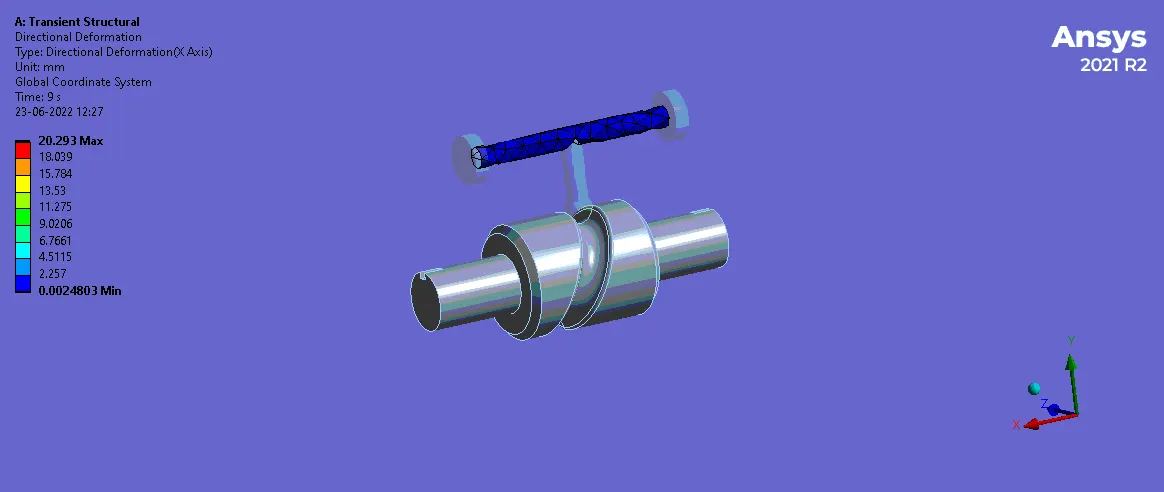
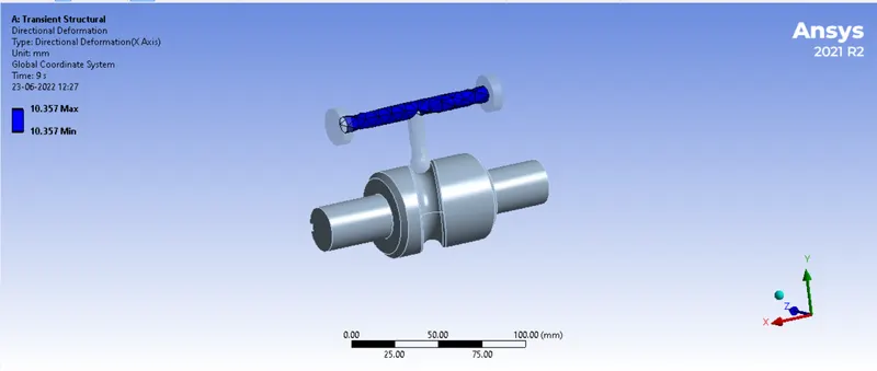
Directional deformation
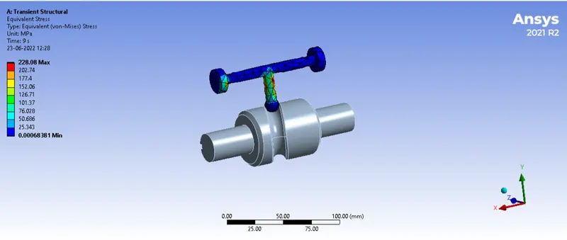
Equivalent stress:
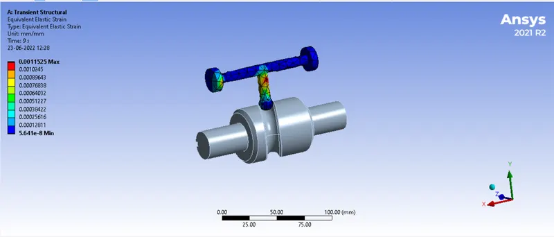
Equivalent strain
To obtain the results for frictional contacts, the above module was duplicated and the contacts were made frictional with the coefficient of 0.1. The coefficient of friction was parameterised and so were the outputs for maximum stress, strain and directional deformation. The parametric study was done. The results are presented below:
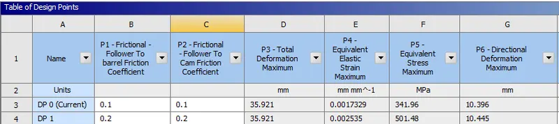
| Contact type | Max. equivalent strain | Max. equivalent stress (MPa) | Max. directional deformation (mm) |
| Frictionless | 0.0011525 | 228.08 | 10.357 |
Conclusion:
As can be seen from the results, the stress, strain and directional deformation, all increase with the increase in the coefficient of friction, because increased friction offers more resistence causing more strain and thereby more stress. The zip file is attached herewith.