Assignment 7-Side Pole Crash Simulation Challenge
Objective:
The objective of this challenge is to perform a side pole crash analysis of a vehicle against a rigid pole. The results to be obtained were the forces at given cross sections in different components, the intrusions of the given nodes and the velocity of a node on the door of the vehicle.
Case setup & execution:
First, the given solver deck “neon_side_reduced_0000.rad” was opened in Hypermesh.
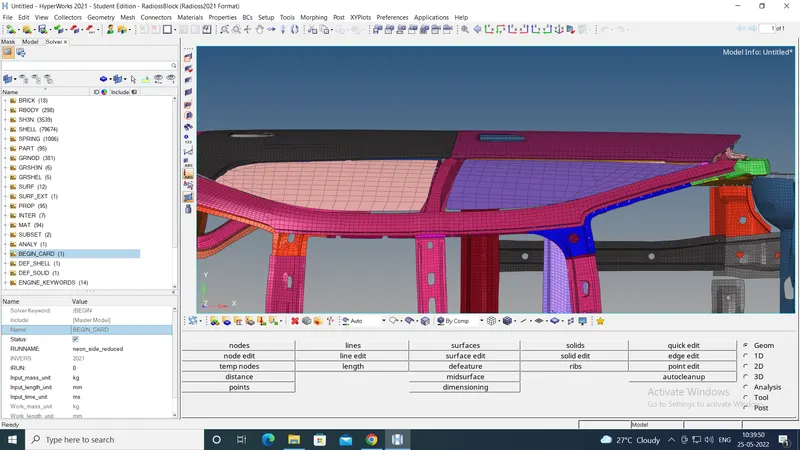
To check the unit system used in the file, the “BEGIN” card was opened from the solver browser. The unit system used was kg-mm-ms. This is shown in the image below:
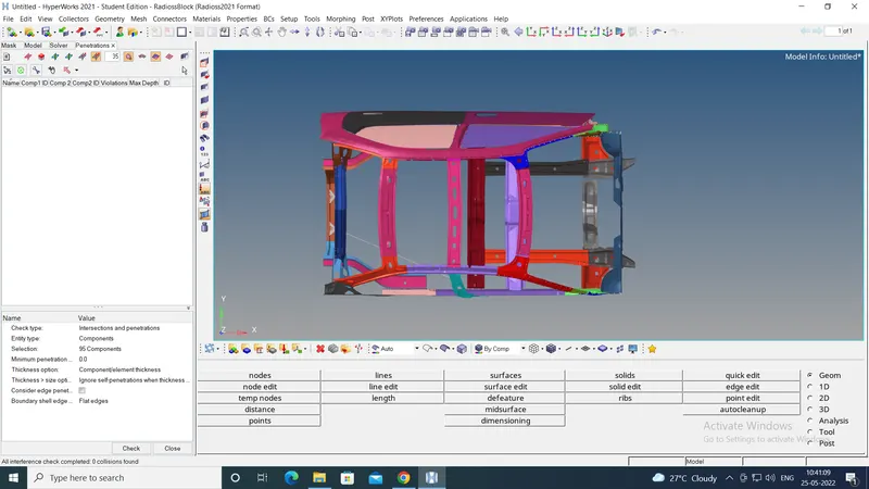
Then to check, if there were any initial penetrations, under "Tool" option from the menu bar, "Penetration check" option was used. It showed that there were no initial penetrations as below:
Then a Rigid pole was needed to be created. To create it, from "Tools" option on the menu bar, "create cards" option was chosen. Under it, "RWALL-CYL" option was selected. The base node of the Rigidwall was selected as a node on the B-pillar of the vehicle. The normal direction was selected as (-1,0,0). The Dsearch was input as 2000 mm ensuring nodes within this distance were slaves of the RWALL. The slide option was selected as 2. The co-efficient of friction was input as 0.1. The diameter of the cylindrical RWALL was input as 254mm or 10 inches as per the standard regulations.

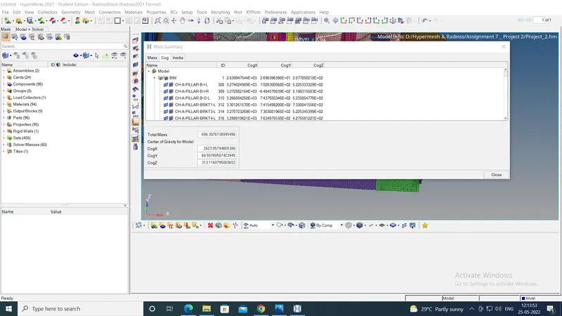
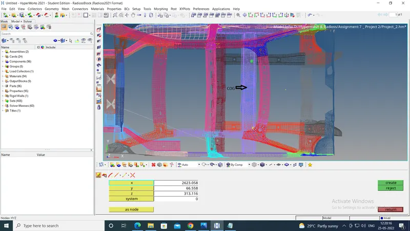
At this time, to bring the center of gravity (COG) of the vehicle closer to the ideal location, the masses needed to be added. To do this, "ADMAS" card was used. Under this, mass/node was added. The group of nodes was selected at 2 locations - driver and shoutgun - and 265 kg was added at each location. This increased the total mass of the system to almost 696 kg. This brought the COG closer to ideal location as shown below:
Now the vehicle was given the initial velocity. To do this, under "Tools" option in Menu bar, "Create cards" option was used. Under this "Boundary conditions" option was chosen, under which "INIVEL" option was chosen. The nodes on the vehicle were given a velocity of 20 mph i.e. 8.94 mm/ms. in positive Y-direction.
Then the end time of the run 80 ms was input using ENG-RUN card by using the "Tools" option on Menu bar. Under this, "create cards" - "Engine KEYWORDS" - "RUN" path was followed. Using the same "ENGINE Keyword" option, the size of nodal time step was input using "ENG/DT/NODA" option.
Then the self-contact of the vehicle body was to be defined. This was defined using type 7 contact. To do this the "Tools" option on Menu bar was used. Under this, "create cards" - "INTER" - "Type 7" path was followed.
To give the self-contact, the group of nodes of slave were selected as the nodes on the vehicle body. For master, all the components were selected. The following parameters were used to define the interface:
Istf = 4, Igap=3, Idel=1000, Fscale_gap=0.9, Stmin=1.0, Stfac=0.9, Fric=0.2, Gapmin=0.55, Inacti=6, Ifrom=2
To get the required outputs, the cross-sections were needed to be created at the given locations. To create the cross sections, following procedure was followed:
First, the local coordinate system (Frame) was created using "Create cards"-"FRAME" option. The "moving" frame was created to account for the motion of the vehicle. The points were selected such that, the z-axis pointed in the direction oppposite to the load travelling path.
After creating the "FRAME", "Create cards"-"SECT"-"SECT" option was used to create the cross section. The N1,N2,N3 were the same nodes selected to create the corresponding "FRAME", selected in the same order, so that the normal to the cross section is parallel to the z-axis of the "FRAME". Then the "Frame_ID" was given as the ID of the corresponding "FRAME". The deltaT=0.1 and alpha=1.65 were given.
But this created an infinite plane. To get the results in a particulat component, the cross section should be limited to that component only. To ensure this, the elements on both the sides of the plane and on the desired component only, were selected as part of a group under the "grshel_id".
This way, the cross sections were created at 2 locations - in front & rear cross members.
Now, the output blocks related to the created cross sections needed to be created. These were created by right clicking in model browser and selecting "Create"-"Output block" path. In each output blocks the corresponding cross sections were input.
The intrusion of nodes on the left rocker at 3 locations : at hinge pillar, B-pillar and fuel tank location were to be checked. To do this, from "SPRING" option in the solver browser, 2-noded springs were created, each connecting one of the above nodes to a node on the opposite rocker. These spring members formed a new component. Then a new property was created using properties card. The type of element was selected as spring and the individual spring elements created earlier were selected. The mass of 0.001 kg and stiffness of 0.001 kN/mm were input.
Now, the output blocks related to the created spring elements were needed to be created. These were created by right clicking in model browser and selecting "Create"-"Output block" path. In each output blocks the corresponding spring element was input.
This completed the setup of the model. Then under "Tools" "model checker" was used. It showed one error. To rectify this error, "auto correct" option was clicked. This removed the error. The model was ready to run.
To check whether the animation of the deformation was on expected lines, the model was run with high mass scaling. Hence the DT/NODA was changed to 0.005 ms. This finished the run in around 12 minutes and 34 seconds as shown below:
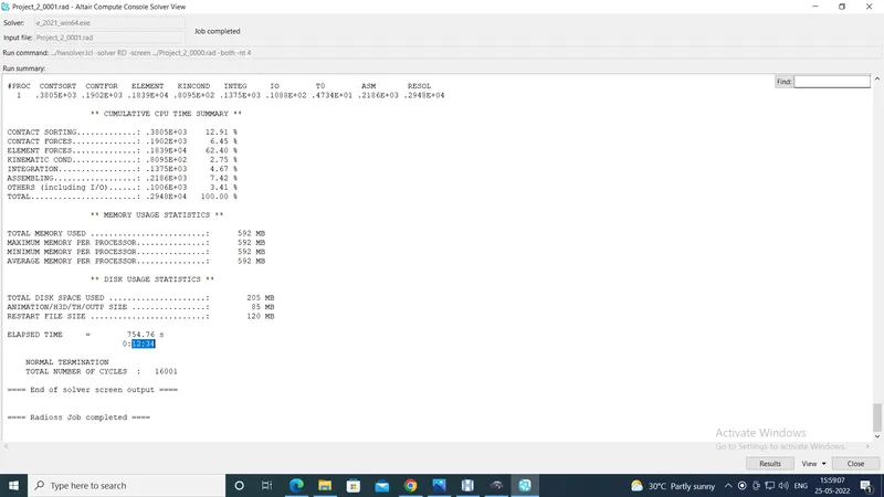
The animation showed the deformation on the expected lines.
Hence the final simulation was run using the DT/NODA value of 0.0005 ms. The simulation ran for about 2 hours and 3 minutes and there was normal termination.
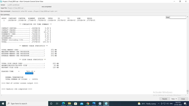
The results are shown below.
Results:
The energy error is -1.6% and the mass added is 4.3579e-3%. Both these values are in acceptable range.
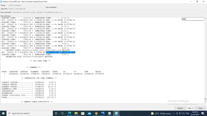
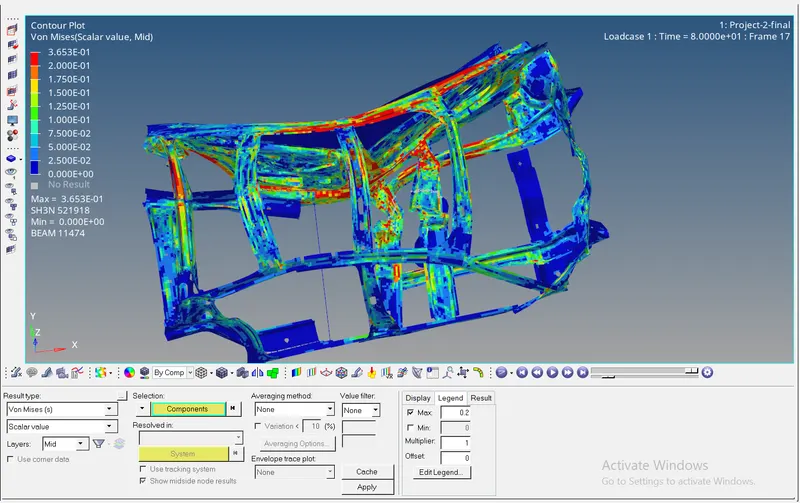
The von mises stresses generated are shown below:
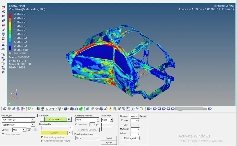
The maximum value of the von mises stress is 0.3653 kg/mm.ms2
The energy plots are shown below:
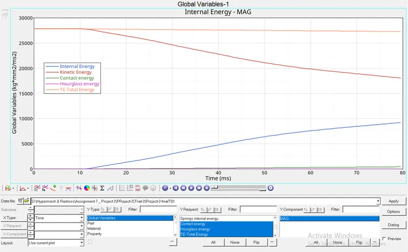
As can be seen, the total energy of the system is almost constant, which is acceptable. Also the kinetic energy is decreasing and the internal energy is increasing, indicating that the kinetic energy is being absrobed as the strain enrgy by the deformed components of the vehicle.
Also at the end of the run, total energy is about 27,000 units, while (contact energy+hourglass energy) is about 300 units. Thus (contact energy+hourglass energy) form around 1.11% of the total energy, which is also an acceptable result.
The results for the intrusion of the specified nodes are given below:
1. Intrusion of node at hinge pillar
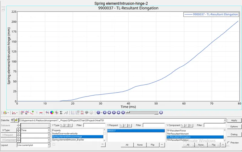
Thus the maximum intrusion of node at hinge pillar = 200 mm
2. Intrusion of node at B-pillar
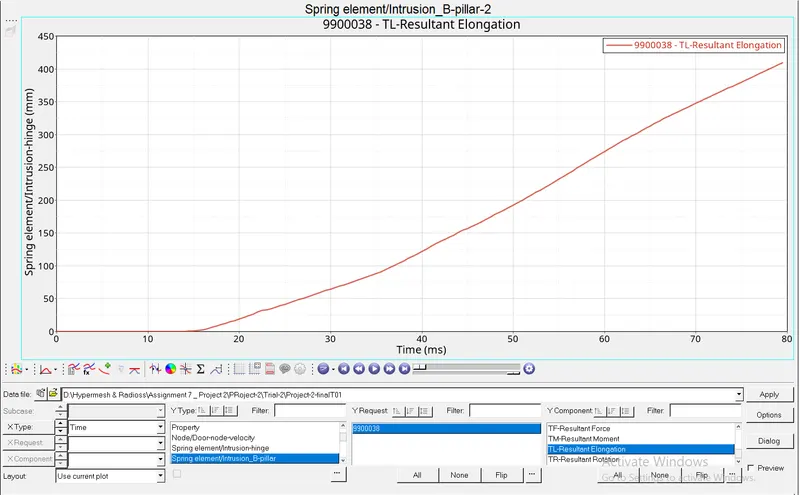
Thus the maximum intrusion of node at B-pillar = 410 mm
3. Intrusion of node near fuel tank location
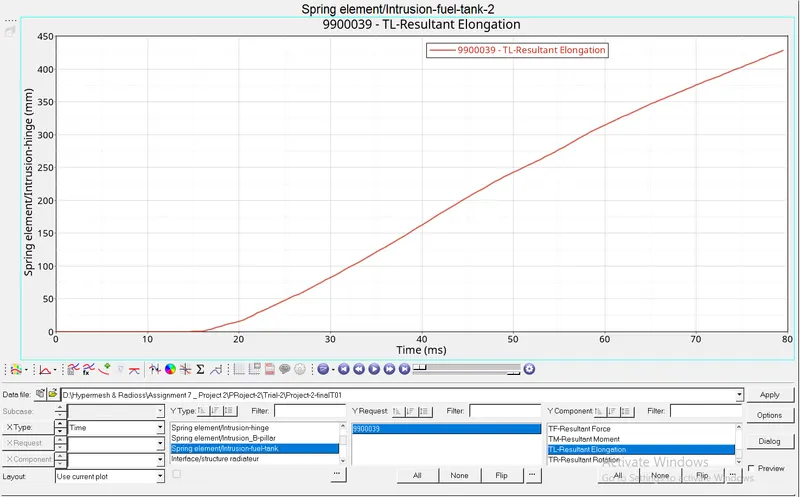
Thus the maximum intrusion of node near fuel tank location = 425 mm
The forces at the cross section in the front corss member are shown below:
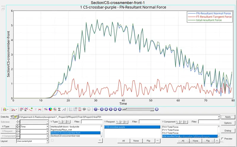
Thus the peak value of the resultant force in the section is about 5.4 kN, which is in the acceptable range, considering the yield strength of steel is 210 GPa.
The forces at the section in the rear cross member are:
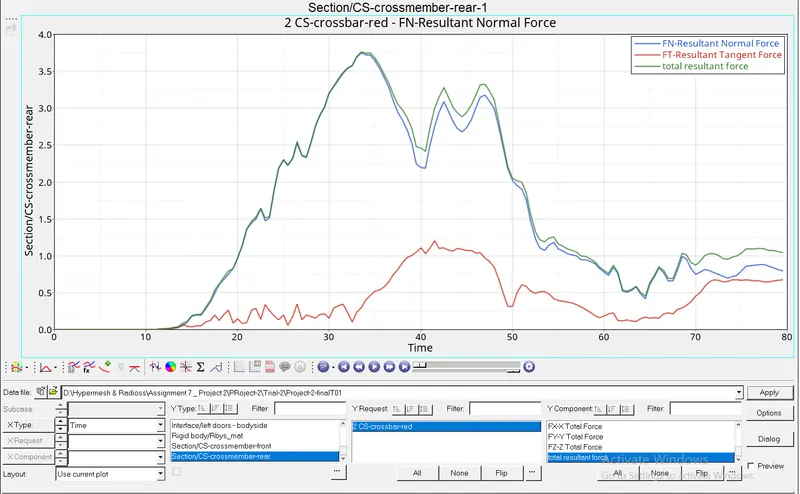
Thus the peak value of the resultant force in the section is about 3.75 kN.
The plot for the velocity of inner node on the door is:
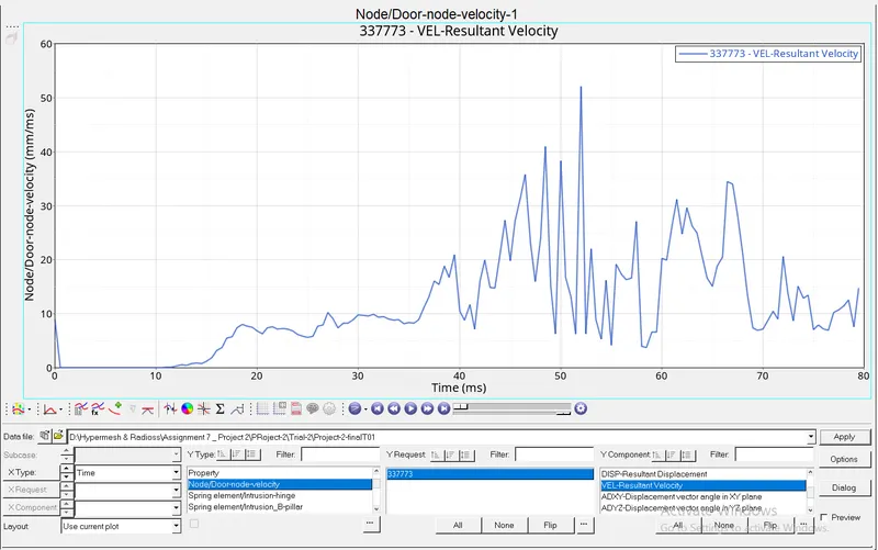
Thus the peak value of the resultant velocity of the inner node on the door is about 52 mm/ms.
| Peak resultant force in section in front cross member (kN) | 5.4 |
| Peak resultant force in section in rear cross member (kN) | 3.75 |
| Peak intrusion of node near hinge pillar (mm) | 200 |
| Peak intrusion of node near B-pillar (mm) | 410 |
| Peak intrusion of node near fuel tank location (mm) | 425 |
| Peak velocity of the inner node of the door (mm/ms) | 52 |
| Maximum von-mises stress (kg/mm.ms2) | 0.3653 |
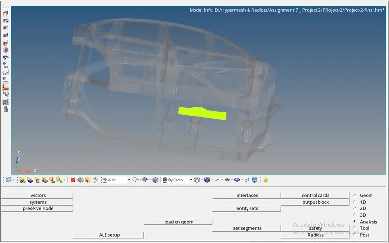
As can be seen, the sectional force in front cross member is more than that in the rear cross member, despite the rear cross member receiving much of the impact of the collision. This is because of the added mass of 265 kg at the driver location on the front cross member as shown in the image below. This signifies the importance of the passenger weight in the actual analysis.
 Recommendation to reduce intrusion at fuel tank location:
The intrusions at B-pillar and the fuel tank location are more than that at the hinge pillar. This is becuase the B-pillar receives the direct impact of the collision. As can be seen from the image below, the front cross member got compressed and reduced the intrusion of node at hinge pillar. Similarly, the intrusion near fuel tank location can be reduced by adding a cross member at that location.
Conclusion:
Thus, the simulation results are acceptable, considering the energy error and mass addition are very small. Also the kinetic energy is efficiently being converted to internal energy. The results are given in the above table. The project files are attached below in zip format.