Assignment 6-Frontal Crash Simulation Challenge
Objective:
The objective of this challenge is to perform a frontal crash analysis of a vehicle against a rigid wall. The results to be obtained were the forces at given cross sections in different components, the acceleration of rockers at B-pillars and the displacement of the given nodes on the dash wall.
Case setup & execution:
First, the given solver deck “neon_front_0000.rad” was opened in Hypermesh.
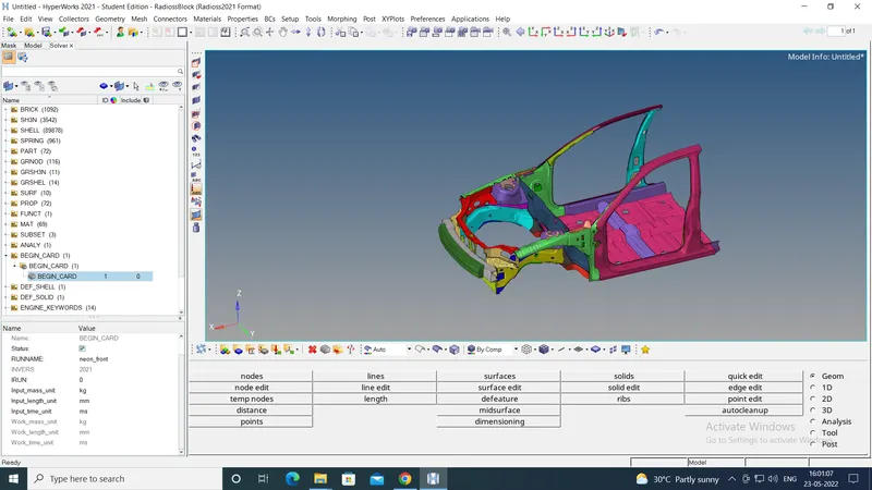
To check the unit system used in the file, the “BEGIN” card was opened from the solver browser. The unit system used was kg-mm-ms. This is shown in the image below:
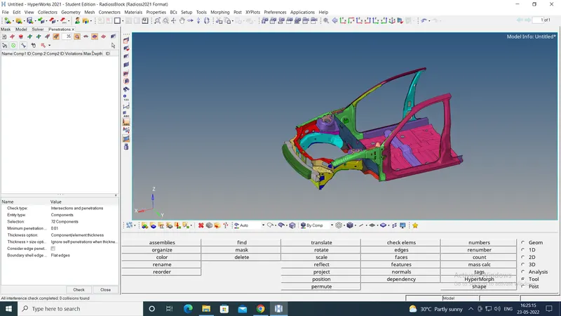
Then to check, if there were any initial penetrations, under "Tool" option from the menu bar, "Penetration check" option was used. It showed that there were no initial penetrations as below:
Then the Rigidwall was needed to be created. To create it, from "Tools" option on the menu bar, "create cards" option was chosen. Under it, "RWALL-PLANE" option was selected. The base node of the Rigidwall was to be selected as a node on the bumper of the vehicle. For this, from the "Geom" panel, "node" option was selected and the coordinates of the selected node were noted down as shown below:
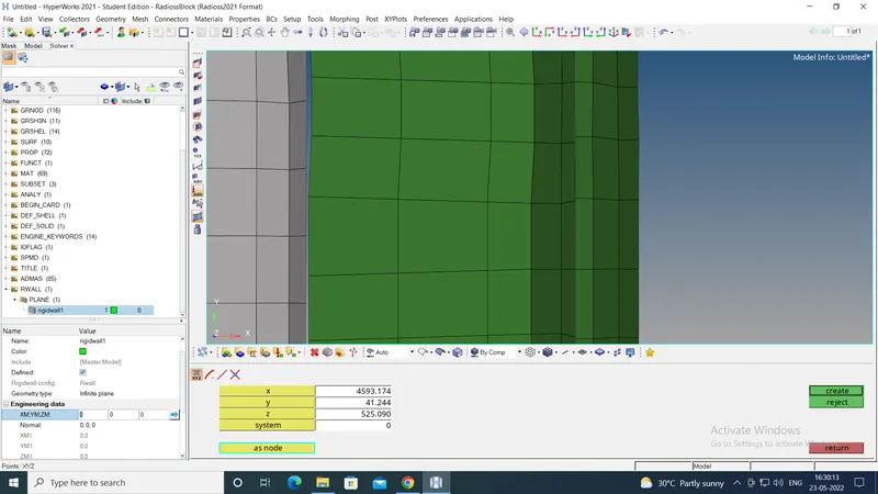
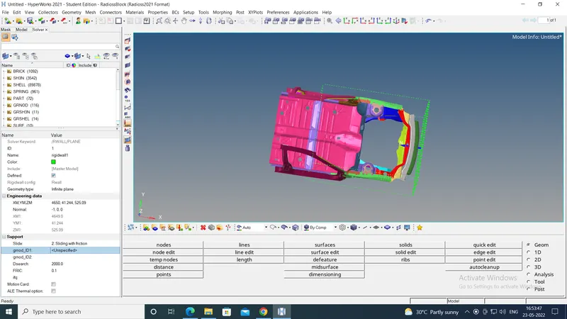
These coordinates were input as the base point of the RWALL. The normal direction was selected as (-1,0,0). The Dsearch was input as 2000 mm ensuring nodes within this distance were slaves of the RWALL. The slide option was selected as 2. The co-efficient of friction was input as 0.1.
At this time, the center of gravity (COG) of the vehicle was somewhere near the dashwall. To bring it closer to the ideal location, the masses needed to be added. To do this, "ADMAS" card was used. Under this, mass/node was added. The group of nodes was selected at four locations - driver, shoutgun, driver back and shotgun back - and 125 kg was added at each location. This increased the total mass of the system to almost 688 kg. This brought the COG closer to ideal location as shown below:
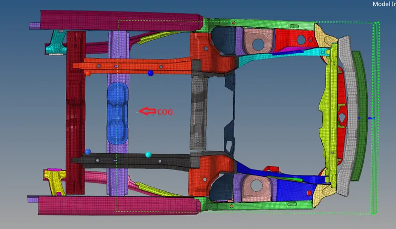
Now the vehicle was given the initial velocity. To do this, under "Tools" option in Menu bar, "Create cards" option was used. Under this "Boundary conditions" option was chosen, under which "INIVEL" option was chosen. The nodes on the vehicle were given a velocity of 35 mph i.e. 15.6 mm/ms. in positive x-direction.
Then the end time of the run 80 ms was input using ENG-RUN card by using the "Tools" option on Menu bar. Under this, "create cards" - "Engine KEYWORDS" - "RUN" path was followed. Using the same "ENGINE Keyword" option, the size of nodal time step was input using "ENG/DT/NODA" option.
Then the self-contact of the vehicle body was to be defined. This was defined using type 7 contact. To do this the "Tools" option on Menu bar was used. Under this, "create cards" - "INTER" - "Type 7" path was followed.
To give the self-contact, the group of nodes of slave were selected as the nodes on the vehicle body. For master, all the 72 components were selected. The following parameters were used to define the interface:
Istf = 4, Igap=3, Idel=1000, Fscale_gap=0.9, Stmin=1.0, Stfac=0.9, Fric=0.2, Gapmin=0.55, Inacti=6, Ifrom=2
To get the required outputs, the cross-sections were needed to be created at the given locations. To create the cross sections, following procedure was followed:
First, the local coordinate system (Frame) was created using "Create cards"-"FRAME" option. The "moving" frame was created to account for the motion of the vehicle. The points were selected such that, the z-axis pointed in the direction oppposite to the load travelling path.
After creating the "FRAME", "Create cards"-"SECT"-"SECT" option was used to create the cross section. The N1,N2,N3 were the same nodes selected to create the corresponding "FRAME", selected in the same order, so that the normal to the cross section is parallel to the z-axis of the "FRAME". Then the "Frame_ID" was given as the ID of the corresponding "FRAME". The deltaT=0.1 and alpha=1.65 were given.
But this created an infinite plane. To get the results in a particulat component, the cross section should be limited to that component only. To ensure this, the elements on both the sides of the plane and on the desired component only, were selected as part of a group under the "grshel_id".
This way, the cross sections were created at 8 locations - in right & left rail, right & left rail of bumper, right & left bottom rail, and right & left A-pillars.
Also the accelerometers needed to be created near the 2 B-pillars. To do this, first the local skew was created at the desired locations. Then "Create cards"-"ACCEL" path was used to create the accelerometers. The desired nodes at the B-pillars and the corresponding skew ID were selected to create the accelerometer.
Now, the output blocks related to the created cross sections and accelerometers needed to be created. These were created by right clicking in model browser and selecting "Create"-"Output block" path. In each output blocks the corresponding cross sections and accelerometers were input.
To create output block for intrusion of nodes on dash wall, first the local skews were created with origins on the bottom floor of the vehicle. Then a new output block was created, in which the node on the dashwall was input and the corresponding skew was selected.
This completed the setup of the model. Then under "Tools" "model checker" was used. It showed no errors. The model was ready to run.
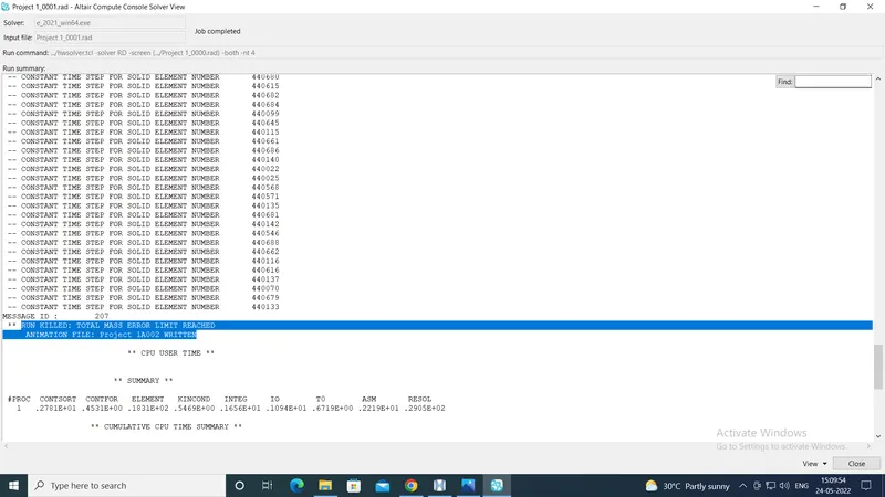
To check whether the animation of the deformation was on expected lines, the model was run with high mass scaling. For this DT/NODA was input as 0.05 ms. But this killed the simulation run due to very high mass addition as shown below:
Hence the DT/NODA was changed to 0.005 ms. This finished the run in around 13 minutes as shown below:
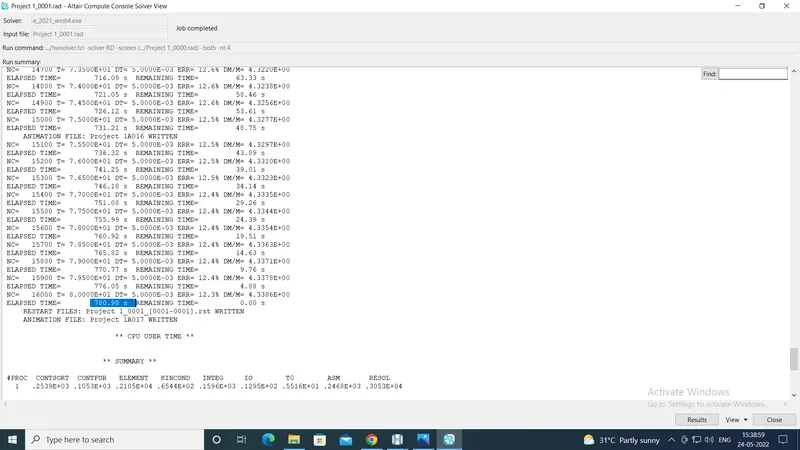
The animation showed the deformation on the expected lines.
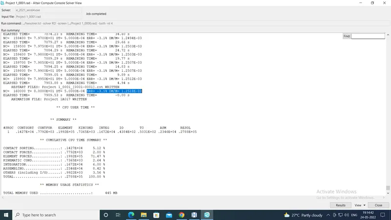
Hence the final simulation was run using the DT/NODA value of 0.0005 ms. THe simulation ran for about 2 hours and 11 minutes and there was normal termination.
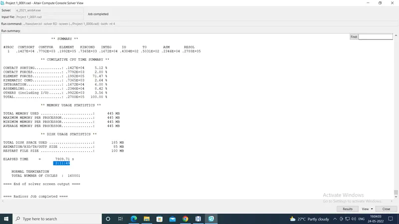
The results are shown below.
Results:
The energy error is -3.1% and the mass added is 0.125%. Both these values are in acceptable range.
The von mises stresses generated are shown below:
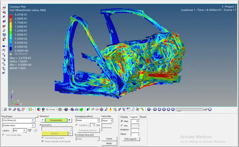
The maximum value of the von mises stress is 0.3475 kg/mm.ms2.
The energy plots are shown below:
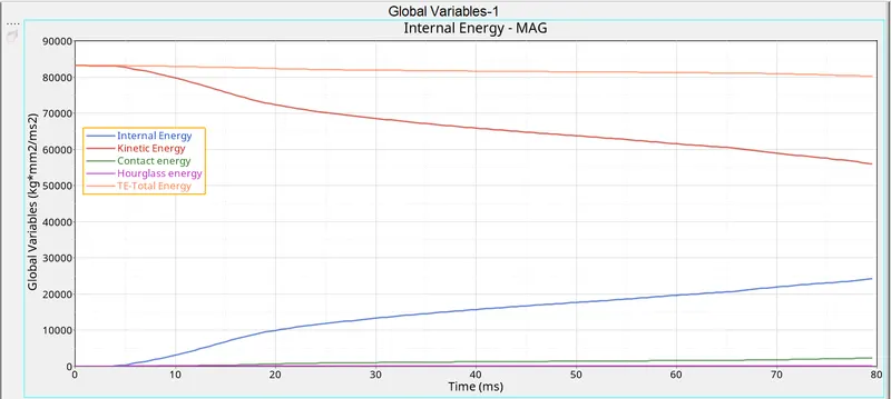
As can be seen, the total energy of the system is almost constant, which is acceptable. Also the kinetic energy is decreasing and the internal energy is increasing, indicating that the kinetic energy is being absrobed as the strain enrgy by the deformed components of the vehicle.
Also at the end of the run, total energy is about 80,000 units, while (contact energy+hourglass energy) is about 1,000 units. Thus (contact energy+hourglass energy) form around 1.25% of the total energy, which is also an acceptable result.
The results for the intrusion of the specified nodes are given below:
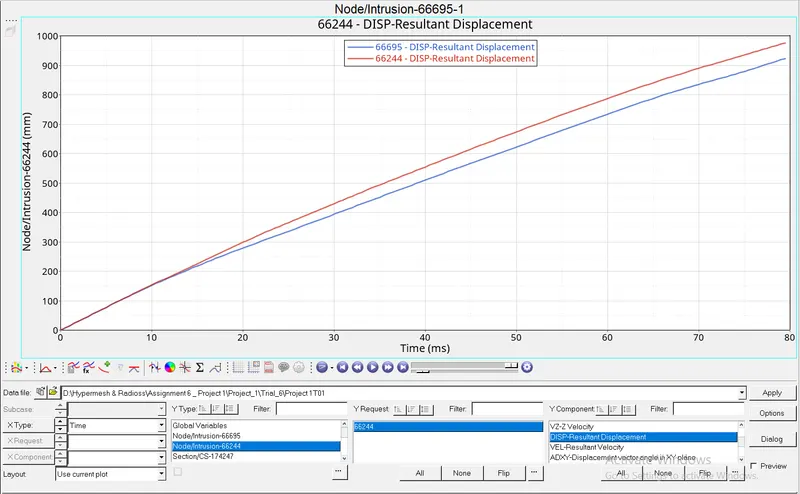
Thus the maximum intrusion of node 66695 = 910 mm
The maximum intrusion of node 66244 = 990 mm
Thus the intrusion is more on the right hand side portion of the vehicle, looking from the driver's point of view, which is also discernible in the animation file and the von-mises stress plot attached above.
The forces at the cross section at the node 174247 in the left rail are shown below:
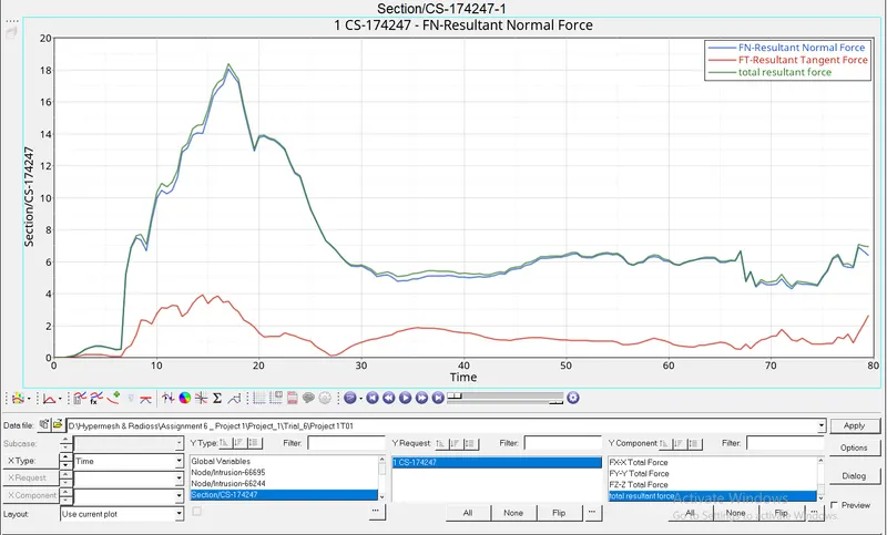
Thus the peak value of the resultant force in the section is about 18.4 kN, which is in the acceptable range, considering the yield strength of steel is 210 GPa.
The forces at the section in the right rail are:
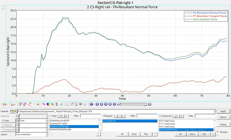
The forces in section at right A-pillar are :
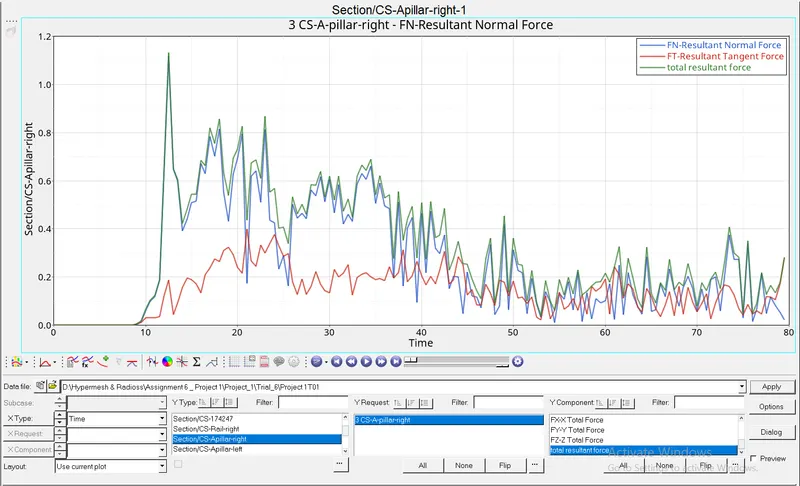
Left A-pillar:
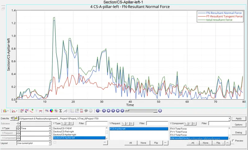
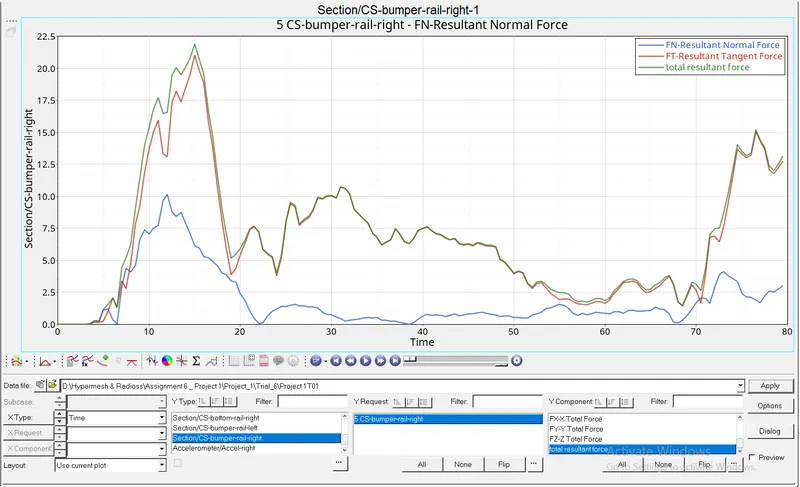
Right rail of the bumper:
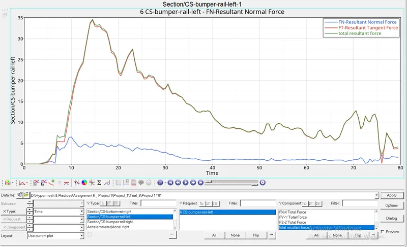
Left rail of the bumper:
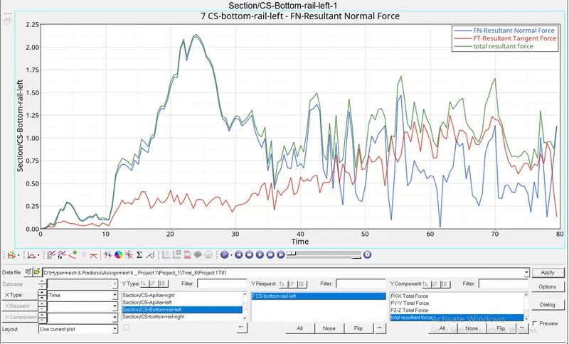
Left bottom rail:
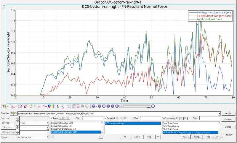
Right bottom rail:
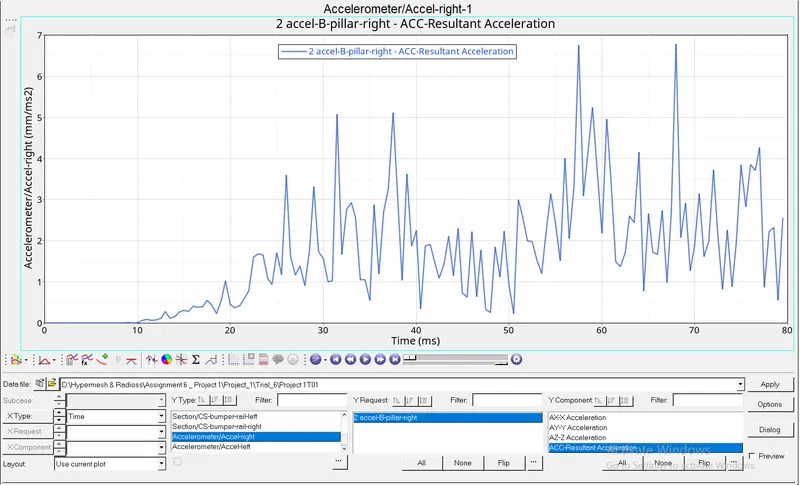
Acceleration of a node on right B-pillar:
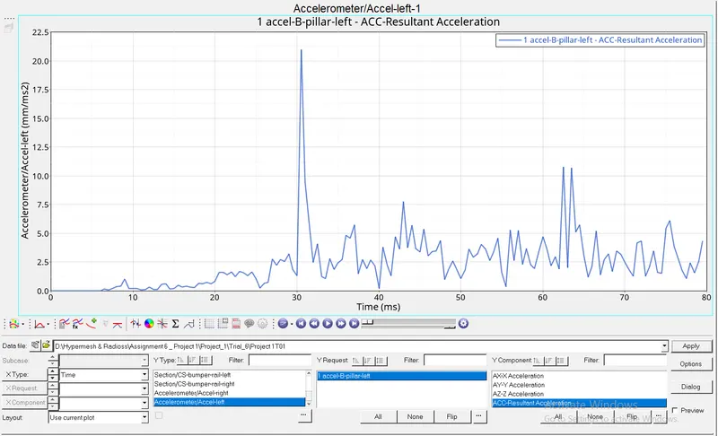
Acceleration of a node on left B-pillar:
Thus,
| Peak resultant force in section at node 174247 (kN) | 18.4 |
| Peak resultant force in section in right rail (kN) | 23 |
| Peak resultant force in section in left A-pillar (kN) | 1.3 |
| Peak resultant force in section in right A-pillar (kN) | 1.35 |
| Peak axial force in section in left rail of bumper (KN) | 6.5 |
| Peak axial force in section in right rail of bumper (KN) | 10 |
| Peak resultant force in shot gun cross section on left (kN) | 2.1 |
| Peak resultant force in shot gun cross section on right (kN) | 1.5 |
| Peak resultant acceleration in left B-pillar (mm/ms2) | 21 |
| Peak resultant acceleration in right B-pillar (mm/ms2) | 6.8 |
| Peak intrusion of dash wall node 66695 (mm) | 910 mm |
| Peak intrusion of dash wall node 66244 (mm) | 990 mm |
| Maximum von-mises stress (kg/mm.ms2) | 0.3475 (=0.3475 GPa) |
Conclusion:
Thus, the simulation results are acceptable, considering the energy error and mass addition are very small. Also the kinetic energy is efficiently being converted to internal energy. The results are given in the above table. The project files are attached below in zip format.