Bird Strike - Project - 2
Aim:
The aim of this project is to simulate the situation in which a bird strikes in the turbine blades of an aeroplane. The project aims to test one's complete understanding of the LS-Dyna software. The aim is to create the model file, which references to all the input files to match the working standards in a professional environment. Also the aim was to use the renumbering techniques similar to an industrial environment. The teqchniques like mass scaling were also expected to be used. Finally, the results of the simulation are to be presented and discussed.
Explanation:
For the project, 2 .k files were provided. The first one was the Bird_strike model and the other was the material model for the blades.
First, from the Bird_strike model, the individual parts were separated into separate .k files. The model had 4 parts, out of which 3 parts were deleted and the remaining part was saved. This procedure was repeated for each part. Thus 4 separate part files called Bird.k, Casing.k, Hub.k and Blades.k were obtained.
Then the renumbering was done, in which parts were numbered in series of 1000+, nodes in 100000+ and elements in 500000+. The section files had 10000+, material files had 11000+, node sets as 12000+, contact cards had 13000+ and part sets had 17000+ numbering system. The numbering system is explained below:
Renumbering / ID system
Parts: Casing = 1001 Blades = 1002 Hub = 1003 Bird = 1004
Section: Shell section = 10001
Solid section = 10002
Material: Aluminium = 11001
Steel = 11002
Bird = 11003
Node set ID: Casing (spc) = 12001
Contact cards: Aut_surf_to_surf (blades_bird) = 13001
Tied_nodes_surface (hub-blades) = 13002
Part set ID: hub_blades = 17001
|
Casing (1001) |
Blades (1002) |
Hub (1003) |
Bird (1004) |
|
|
Nodes |
100001 - 104097 |
105001 - 111259 |
112001 - 115988 |
116001 - 116418 |
|
Elements |
500001 - 503968 |
504001 - 509473 |
510001 - 530844 |
531001 - 531410 |
|
Section |
10001 |
10001 |
10002 |
10001 |
|
Material |
11002 |
11001 |
11002 |
11003 |
Then a part set of Hub and blades was created as the Hub_blades.k file by including the Hub.k and Blades.k files.
Then the Casing.k file was opened and node set of all the nodes of the casing was created in the same file.
Then the given material model for blades was opened. In this the materials for the bird, the casing and the hub were defined and it was saved as a separate .k file called Material_file.k.
From the Young's modulii given for the materials for bird and casing in the question, it was decided that, the material for bird would be ABS plastic and for the casing & hub, it would be steel. For both the bird and the casing, the elastic material card MAT_001 Elastic was used, as per the question. The corresponding material properties are shown below. The Kg-mm-ms unit system has been used.
For steel: MAT_001 Elastic Density = 7.8e-6 kg/mm3 E = 200 kg/mm.ms2 PR = 0.3
For ABS plastic: Density = 1.1e-6 kg/mm3 E = 2 kg/mm.ms2 PR = 0.3 SIGY = 0.035 kg/mm.ms2
For blades the material model included the elasto-plastic material as Aluminium with following properties:
Density = 2.71e-6 kg/mm3 E = 68.948 kg/mm.ms2 PR = 0.33 SIGY = 0.013362 kg/mm.ms2 Failure strength = 0.2723kg/mm.ms2
The material properties for ABS plastic were sourced from following sources:
https://www.bestech.com.au/wp-content/uploads/Modulus-of-Elasticity.pdf
https://omnexus.specialchem.com/polymer-properties/properties/density
https://omnexus.specialchem.com/selection-guide/acrylonitrile-butadiene-styrene-abs-plastic
As given in the question, it was decided to use elastic material for the bird. The materials were allotted by providing the respective Part Id numbers.
After this, Section_file.k was created, which contained the sections alloted to the parts. The shell section was allotted to the bird, casing and the blades. A solid section was allotted to the hub. The sections were allotted by providing the respective Part Id numbers.
After this the files for the boundary conditions were created. The SPC was provided to the node set of the nodes of the Casing.
Initial velocity generation keyword was used to provide initial velocity to the bird and the initial rotational velocity of 0.0524 rad/ms (=500 rpm) to the hub and blades. This was done by providing the rotating velocity to the hub and changing the IVATN value to 1. IVATN=1 ensures the velocity given to the master part is also given to the connected slave parts. The card is shown below: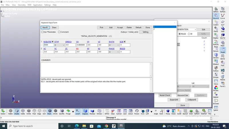
The bird was provided the velocity of 30 mm/ms in the positive x-direction.
Then the contacts were defined using Contact_file.k file. The file defined the automatic surface to surface contact between the bird and the blades with blades as master and bird as slave.
After this the control conditions were created. The houglass was included to avoid hourglassing of shell elements. The termination time was provided as 15 ms. Control_timestep was also included to control dt2ms and mass scaling.
Finally, the output requests were provided by creating database cards. These included ASCII option for GLSTAT, MATSUM and NODOUT to check the total energy, the energy of individual parts and properties of selected nodes respectively.
The Database_history_node was provided to check properties of one node each on the bird and the blades.
The d3plot was also requested. The Database_extent_binary with STRFLG=1 was also rquested to get the strain tensor output data.
Then a new file called Main.k was created. Using *INCLUDE_INCLUDE keyword, all the input files of parts, part sets, material, section, boundary conditions, contact, control parameters and database requests were included in the Main.k file. Then the file was saved and closed. To save the file "Save as - Save keyword as" option was used. In this the other .k files were toggled unchecked and only the Main.k file was checked and saved.
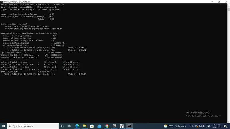
Then the Main.k file was opened in PrePost and the model was run without mass scaling. But only the total run time was checked. Without the mass scaling the total run time was 14 hours 35 minutes. The timestep size was 6.14e-05 ms. The screenshot is attached below. Then the run was killed.
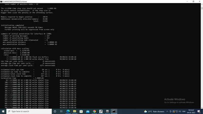
Then different trials with different dt2ms values were run. Finally in the trial 7, the run time was reduced to 5 mins due to the dt2ms of 1e-02 ms. The screenshot is attached below:
This time the model run was allowed to finish to check the final results to see whether it was running correctly. It ran smoothly with normal termination. But the d3plot showed that only the hub was rotating, but the blades were stationary.
To rectify this, CONTACT_TIED_NODES_TO_SURFACE was provided with the hub as the master and blades as the slaves.
But this time, instead of rotating along with the hub, the blades were getting twisted.
So instead of putting IVATN value as 1 in Initial velocity generation card, it is set to 0. Instead the part set of blades and hub is provided the rotating velocity in the Initial velocity generation card. The part set of hub & blades was provided the rotational velocity of 0.0524 rad/ms. This is equal to 500 rpm.
The model was run. But it showed 2 errors. First error said that nodes are duplicated. The second error said that the part ID 1003 was repeated. These are shown below:
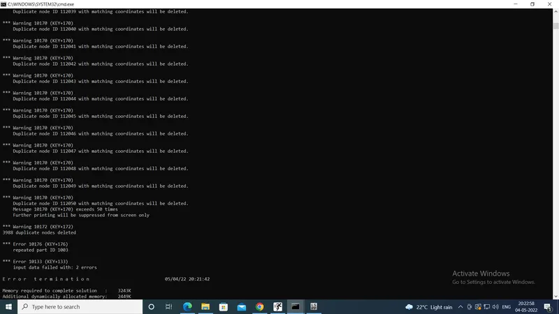
Hence in the part files Hub.k, Bird.k and Blades.k, the node sets created earlier were deleted, except for the Casing.k. Also the assembly was deleted completely and new Main.k file was created by Including all the input files. Then the model was run again.
This time the model ran smoothly with no errors. But the d3plot showed that the bird part was only getting collided with the blades and rotating with them, instead of passing through. This was due to low velocity of 5 mm/ms of the bird. Hence the velocity of the bird was increased to 30 mm/ms and the model was run.
After this, the model was run. The d3plot this time, showed the correct scenario, with the destruction of the bird part as well as the effective plastic strain.
Now that it was clear that the model was running correctly, the dt2ms was adjusted so that the mass scaling ratio remains less than or equal to 8%.
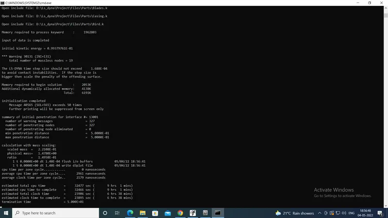
From the earlier trials, it was found that for dt2ms = 1.4e-04 ms, the mass scaling ratio was 14.95 % as shown below:
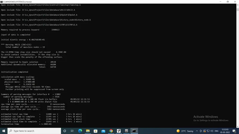
Hence now, the dt2ms = 1.1e-04 ms was input. But this led to a mass scaling ratio of 9.23 %.
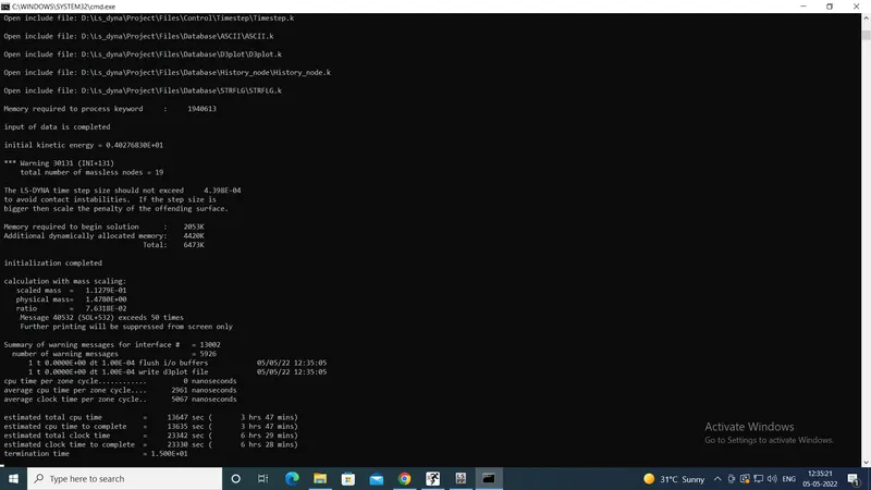
Hence dt2ms = 1.0e-04 ms was input now. This led to a mass scaling ratio of 7.63%, which is within the acceptable range of 8%. Hence this was given as the final dt2ms value.
The model was run. However the model was taking an unusually long time to solve. Despite starting the run at 12:35 PM, it was stuck at the same place till 8 PM. Hence the run was killed manually.
Later the dt2ms was changed to 1.6e-04 ms. This led to mass scaling ratio of 19.53% as shown below:
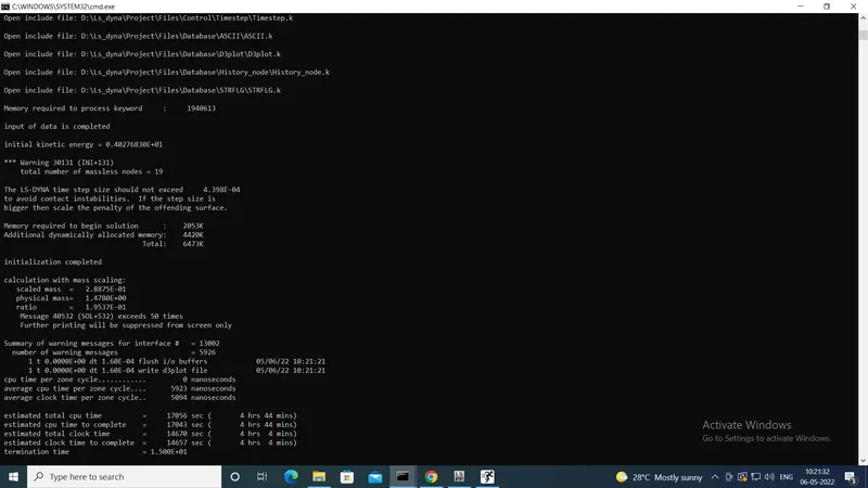
This model finished the run in 1.5 hours. The results were saved.
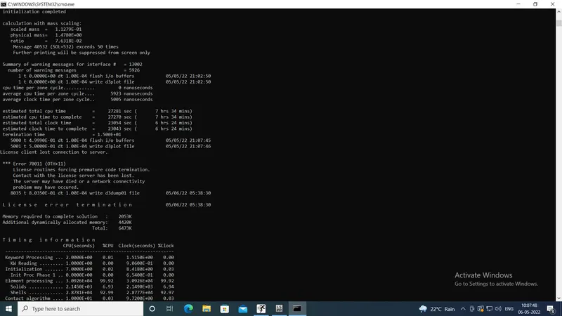
However at 9 PM again, the model with dt2ms=1.0e-04 ms with mass scaling ratio of 7.63% was run again and was allowed to run overnight. However, it was stuck at the same place i.e. after writing 2 steps of the d3plot, even at 5:38 AM in the next morning. This can be seen from following image:
Due to this problem, it was decided to consider the results of the simulation with dt2ms=1.6e-04 ms. The same are provided below:
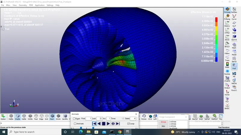
1. Effective or von mises stresses
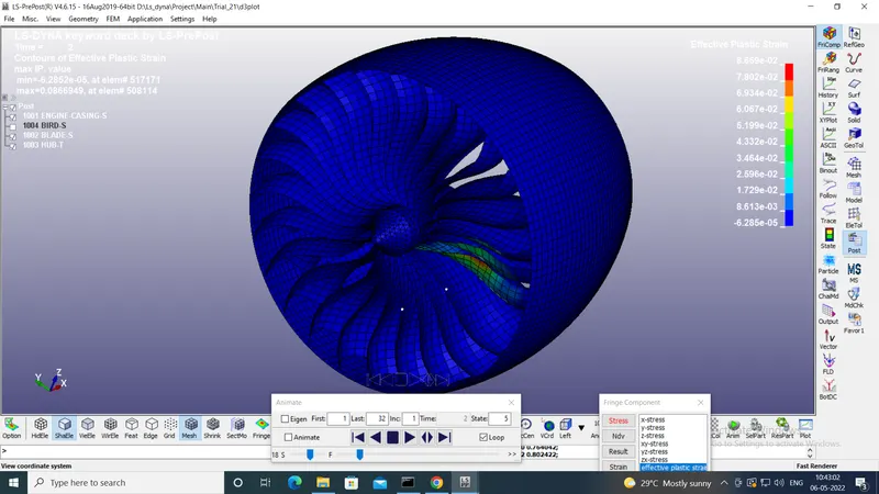
2. Effective plastic strain
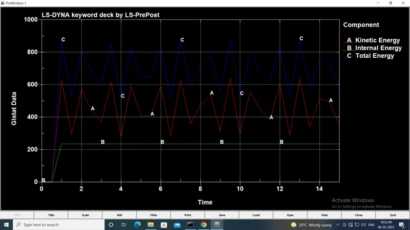
3. Energy plots:
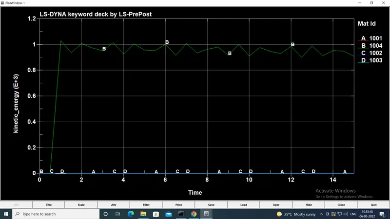
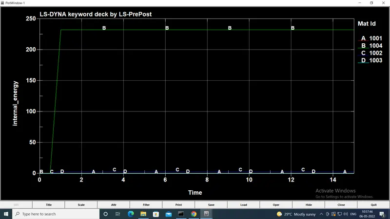
4. Matsum plots (energies of individual parts)
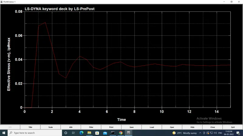
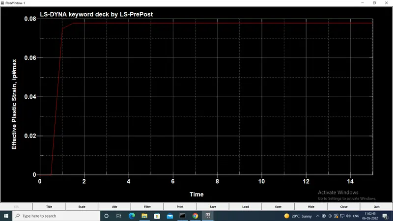
Similarly the time-history of v-m stress and effective plastic strain of an element ID 508117 on the blades, where bird impact is happening, were checked. They are provided below:
Conclusion:
Thus the results can be summed up in the following table:
For the blades:
| Max. von mises stress | 7.116 e-02 kg/mm.ms2 |
| Max. effective plastic strain | 8.669 e-02 (=8.669 %) |
It can be seen that the Kinetic energy and the total energy increase initially due to the initial velocity. They both decrease at somewhere around 4 ms, when the bird crashes into the blades. It can be observed that the kinetic energy controls the total energy of the system.
Also the time history plots of the element on the blades show the increase in stress and strain at the instance of crash. After this, the stress decreases and the strain remains unchanged.
Also the MATSUM plots show that the bird part has the maximum kinetic energy. This is obvious, because of the high velocity of the bird, because it is getting sucked into the turbine.
Thus the project was a good learning experience about a complete transient dynamic simulation in LS-Dyna. Also it provided lessons on the best industrial practices in terms of organising the files and using the INCLUDE keyword as well as renumbering standards. Thus the project imvolved the use of the entire learning of the course.
The files used in the project are attached as a zip file with the report. The animation as a GIF file is also attached.