Week 4 -Wire Bending Challenge
Objective:
The aim of this challenge is to simulate the wire bending operation and find out the equivalent stresses and strains generated in the wire.
Case setup and execution:
First the Static structural module was opened in Ansys Workbench. In the engineering data, from the general non-linear materials, copper alloy NL, Aluminium alloy NL and Magnesium alloy NL were added to the material library.
Then the geometrical model provided in the question was imported.
Then the model tab was opened. In the geometry tab from the model tree, the components were renamed. Also the wire was assigned the coppper alloy NL material.
Then in the Connections tab, the 2 existing contacts - one between the wheel & wire and the other between wheel and lever - were deleted.
The third contact - between the lever & wire - was duplicated and the contact-target pair was flipped.
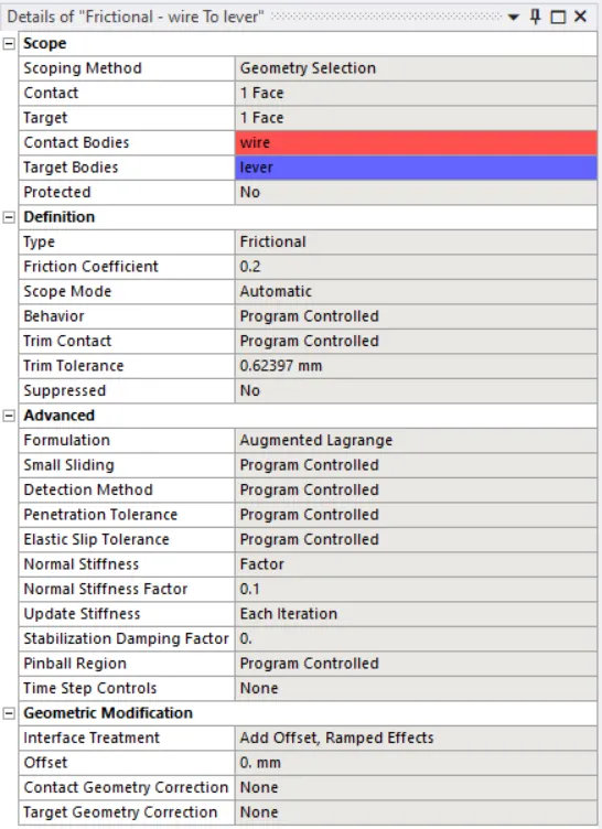
Both the contacts were made frictional with the coefficient of friction of 0.2. The Augmented Lagrange formulation was used. The behaviour was kept program controlled. The normal stiffness factor of 0.1 was used. The stiffness was updated in each iteration. The interface treatment was kept as "Add offset, ramped effects."
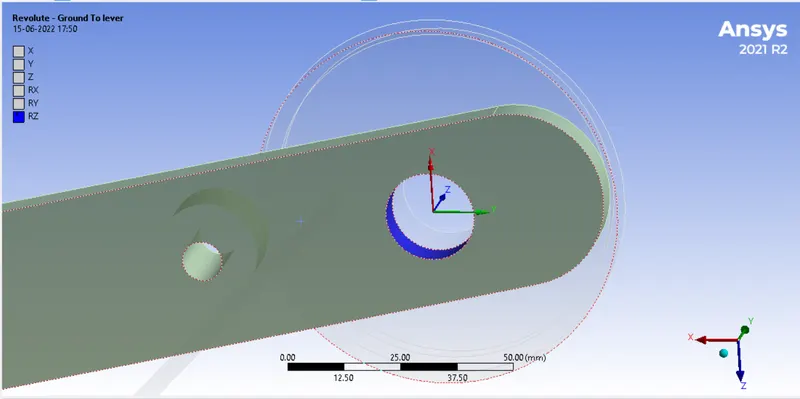
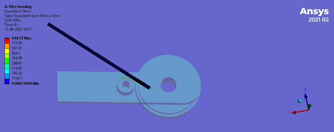
Then a new revolute joint was inserted as "body-to-ground" joint. The inner face of the circular hole on the lever was selected. The co-ordinate was aligned like it is shown in the below image:
Then the model was meshed with default mesh size. The mesh method was used to select the tetrahedron elements for the mesh. Then the face sizing was provided to the surface of the wire, the outer surface of the hole on the lever and the bend on the wheel. The face sizing of 2.2 mm was given.
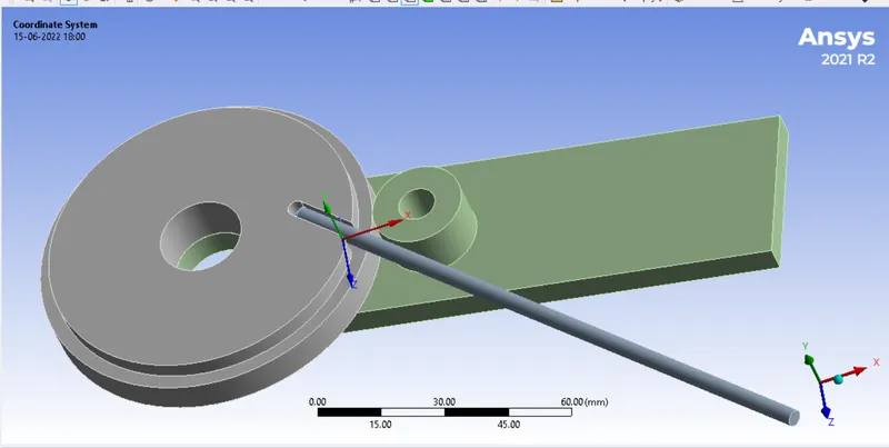
Then the segment of the wire close to the bend of the wheel was needed to be meshed with finer mesh. To do this, first a new coordinate system was created by right clicking on the bend surface. Then X-offset and Z-offset were selected. In X-direction, the offset of 3 mm was given and in z-direction, the offset of -3 mm was given.
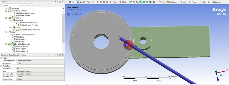
Then mesh-sizing was inserted. The element types were selected as "by sphere of influence" and the newly created coordinate system was chosen for the center of sphere. The radius of the sphere was 7 mm. The face of the wire was selected. The size of the elements was given as 0.8 mm.
In the analysis settings, 8 number of loadsteps were chosen. For the 1st loadstep, the initial timstep was given as 0.1 sec, minimum timestep was given as 0.01 sec and the maximum timestep was given as 0.2 sec. For rest of the steps, carry over timestep was turned on, minimum timestep was given as 0.01 sec and maximum timestep was given as 1 sec.
For all the loadsteps, the large deflection was turned on, the solver type was chosen as Direct and in Output controls, all the options were changed to "Yes".
Then a fixed support was provided at the innner circular face of the wheel. Another fixed support was provided to the circular cross sectional face at the fixed end of the wire.
Then a joint-load for rotation was inserted for the revolute joint provided to the lever. The rotation was applied in 8 loadsteps of -20 degrees each. The 7th and 8th loadstep had same value of -140 degrees rotation.
In the solution, the output was requested for equivalent stress and strain in the wire alone.
The model was run. But it failed to converge.
Hence following modifications were made in the setup:
1. The body sizing of 2 mm was provided to the wire.
2. The duplicated and flipped contact between wire and lever was deleted and a new contact was provided between the wire and the wheel's surface which are in contact.
3. The default mesh size was reduced to 5mm.
4. The face sizing of the face of lever, wire and bend on the wheel was reduced to 1.5 mm.
5. Weak springs in the analysis settings was turned on.
6. In the non-linear controls, stabilization was turned on and constant option was used. Energy method was used with the stabilization force limit of 0.1.
Then the model was run. This time it converged. The results are given below.
Results:
Animation
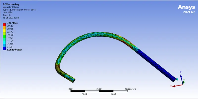
Equivalent stress in the wire
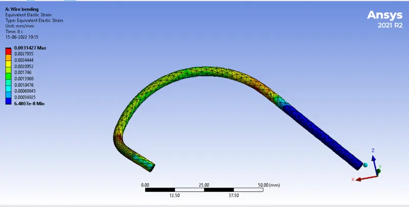
Equivalent strain in the wire
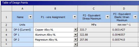
Since the material of the wire and the maximum values of the outputs were paprameterised, the parametric study was done to check the results for different materials, which are provided in following table:
Explanation of the results:
The copper alloy has the maximum Young's modulus (110 GPa), than Aluminum alloy (71 GPa) and Magnesium alloy (45 GPa). As a result, the strains generated are maximum in the magnesium alloy and the stresses generated are maximum in copper alloy.
Conclusion:
Thus the comparative study of the 3 materials has revealed the impact of the material properties on the results. While stress is maximum for copper alloy, it is minimum for the magenesium alloy. Aluminium alloy lies in between the two. But the pattern is reversed in case of strains. This is due to different Young's modulii of the materials.