Week 9 Tension and Torsion test challenge
AIM: To perform Explicit Dynamic Analysis for tension and torsion test.
OBJECTIVE:
To perform the tension and torsion test on the Given specimen.
- CASE: 1 For the tension test, to displace one end of the specimen to 18mm while keeping the other fixed.
- CASE: 2 For the torsion test, to displace one end of the specimen to an angle of 1200 degree.
THEORY:
Tension Test
- A tension test is a type of mechanical test used to determine the behaviour of materials under tensile loading. The test involves applying a gradually increasing tensile force to a sample of the material until it breaks or fractures.
- During the test, the sample is placed in a testing machine that can measure the amount of force applied and the corresponding elongation or deformation of the material. The data obtained from the test can be used to determine various properties of the material, such as its ultimate tensile strength, yield strength, ductility, and toughness.
- Tension tests are commonly used in engineering and materials science to evaluate the suitability of materials for specific applications. They can also be used to compare the properties of different materials and to assess the effects of manufacturing processes on material properties.
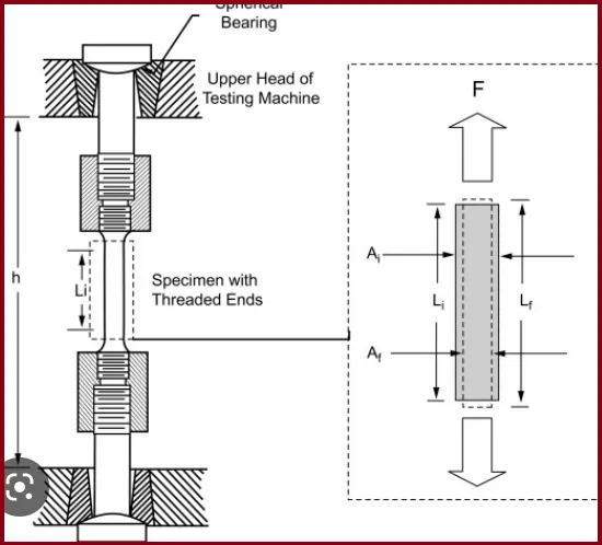
Torsion Test
- A torsion test is a type of mechanical test used to determine the behaviour of materials under torsional or twisting loading. The test involves applying a gradually increasing torque or twisting moment to a cylindrical or rectangular specimen of the material until it fractures.
- During the test, the specimen is clamped at one end and a torsional force is applied to the other end. The testing machine measures the amount of torque applied and the corresponding angle of twist of the specimen. The data obtained from the test can be used to determine various properties of the material, such as its shear strength, modulus of elasticity in shear, and ductility.
- Torsion tests are commonly used in engineering and materials science to evaluate the suitability of materials for specific applications that involve torsional loading, such as shafts, springs, and gears. They can also be used to compare the properties of different materials and to assess the effects of manufacturing processes on material properties.
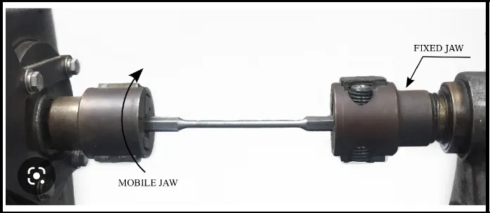
Explicit Analysis
Explicit analysis is a numerical simulation technique used in engineering and computational mechanics to model and analyse the behaviour of materials and structures under dynamic and transient loading conditions.
The following are some properties of explicit analysis:
- Time-dependent: Explicit analysis is a time-dependent simulation method that explicitly integrates the equations of motion over time. It is particularly suitable for modelling and analysing transient events, such as impact, explosion, and crash simulations.
- Large deformation: Explicit analysis can handle large deformation and material failure that occur under high-speed or impact loading. It can accurately predict the deformation, stress, and strain of a structure as it undergoes large displacements and rotations.
- Nonlinear: Explicit analysis is inherently nonlinear due to its ability to capture material and geometric nonlinearities. It can simulate the behaviour of materials that exhibit nonlinear stress-strain relationships, such as plastic deformation, damage, and fracture.
- Computational efficiency: Explicit analysis is computationally efficient, as it requires small time steps and short analysis time. It is well-suited for simulating events with short duration and high loading rates, as it can provide accurate results in a relatively short amount of time.
- Limited accuracy: Explicit analysis has limited accuracy compared to other simulation methods, such as implicit analysis. It can introduce numerical artifacts, such as oscillations and noise, due to its small-time steps and explicit integration scheme. Therefore, it requires careful calibration and validation to ensure the accuracy of the results.
ANALYSIS SETUP:
Here we will start our work Explicit Dynamic analysis for Tension and Torsion test on a specimen.
There will be two different analyses on a same specimen with different type of displacement condition.
- CASE:1 In Tension test, while keeping the one end fixed, other end will be displaced in linear direction.
- CASE:2 In Torsion test, while keeping the one end fixed, other end will be displaced in the angular direction.
On applying the load of the displacement for Tension and Torsion test, we will measure different parameters such as Stress, Deformation and temperature.
- Given Geometry
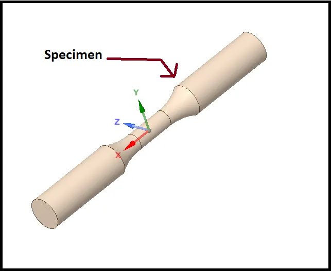
Mesh
CASE:1 {Tension Test}
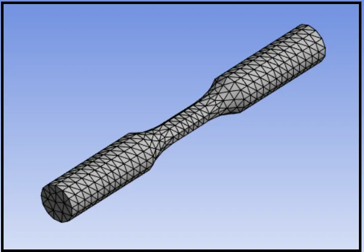
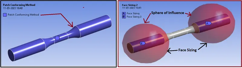
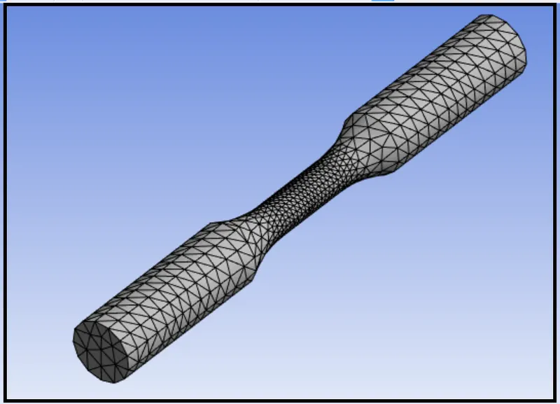
- Here we have used Patch conforming method and used Tetrahedron meshing for the Specimen body.
- Also for the sizing of the grip section, we have used face sizing and sizing is applied with help of Sphere of Influence.
CASE:2 {Torsion Test}
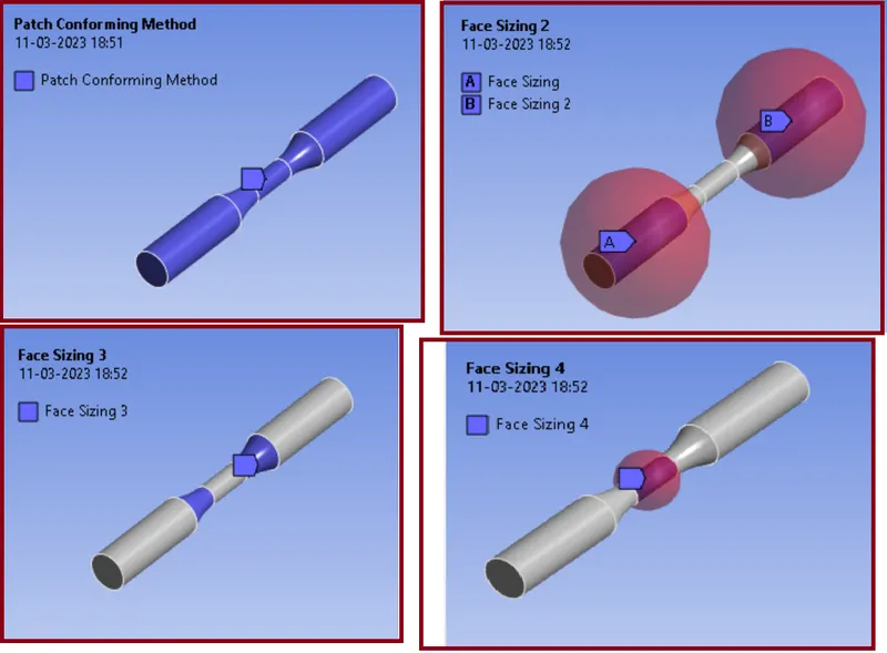
- For Torsion Test, in addition to above mesh criteria, we have used face sixing for the Shoulder areas.
- And for the Neck portion, face sizing is done with help of Sphere of Influence.
Mesh Detail:
For Tension as well as Torsion test are as given below:
- Patch conforming method: Tetrahedron
- Body: Specimen
- Face Sizing: 2 Grip Faces
- Type: Sphere of influence
- Sphere Centre: Coordinate system 1 & 2
- Sphere Radius: 22mm
- Element Size: 3 mm
- Face Sizing: Neck Portion
- Type: Sphere of influence
- Sphere Centre: Global Coordinate system
- Sphere Radius: 8 mm
- Element Size: 1 mm
- Face Sizing: 2 Shoulder Areas
- Element Size: 1.5 mm
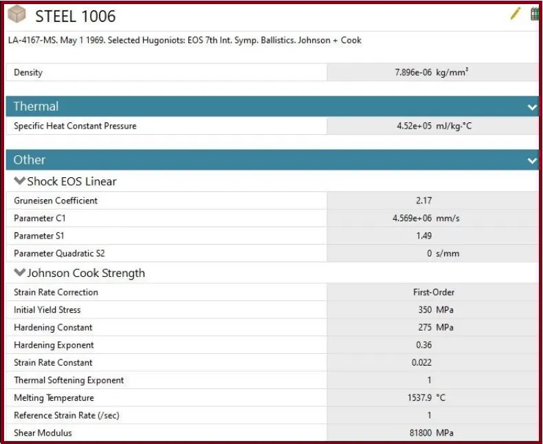
- Material {Steel 1006}
Coordinate System:
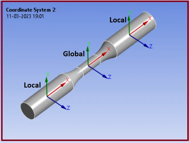
CASE:1 {Tension test}
CASE:2 {Torsion test}
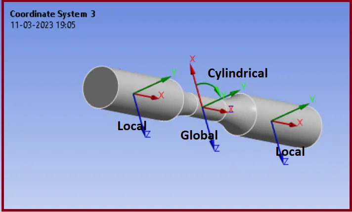
- For meshing, and use of Sphere of Influence, we have used different coordinate.
- Coordinate systems generated on the shoulder area are used for the Sphere of Influence in face sizing of different portions in Tension and Torsion Test.
- Cylindrical coordinate system is used for the angular displacement in Torsion Test.
Initial steps
- Import model in Explicit Dynamics in Geometry section.
- Then go to Mechanical model section.
- Rename the Part of the setup as Specimen.
- Boundary Conditions settings:
Our next step is creating Boundary Conditions:
Analysis Settings:
- No. of Steps: 1
- End Time: 1e-3
- Maximum Number of Cycles:1e+07
- Initial Time Step: Program Controlled
- Minimum Time Step: Program Controlled
- Maximum Time Step: Program Controlled
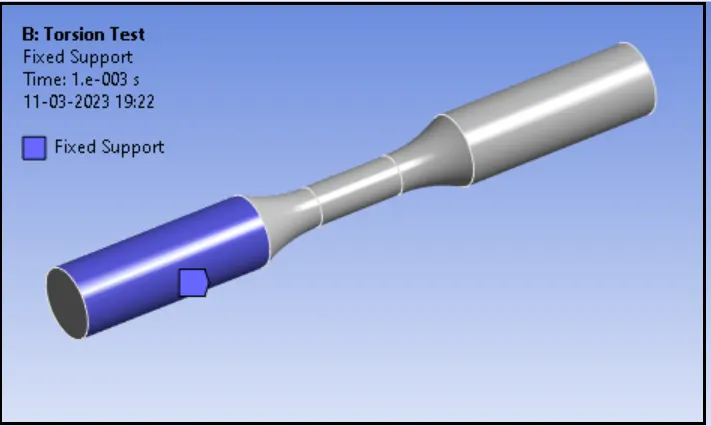
Fix Support (Tension and Torsion Test):
Keep one end of the specimen as a fixed
Displacement (For Tension Test):
Here we Apply Displacement to one end of the specimen in order to give a uniaxial Tension.
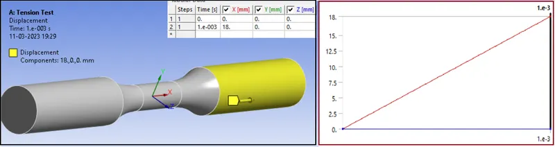
the Displacement to the one end of the specimen is given up to 18 mm in X- Direction.
Displacement (For Torsion Test):
Here we Apply Displacement (Angular) to one end of the specimen in order to generate torsion with angular displacement with help of Cylindrical coordinate.
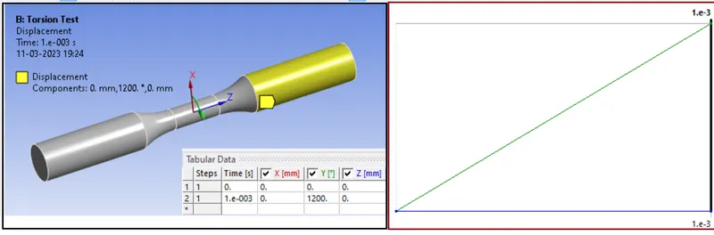
the Angular Displacement to end of the specimen is given up to 1200 degree with help of Cylindrical coordinate system, generated at the Neck portion in local rotational Y-Direction.
SOLUTION
After giving proper boundary conditions, create desired solutions for output results.
- Equivalent Stress
- User Defined Result: Temperature (With help of Worksheet)
- Total Deformation
CASE:1 {Tension test}
- Stress
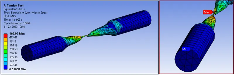
- Stress plot
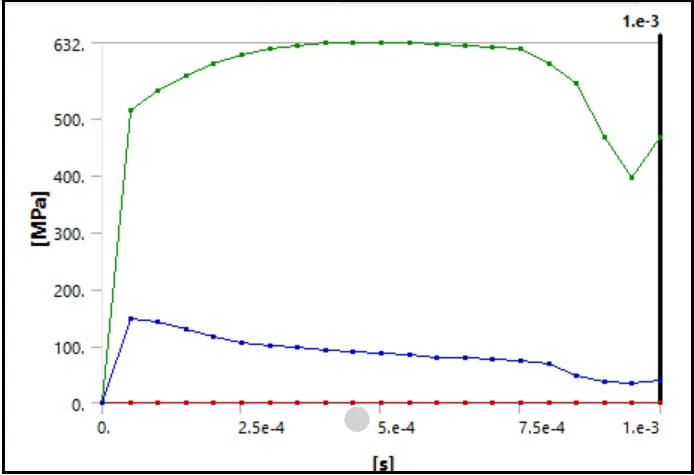
- Detailed Stress data
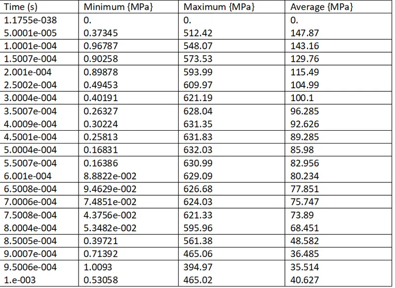
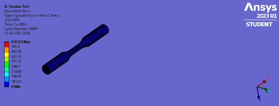
- we can observe that maximum stress on the specimen is 465.02 MPa.
- Approximately at 5e-4 s, necking happens, and then the value of stress is slightly decreasing.
- After necking, specimen will not withstand more stress, so the stress is decreasing after necking.
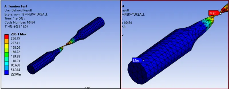
- Temperature
- Temperature plot
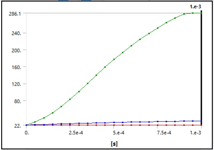
- Detailed Temperature Data
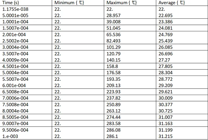
- From the results, we can observe the significant change in temperature.
- As the deformation increases, stress is also increases, and there will be heat generation.
- So, with increases in stress, we can see the rise in temperature.
- Here the temperature of the specimen is rising up to very high 286.1 Degree Celsius
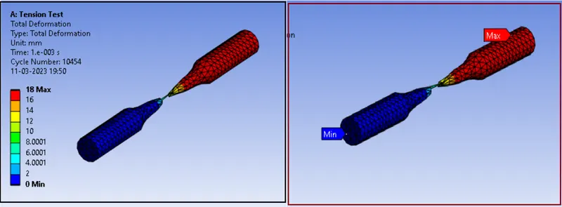
- Total Deformation
- Deformation Plot
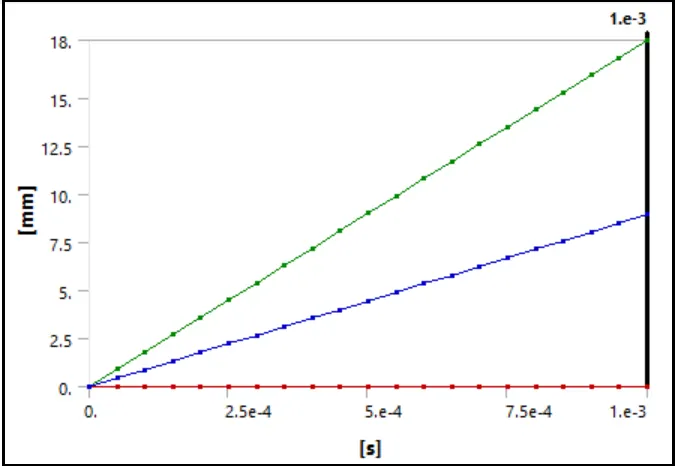
- Detailed deformation Data
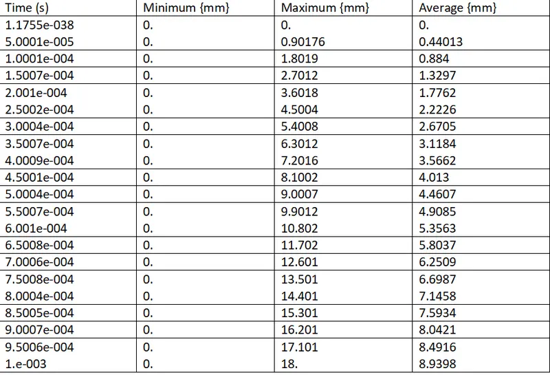
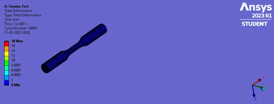
- Here we can see the maximum deformation is 18 mm.
- As we know that we have stretched the specimen up to 18 mm, so we are getting maximum value of 18 mm.
- Also, the displacement is given in X-direction, so we are getting linear graph of deformation.
CASE:2 {Torsion test}
- Stress
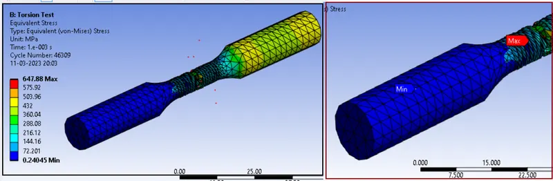
- Stress plot
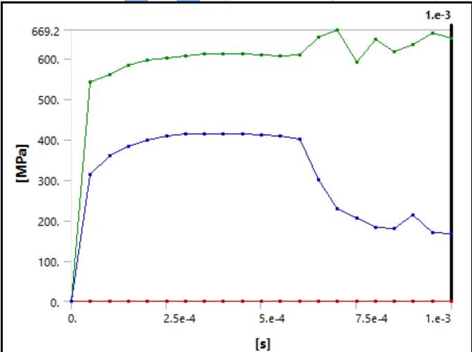
- Detailed Stress data
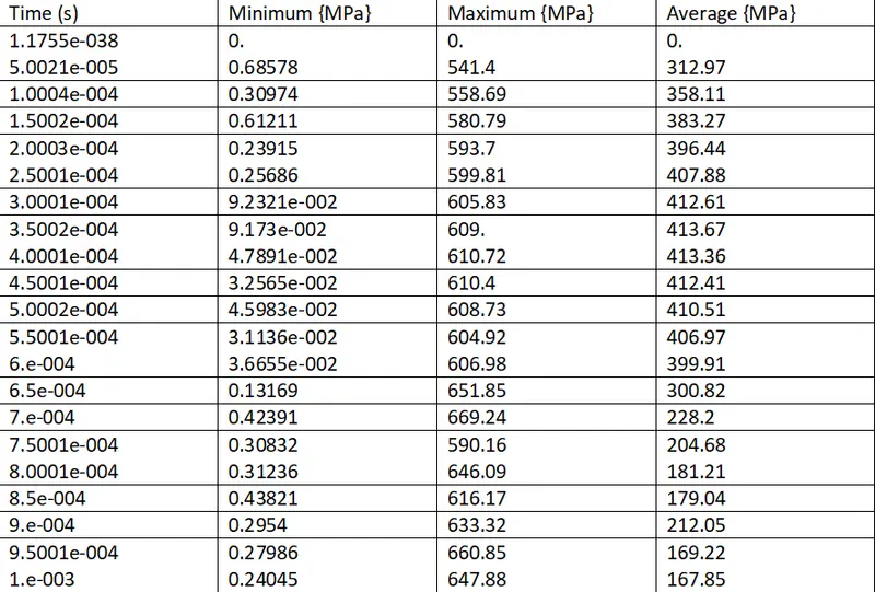
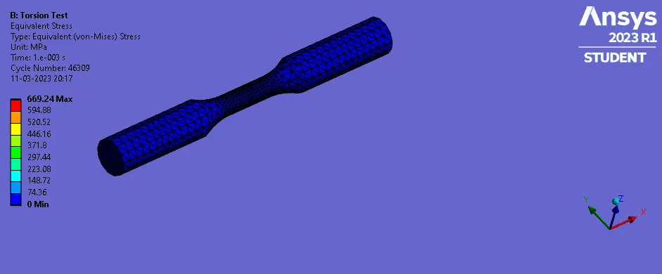
- Here we can observe that maximum stress on the specimen is 647.88 Mpa.
- We can see that there is fracture near 7.5e-4 s {Approximately from ANNIMATION}
- We can observe that to reach up to maximum stress, specimen is taking more time in torsion than tension.
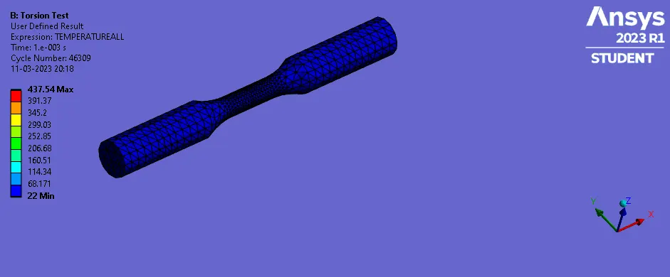
- Temperature
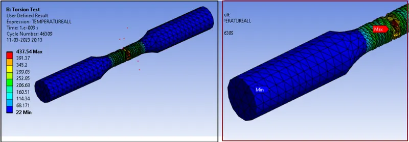
- Temperature plot
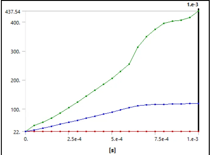
- Detailed Temperature Data
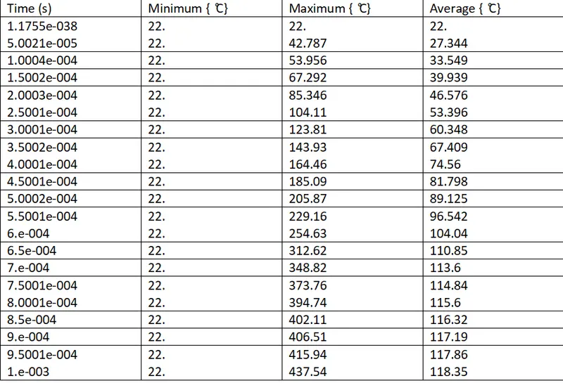
- with increases in stress, we are able to Observe the rise in temperature.
- Here from the temperature results, we can observe the high change in temperature.
- As the deformation increases, stress is also increases, and there will be heat generation.
- The temperature of the specimen is rising up to very high 437.54 degree Celsius.
- Excessive amount of heat is generating due to shearing effect at the neck area of the specimen, where twisting is happening and the particles are getting exploded due to fracture.
- Total deformation
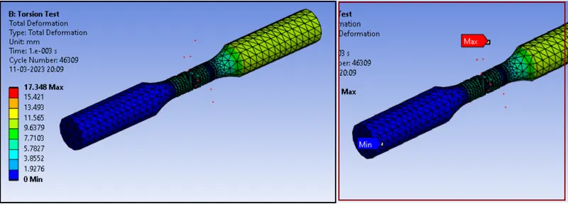
- Deformation Plot
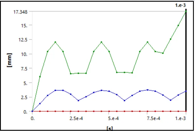
- Detailed deformation Data
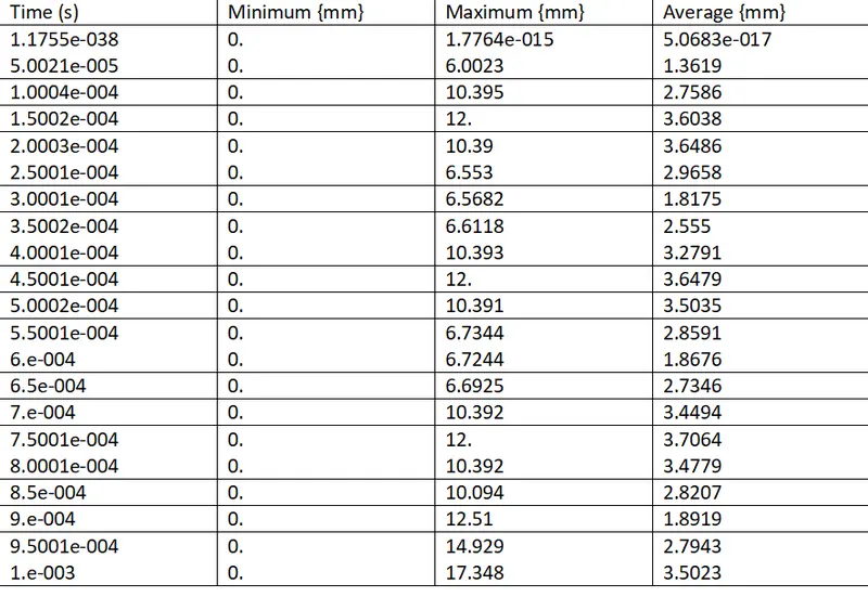
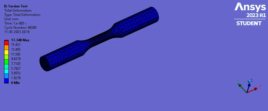
- Here We can observe the ups and downs in graph, which is due to rotation of the one end of specimen.
- the maximum deformation is 17.348 mm
- for the higher angle of rotation, very small deformation is happening.
- Also, we can see that particles are exploding due to fracture.
Result Summary:
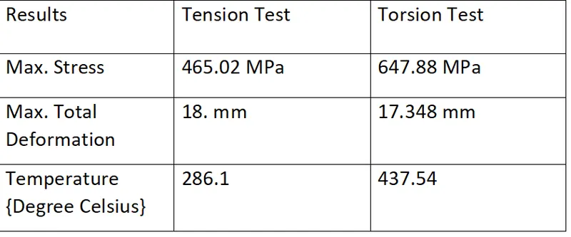
CONCLUSION:
- Here we can conclude that the failure of the specimen in Tension Test is due to permanent deformation due to elongation and sue to neck generation. This concludes that failure of the Specimen is due to max. Tensile Stress.
- Failure of the Specimen in the Torsion Test shows, the flat failure surface. This concludes that failure is due to Max. Shear Stress. Also, it is ductile material, which indicates the failure in the Plane of maximum sheer stress perpendicular to the axis of the Specimen.
- The Temperature in Torsion Test is very high due to high sheer stress.
- In Tension Test, Lateral Stress also occurs due to axial tension and reduction of the cross-section area at neck portion.
- In Torsion Test, Shear Stress is important due to twisting of the specimen in the angular direction.
- we know from the results that, the fracture in Tension Test initiates in the necked portion.
- For the Torsion Test fracture is occurring in flat surface, or in Shear plane, so steel is failing at large shear strains.
- Here the temperature is also important factor in both the Tests, as we know that at higher temperature elongation or fracture of the material can differ.
- Torsion tests are commonly used in engineering and materials science to evaluate the suitability of materials for specific applications that involve torsional loading, such as shafts, springs, and gears. They can also be used to compare the properties of different materials and to assess the effects of manufacturing processes on material properties.
ANNIMATION
CASE:1 {Tension test}
Stress
Total deformation
Temperature

CASE:2 {Torsion test}
Stress
Total deformation
Temperature
**********************************************************************************************************************************************************************************************************************************************************************END
Thanks & regards,
Devesh kashyap