Week 4 -Wire Bending Challenge
AIM: To Perform Static-Structural Analysis/Simulation for Wire Bending Operation.
OBJECTIVE:
To Perform static structural analysis/ Simulation for Wire Bending Operation.
- CASE:1 {Material for Wire - Copper Alloy NL}
- CASE:2 {Material for Wire - Aluminium Alloy}
- CASE:3 {Material for Wire - Magnesium Alloy NL}
THEORY:
Mechanical wire bending is a manufacturing process that involves bending metal wire to create various shapes and forms. This process is commonly used in the production of wire forms, such as hooks, handles, springs, and other components used in various industries.The mechanical wire bending operation involves the use of specialized machinery, such as wire bending machines, to shape the wire into the desired form. The wire is fed into the machine and then bent using a series of dies and tools that are designed to create specific shapes.
The wire bending process can be automated or manual, depending on the complexity of the shape being created. In automated systems, the wire bending machine is programmed with the specifications of the desired form, and the machine carries out the bending process automatically. In manual systems, an operator manually bends the wire using specialized tools.
Mechanical wire bending can be performed on various types of wire, including steel, stainless steel, aluminum, and brass. The wire can be bent into a wide range of shapes, including simple curves, angles, and complex forms. The wire can also be bent to tight tolerances, allowing for precision components to be created.
Overall, mechanical wire bending is a versatile manufacturing process that offers many advantages, including high precision, repeatability, and flexibility in creating a wide range of shapes and forms.
ANALYSIS SETUP:
Here we categorized Structural analysis of wire bending process will be in 3 different cases with changes of Material.
- CASE:1 {Material for Wire - Copper Alloy NL}
- CASE:2 {Material for Wire - Aluminium Alloy}
- CASE:3 {Material for Wire - Magnesium Alloy NL}
We will use different Material (CASE:1- CASE:3) and find out the Equivalent stress and Equivalent Elastic strain for wire.
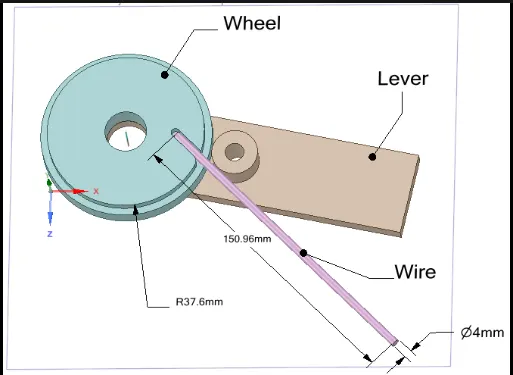
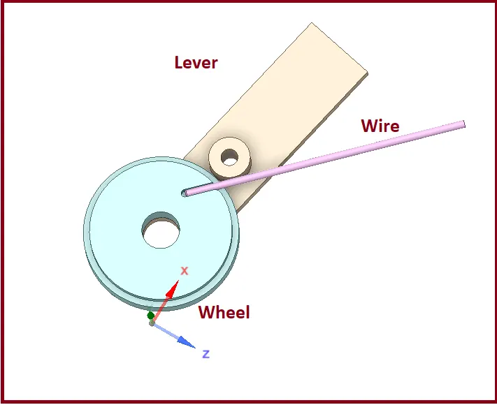
- Given Geometry:
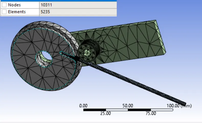
Mesh:
Details:
- Global Element Size - Default
- Quality: >> Smoothing - Low
- Patch Conforming Method - Tetrahedrons
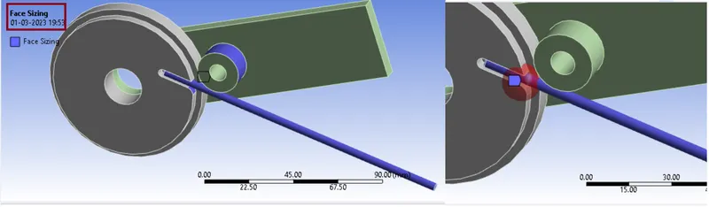
- Face Sizing - All Faces in Contact (4 Faces)
- Element Size = 1.8 mm
- Face Sizing: Wire Face (1 face)
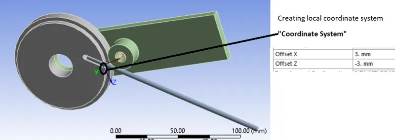
- Type: Sphere of Influence
- Sphere Centre – Coordinate system
- Sphere Radius: 7 mm
- Element Size: 0.8 mm
Material Specifications for
- CASE: 1 {Copper Alloy NL}
- Density: 8300 Kg/m3
- Young’s Modulus: 1.1 E+05 MPa
- Poisson’s Ratio: 0.34
- Yield Strength: 280 MPa
- Tangent Modulus: 1150 MPa
- CASE :2 {Aluminium Alloy NL}
- Density: 2770 Kg/m3
- Young’s Modulus: 71000 MPa
- Poisson’s Ratio: 0.33
- Yield Strength: 280 MPa
- Tangent Modulus: 500 MPa
- CASE: 3 {Magnesium Alloy NL}
- Density: 1800 Kg/m3
- Young’s Modulus: 45000 MPa
- Poisson’s Ratio: 0.35
- Yield Strength: 193 MPa
- Tangent Modulus: 920 MPa
Initial Steps
- Import model in Static Structural named as “Skill_Lync_Wire bending model.x_t” in Geometry section.
- Then go to Mechanical model section.
- Check or Rename the Parts of the setup as “Wheel”, “Wire” and “Lever” as shown in above geometry.
- Connections:
Very first we need to Delete automatically created contacts and create new contacts as given below:
Contact: 1st one
- Contact Body = Wire
- Target Body = Lever
Contact: 2nd one
- Contact Body = Wheel
- Target Body = Wire
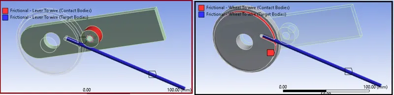
Settings we need to edit for Both the Contacts.
- Type: Frictional
- Friction Coefficient: 0.2
- Formulation: Augmented Lagrange
- Normal Stiffness: By factor
- Normal Stiffness Factor: 0.1
- Update Stiffness: Each Iteration
- Interface Treatment: Add Offset, Ramped Effects
Joints:
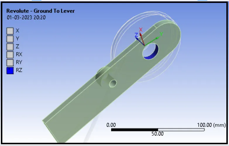
- Joint: 1st
Connection Type: Body-Ground
Type: Revolute
Body: Lever
Boundary Conditions settings:
Our next step is creating Boundary Conditions:
Analysis Settings:
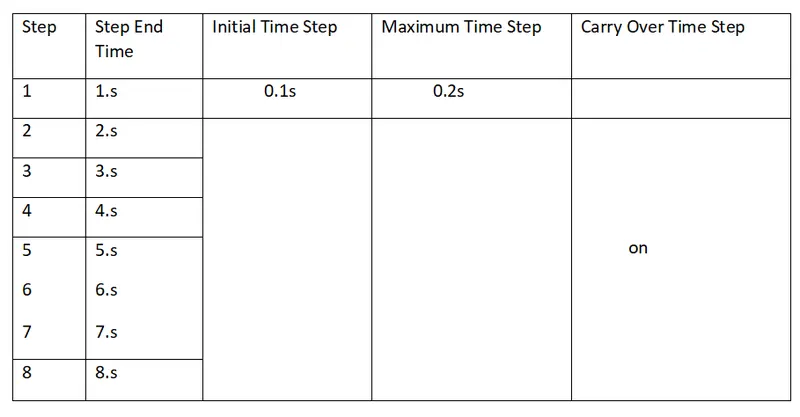
Total No. of Steps: 8
For 1st Step:
- Solver Type: Direct
- Large Deflection: ON
- Auto Time Stepping: ON
- Defined By: Time
- Initial Time Step: 1 s
- Minimum Time Step: 0.01 s
- Maximum Time Step: 0.2 s
- Output Controls: All Yes
For 2nd to 8th Steps
- Solver Type: Direct
- Large Deflection: ON
- Auto Time Stepping: ON
- Defined By: Time
- Carry Over Time Step: ON
- Minimum Time Step: 0.01 s
- Maximum Time Step: 1 s
- Output Controls: All Yes
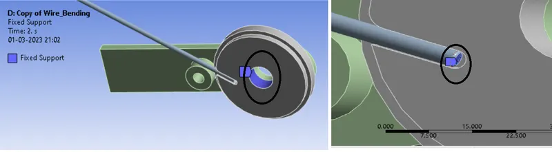
- Fixed Support:
Here we Apply Fixed Support for fixing the movement of Wheel and Wire
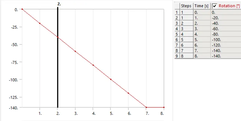
Joint Load:
Joint: Revolute - Ground To Lever
Type: Rotation
Magnitude: Tabular Data
SOLUTION
After giving proper boundary conditions, create desired solutions for output results. Create Solutions for Equivalent (Von Mises) Stress for wire, Equivalent (Von Mises) Strain for the wire.
Comparison of CASE:1 {Material for Wire - Copper Alloy NL}, CASE:2{Material for Wire - Aluminium Alloy} and CASE :3{Material for Wire - Magnesium Alloy NL}
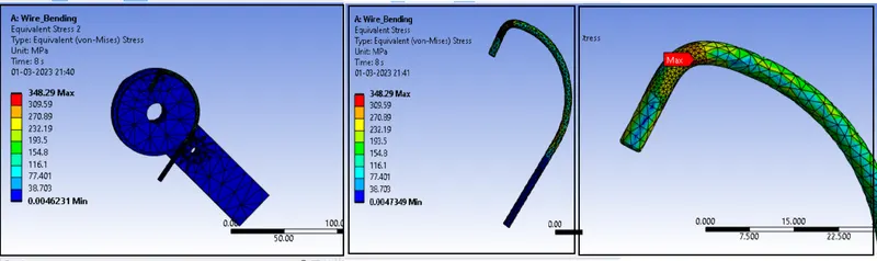
- Stress in CASE:1 {Material for Wire - Copper Alloy NL}
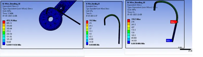
Stress in CASE:2 {Material for Wire - Aluminium Alloy}
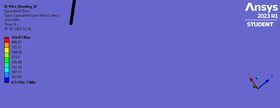
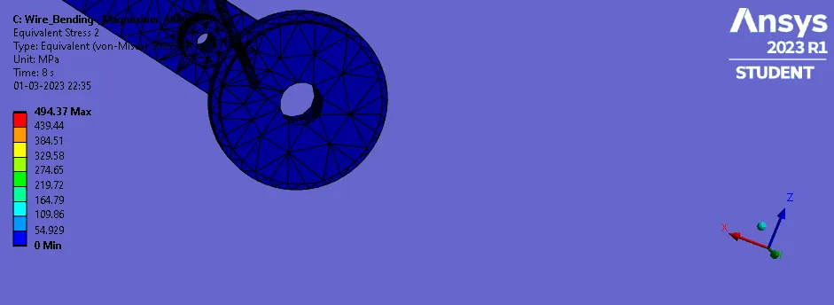
Stress in CASE :3{Material for Wire - Magnesium Alloy NL}
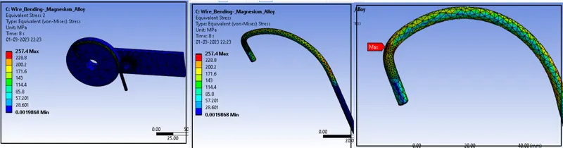
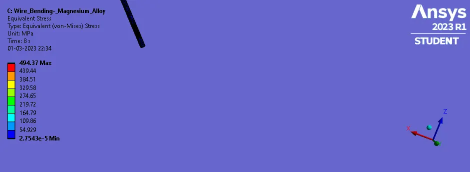
Stress plot CASE:1 {Material for Wire - Copper Alloy NL}
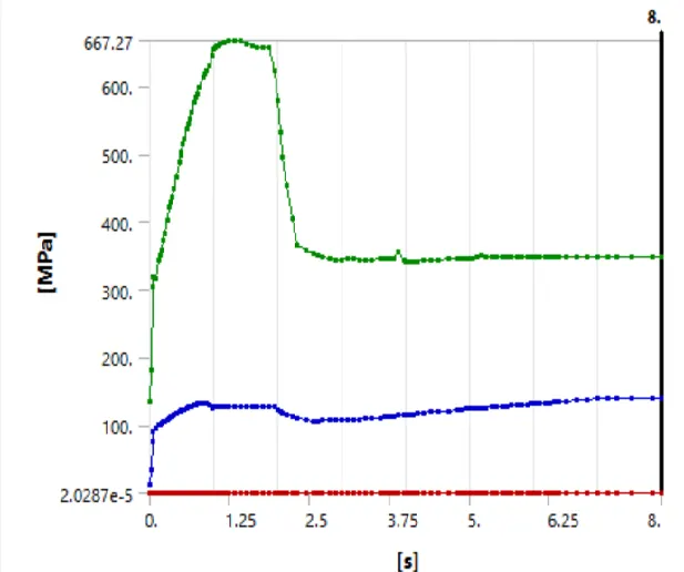
Stress plot CASE:2 {Material for Wire - Aluminium Alloy}
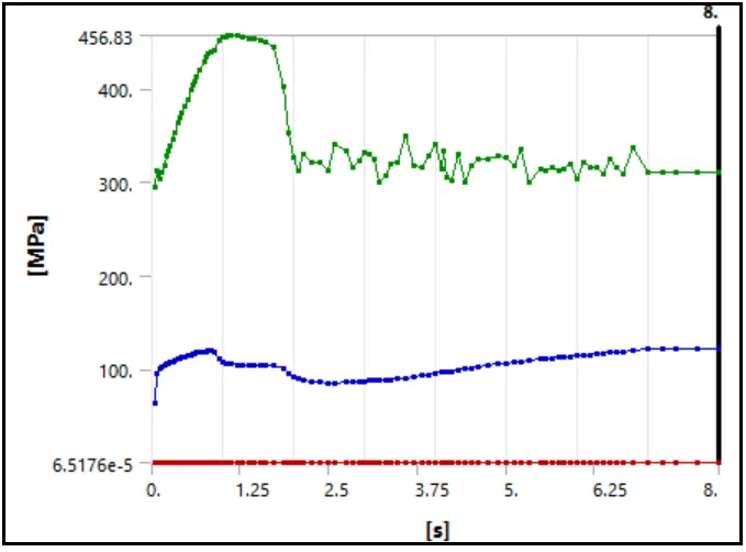
Stress plot CASE :3{Material for Wire - Magnesium Alloy NL}
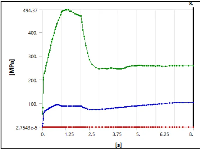
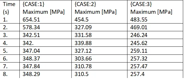
Stress Data for {Copper Alloy NL (CASE:1) , Aluminium Alloy NL (CASE:2) , and Magnesium Alloy NL (CASE:3) }:
-----------------------------------------------------------------------------------------------------------------------------------------------------------------------------------------
ANIMATION..
CASE:1
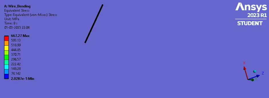
CASE:2
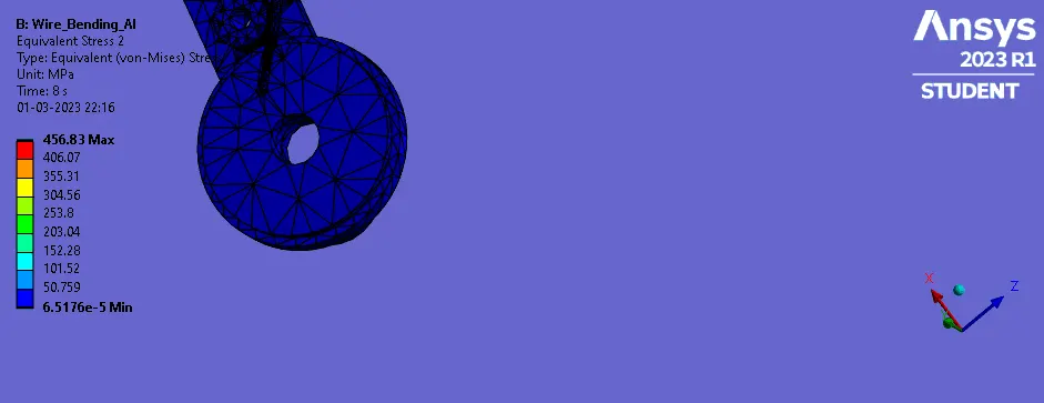
CASE:3
--------------------------------------------------------------------------------------------------------------------------------------------------------------------------------------------------
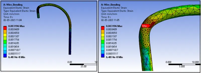
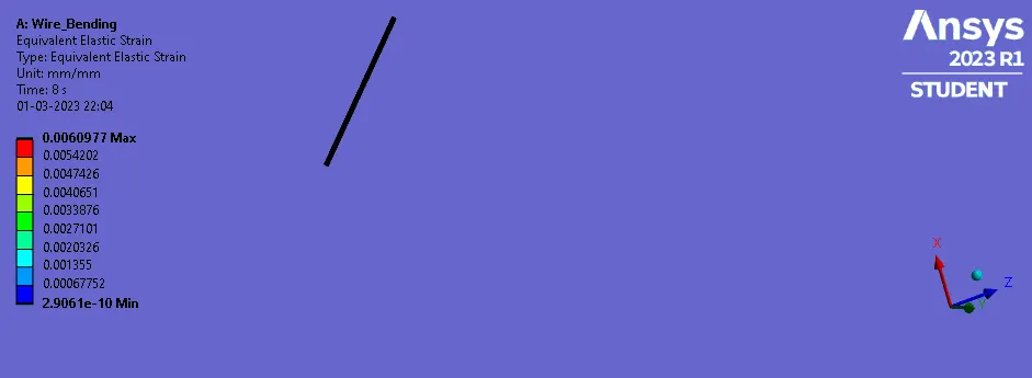
- Strain in CASE:1 {Material for Wire - Copper Alloy NL}
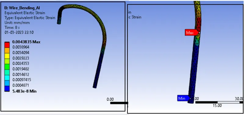
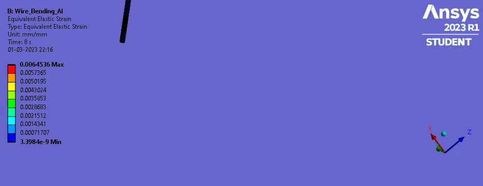
- Strain in CASE:2 {Material for Wire - Aluminium Alloy}
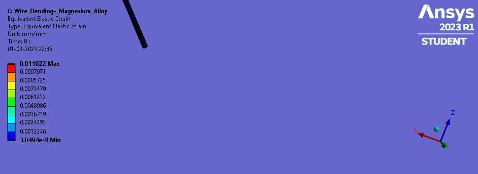
- Strain in CASE :3{Material for Wire - Magnesium Alloy NL}
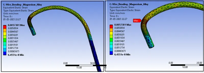
Strain plot CASE:1 {Material for Wire - Copper Alloy NL}
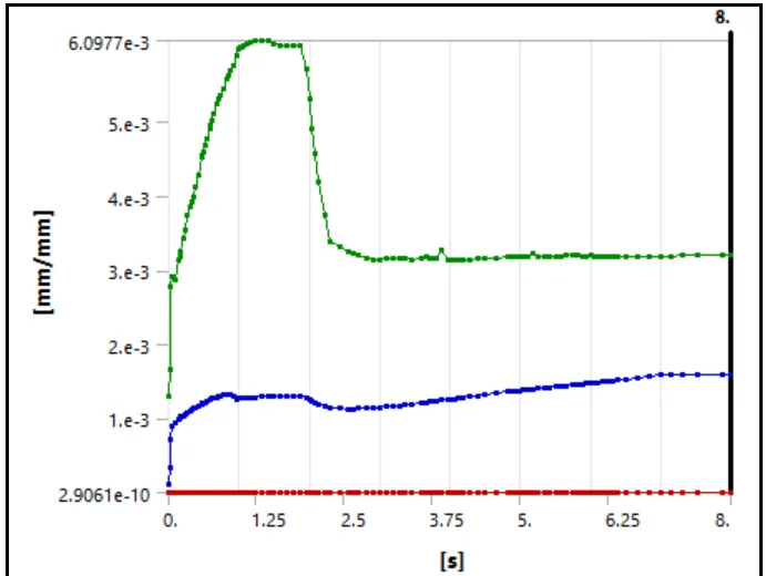
Strain plot CASE:2 {Material for Wire - Aluminium Alloy}
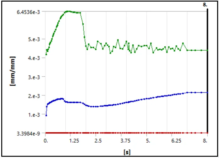
Strain plot CASE :3{Material for Wire - Magnesium Alloy NL}
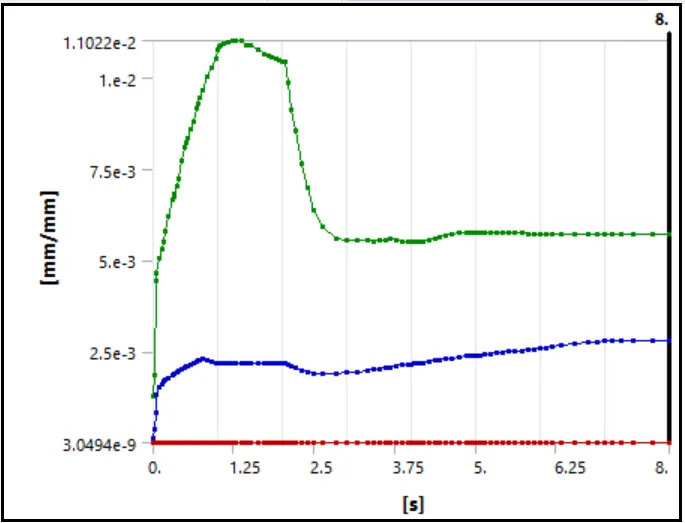
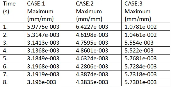
Strain Data for {Copper Alloy NL (CASE:1) , Aluminium Alloy NL (CASE:2) , and Magnesium Alloy NL (CASE:3) }:
-----------------------------------------------------------------------------------------------------------------------------------------------------------------------------------------
ANIMATION..
CASE:1
CASE:2
CASE:3
---------------------------------------------------------------------------------------------------------------------------------------------------------------------------------------------------
COMPARISONS
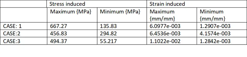
- Here we can observe that Copper Alloy NL faces high stress compare to other two material {Aluminium Alloy NL (CASE:2), Magnesium Alloy NL (CASE:3)}. So, we can say that it is stiffer than other two materials and can be hard for bending.
- We can observe that Magnesium Alloy NL material has higher strains. Because of low Yield Strength, it is will deform early and easy for bending.
- We can observe that in case of Copper Alloy and Magnesium Alloy, stress and strain develops maximum at the contact region but in case of Aluminium Alloy, it is in lower part of wire. So Aluminium Alloy does not behave properly and can lead to spring back effect.
CONCLUSION:
- The stiffness of a wire refers to its resistance to bending or deformation under an applied load. In wire bending, stiffness is an important factor because it affects the ease with which the wire can be bent into the desired shape and the accuracy of the resulting bend. The stiffness of a wire depends on several factors, including its material properties, diameter, and length. For example, wires made of materials with high modulus of elasticity, such as steel or titanium, are stiffer and more difficult to bend than wires made of softer materials such as copper or aluminium.
- Also, Formability is important factor which shows the area between breaking point and plastic deformation for material.
- In terms of bending process, we can see from the results that Magnesium Alloy NL can be bent very easily. It does not need high load for bending.
- Application of wire determines which the material should be used for bending. In electric components, we can see that Copper material is used due to their supper elasticity. But in case where conductivity is not important, we can use Magnesium Alloys for their easy bending process.
******************************************************************************************************************************************************************************************************************************************************************************END
Here Due to large size of the Ansys file, I have attached a link for the Ansys .wbpz file in below "Model Browse" area.
Kindly find attached link via word document.
Thanks & regards,
Devesh kashyap