Week 9 Machining with Planer Challenge
AIM: To perform the Explicit Dynamics Analysis for Planer machining operation by using ANSYS Work bench.
OBJECTIVE:
To perform an explicit dynamics simulation to find out the Equivalent Stress, Total Deformation and User defined result to calculate the temperature of the body. We need to perform this for 2 cases.
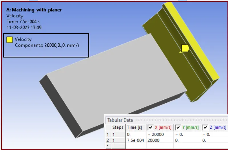
- CASE:1 The cutting velocity of 20000mm/s.
- CASE:2 The cutting velocity of 15000mm/s.
THEORY:
- Explicit dynamics analysis is a type of numerical simulation that uses finite element analysis (FEA) to predict the behavior of a system under dynamic loading conditions. In the context of planar machining, explicit dynamics analysis can be used to model the behavior of the workpiece and cutting tool during the machining process.
- In planar machining, the workpiece is typically a flat plate or sheet of material that is held stationary while a cutting tool moves across its surface to remove material and shape it into the desired form. During this process, forces are applied to the workpiece and cutting tool, which can cause deformation, vibration, and other dynamic effects.
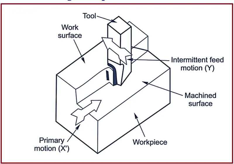
- To model these effects using explicit dynamics analysis, the workpiece and cutting tool are divided into discrete finite elements, and the forces acting on each element are calculated based on the cutting forces, friction, and other factors. The equations of motion for each element are then solved iteratively over a short time step to predict their behavior over time.
- By simulating the machining process using explicit dynamics analysis, engineers and manufacturers can optimize their cutting parameters, tooling, and workpiece material to achieve the desired machining results while minimizing waste and reducing the risk of damage to equipment and personnel.
Explicit dynamics analysis has several properties that make it well-suited for modelling dynamic events and systems:
- Time-dependent behaviour: Explicit dynamics analysis is particularly useful for modelling systems that exhibit time-dependent behaviour, such as impacts, explosions, and material failure. This is because explicit dynamics analysis solves the equations of motion for each element of the system over a short time step, allowing for accurate modelling of rapid changes in behaviour.
- Large deformations: Explicit dynamics analysis can handle large deformations of the system, such as those that occur during impact or material failure. This is because the finite element method used in explicit dynamics analysis allows for large displacements and rotations of the elements.
- Nonlinear behaviour: Explicit dynamics analysis is able to model nonlinear behaviour, such as plastic deformation, material failure, and friction. This is because the equations of motion for each element are solved iteratively over short time steps, allowing for accurate modelling of nonlinear effects.
- Accurate contact modelling: Explicit dynamics analysis can accurately model contact between elements, such as between the cutting tool and workpiece during planar machining. This is important for accurately predicting the behaviour of the system, as contact can have a significant impact on the forces and deformation experienced by the elements.
- Computational efficiency: Explicit dynamics analysis is computationally efficient for modelling short-duration events, as the equations of motion for each element are solved iteratively over short time steps. This makes it well-suited for modelling systems that undergo rapid changes in behaviour, such as those that occur during impact or material failure.
ANALYSIS SETUP:
Here we will start our work analysis of a machining with a Planer in two different cases.
These Two different cases based on the cutting tool velocity.
CASE:1 {Cutting velocity 20,000 mm/s}
CASE:2 {Cutting velocity 15,000 mm/s}
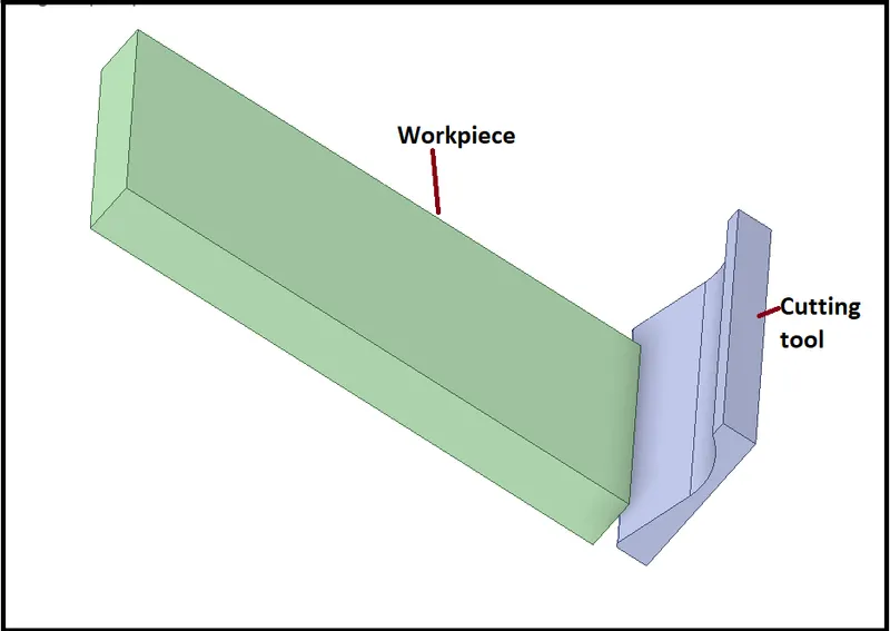
- Given Geometry
- Mesh:
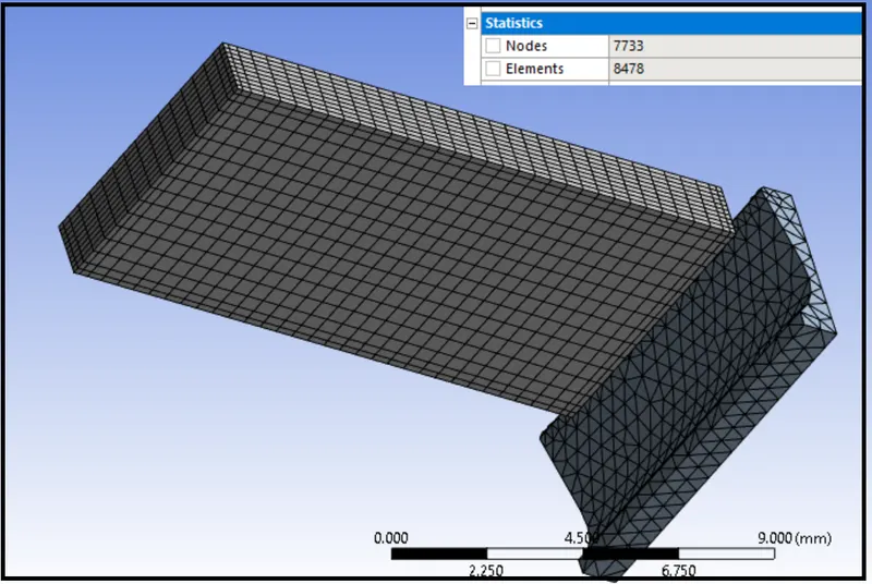
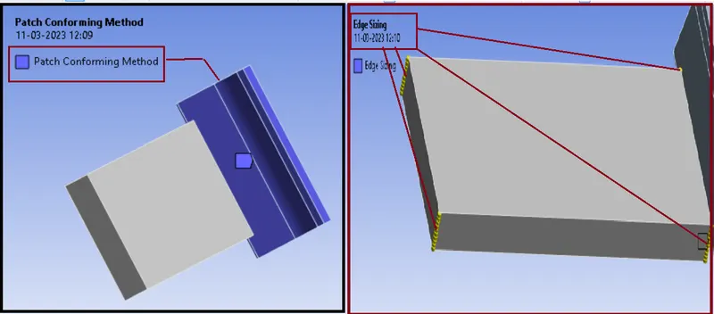
Mesh Details:
- Patch conforming method: Tetrahedron
- Body: Cutting Tool
- Edge Sizing: 4 short Edges
- Type: No. of Divisions
- No. of Divisions: 10
Material {STEEL 1006}
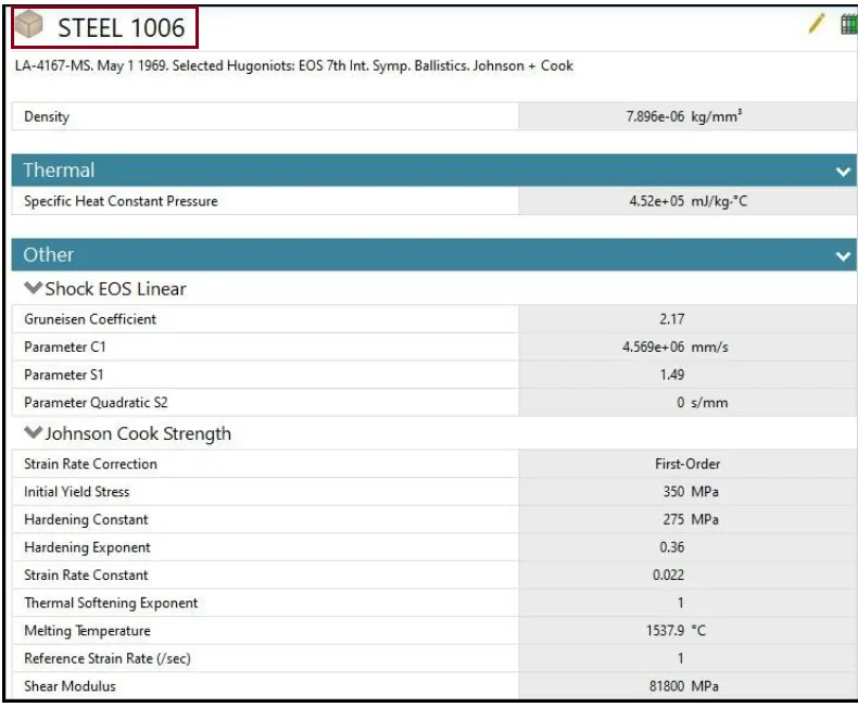
Initial steps
- Import model in Explicit Dynamics in Geometry section.
- Then go to Mechanical model section.
- Rename the Parts of the setup as Workpiece and Cutting Tool.
Boundary Conditions settings:
Our next step is creating Boundary Conditions:
Analysis Settings:
- No. of Steps: 1
- End Time: 7.5e-4
- Maximum Number of Cycles:1e+07
- Maximum Energy Error: 0.1
- Initial Time Step: Program Controlled
- Minimum Time Step: Program Controlled
- Maximum Time Step: Program Controlled
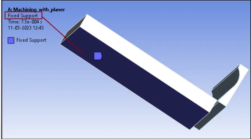
Fix Support (For Both the CASES):
Here we need to Keep bottom face of the Workpiece as a fixed to hold it while the machining is happened.
Velocity (CASE: 1)
Here we Apply velocity to Cutting Tool in the positive X-Direction
Velocity (CASE:2)
Here we Apply velocity to Cutting Tool in the positive X-Direction
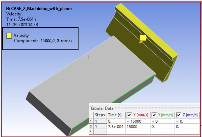
the velocity of the Cutting Tool is 15000 mm/s.
SOLUTION
After giving proper boundary conditions, create desired solutions for output results.
- Equivalent Stress
- Total deformation
- User Defined Result: Temperature (With help of Worksheet)
CASE:1 {Cutting velocity 20,000 mm/s}
- Equivalent Stress
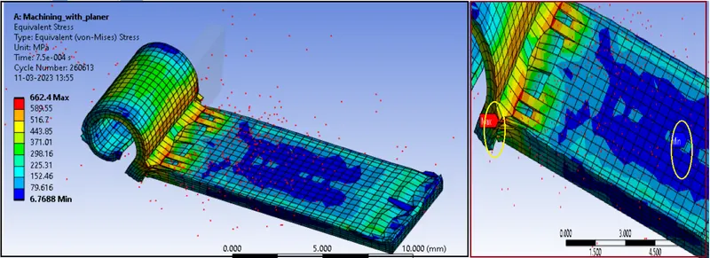
- Stress plot
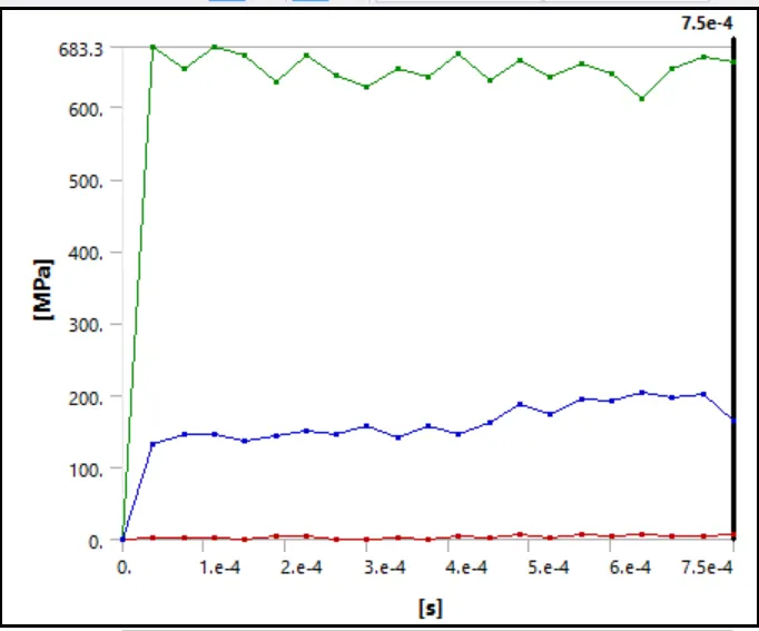
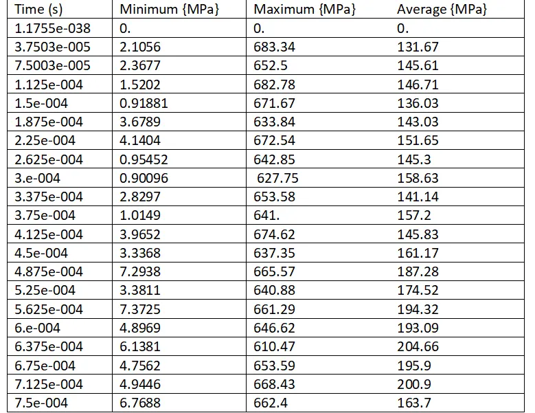
- Detailed Stress data
Comment:
- The max. stress is induced at the edge of cutting tool, from where the chip is generated due to cutting.
- Here we can observe Maximum stress is 662.4 MPa at the end.
- AS per the plots and data, we can see that, once the value of stress reached up to 683.3 MPa, then it Fluctuate nearby it during the cutting time
- Total deformation
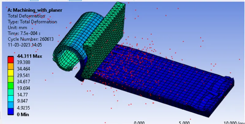
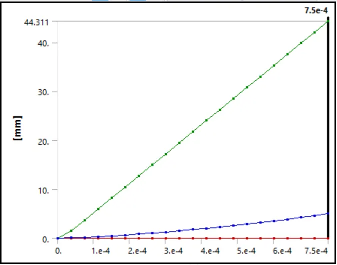
- Deformation Plot
- Detailed deformation Data
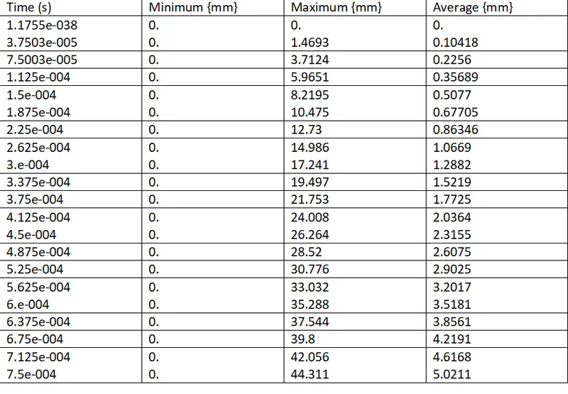
The maximum value of Total deformation is 44.311 mm.
- Temperature
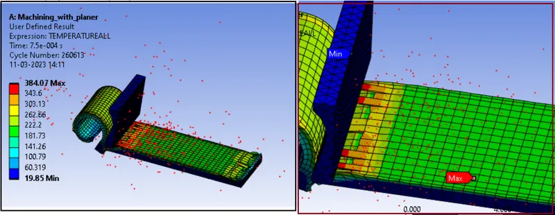
- Temperature plot
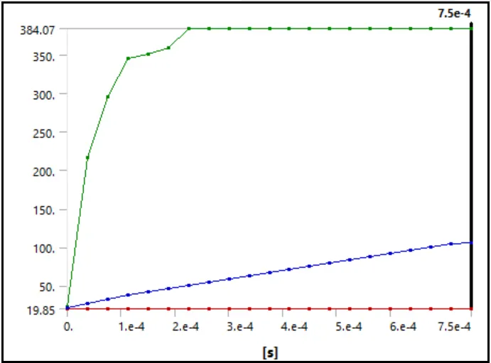
- Detailed Temperature Data
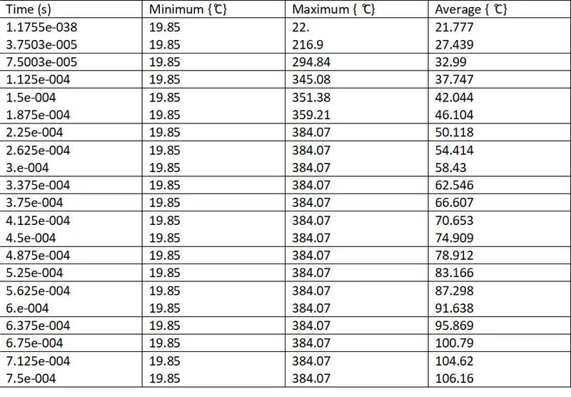
Here we can observe due to high cutting velocity the temperature is going up to max. 384.07 ̊C.
CASE:2 {Cutting velocity 15,000 mm/s}
- Equivalent Stress
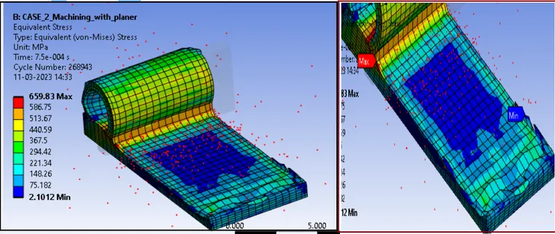
- Stress plot
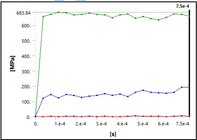
- Detailed Stress data
- We can see the red portion where max. Stress is occurring at the edge of cutting tool. Chip is generating due to cutting and to resist the tool, very high stress is observed.
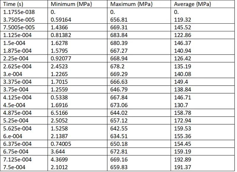
- Here we observe Maximum stress is 659.83 MPa at the end.
- From the plots and data, we can see that, once the value of stress reached up to 683.84 MPa, then it ranges nearby it during the cutting time.
- Total deformation
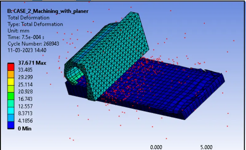
- Deformation Plot
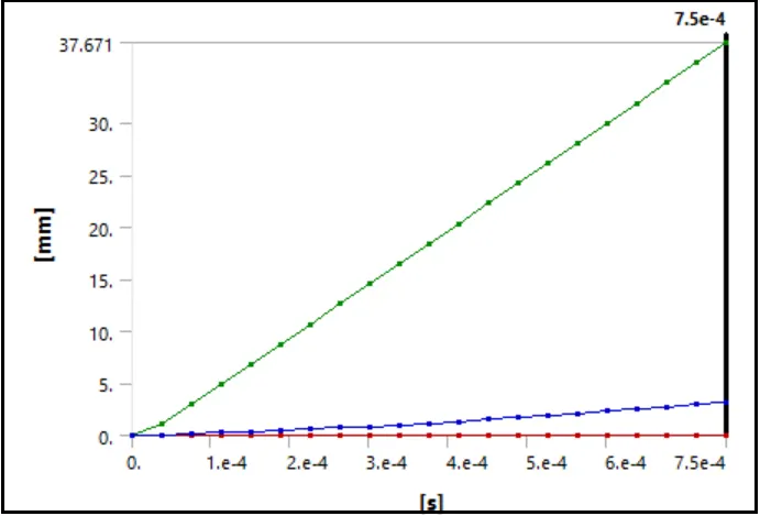
- Detailed deformation Data
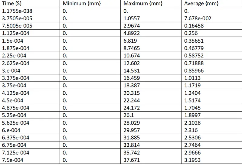
The maximum value of Total deformation is 37.671 mm.
- Temperature
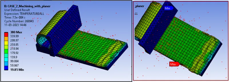
- Temperature plot
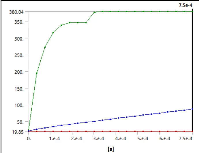
- Detailed Temperature Data
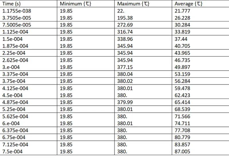
Due to high cutting Velocity, we can see the temperature is going up to max. 380.04 ̊C
Result Summary:
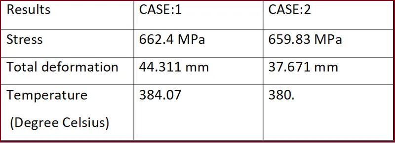
- Here we observe that the stress in CASE: 1 is higher (when the velocity is 20000 mm/s.) then CASE:1 (when velocity is 15000 mm/s).
- Similarly Total deformation is also higher in CASE :1 as compare to CASE: 2.
- Temperature is also Higher in CASE:1 as compare to CASE:2.
CONCLUSION:
- We can observe excessive increase in the temperature during the machining process.
- we can conclude that during the planer machining, high stresses in the chip formation zone, secondary deformation zone as well as on the machined surfaces can be generated.
- Intensity of stress and the behaviour of the chip formation depend on the sheer angle of the cutting tool.
- When the velocity of the cutting tool is low, stress is high, which can cause the failure of the cutting tool or the wearing of the tool, will be high.
- By analysing different velocity of cutting tool, we can find the optimum velocity and can reduce the stress generation on the workpiece.
*********************************************************************************************************************************************************************************************************************************************************************END
Thanks & regards,
Devesh kashyap