Assignment 6-Frontal Crash Simulation Challenge
AIM: To perform frontal car crash Analysis and request for Time History plots.
OBJECTIVE:
The Objective is to simulate for following problem statements.
- Sectional force in the rails at location of indicated node 174247.
- Axial force received on the rails from bumper.
- Shotgun cross sectional forces.
- A pillar cross section.
- Acceleration curve received on the accelerometer at base of B pillar (on B pillar rocker).
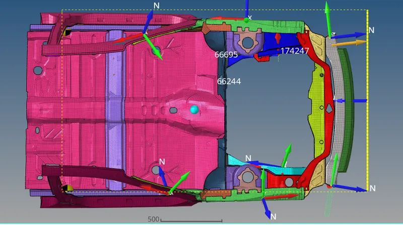
- Intrusions on the dash wall 66695,66244.
THEORY:
- A frontal car crash is a type of collision that occurs when two vehicles traveling in opposite directions collide head-on. These types of crashes can be very serious and often result in severe injuries or fatalities.
- When analysing a frontal car crash, there are several factors to consider, including the speed at which the vehicles were traveling, the size and weight of the vehicles involved, the angle of impact, and the use of safety equipment like seat belts and airbags.
- One of the most important factors in a frontal car crash is the speed at which the vehicles were traveling. The force of the impact is directly proportional to the speed of the vehicles, so higher speeds will result in more severe damage and injuries. The weight and size of the vehicles can also affect the outcome of the crash. Heavier vehicles, such as trucks and SUVs, have more mass and are more likely to cause serious damage in a collision.
- The angle of impact is another crucial factor to consider when analysing a frontal car crash. If the collision occurs at a slight angle, the vehicles may spin or slide away from each other, reducing the force of the impact. However, if the vehicles collide head-on, the force of the impact will be much greater and can cause significant damage.
- Finally, the use of safety equipment can greatly affect the outcome of a frontal car crash. Seat belts and airbags can help to absorb the force of the impact and reduce the likelihood of serious injuries or fatalities. However, if these safety features are not used correctly or are defective, they may not be effective in protecting the occupants of the vehicle.
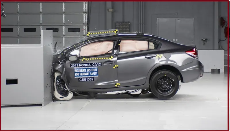
In conclusion, analysing a frontal car crash involves considering several factors, including the speed, size and weight of the vehicles involved, the angle of impact, and the use of safety equipment. By carefully examining these factors, experts can better understand the cause and severity of the crash, and develop strategies to prevent similar accidents from occurring in the future.
PROCEDURE/STEPS: -
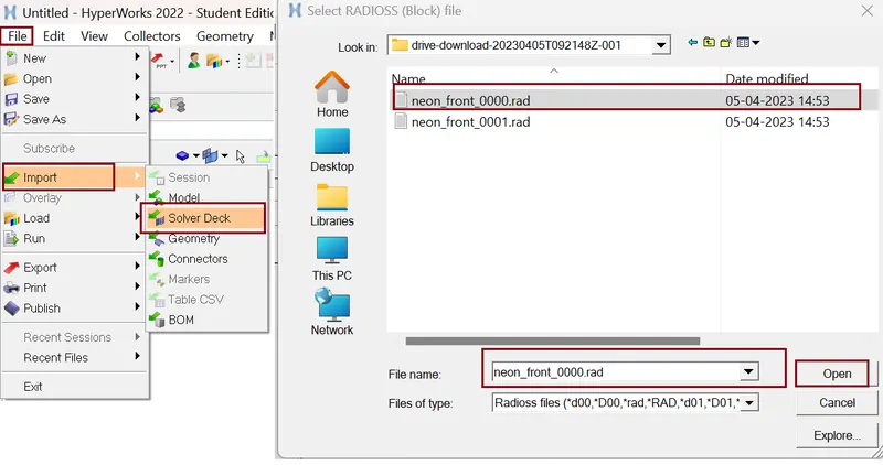
- Import the model
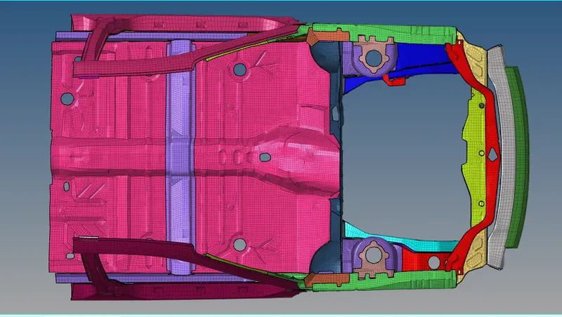
Very first we Import the ".rad" starter file of the model, "neon_front_0000.rad" in Radioss using Import Solver Deck option.
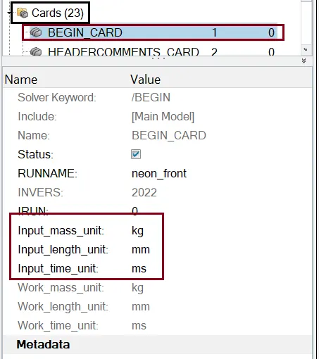
- Checking for unit system
Command: Model >> Cards >> BEGIN_CARD
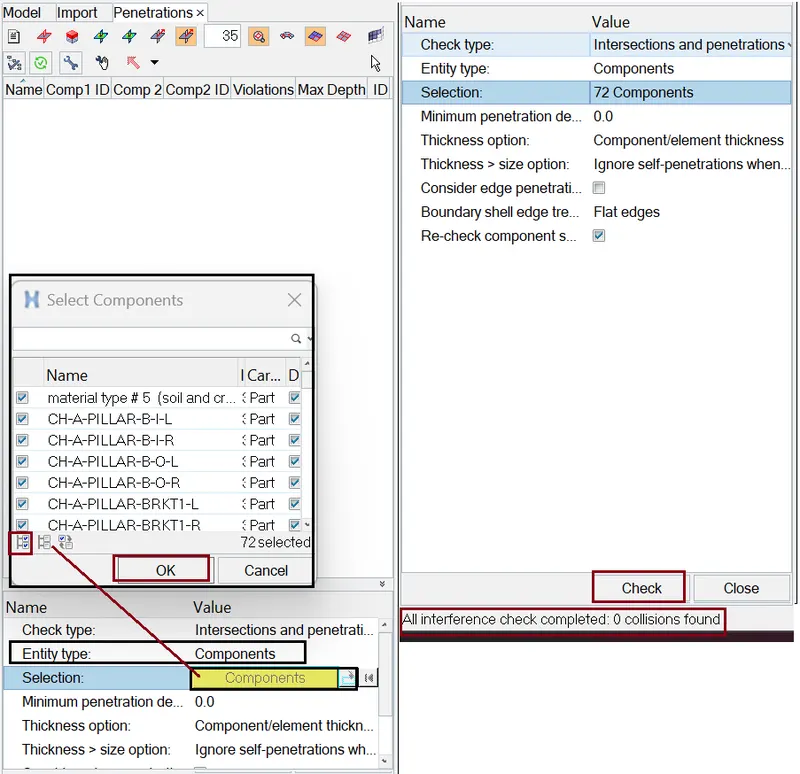
- Checking for Penetration and intersection
Command: Tools >> Penetration check >> Edit the card as per figure below.
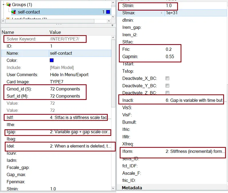
- Create appropriate interface
Here we use Type-7 Node to surface contact for Both the Slave nodes and the Master nodes.
- Correct rigid bodies if any issues
As there is no penetrations and intersections there is no need of rigid bodies.
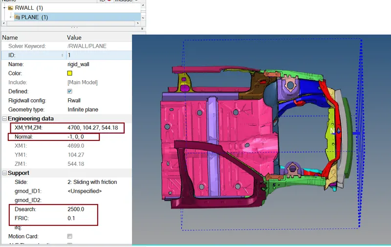
- Create rigid wall with friction 0.1
- Command: Solver Deck >> Right click >> Rwall >> plane.
- Select any node on the bumper and change the x-coordinate such that a gap is maintained.
- sliding friction with value of 0.1.
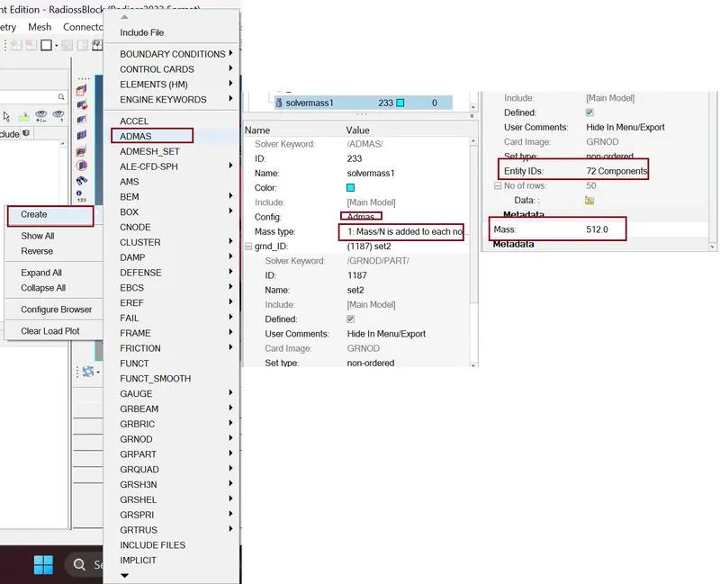
- Reach the target weight of 700 kg while getting CG about the required range
To compare the model weight with the full scale 300k nodes model and use added masses to reach target weight 700kg while getting CG about the required range. The given model was less in mass with 188 kg.
Command: Tools >> Mass Details >> Mass, cog and inertia.
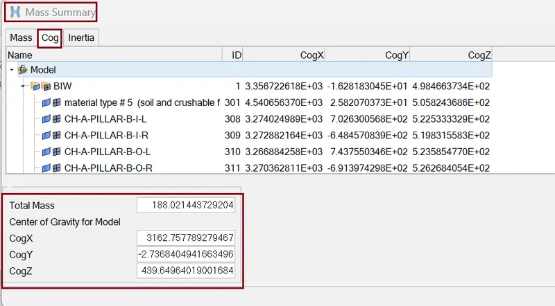
- Existing mesh 188 kg
- Required mass 700 kg
- Additional mass 582 kg
To add additional mass to achieve the required weight,
We use Command: Solver >> ADMAS
- Applying initial velocity
solver >> create >> boundary conditions >> INIVEL
- Initial velocity 35 mph.
- Converting 35mph into ms
- 1mph = 0.447 ms
- So, 35mph = 15.6464 ms
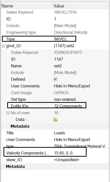
Define the Node group on which specified initial velocities are applied (grnd_ID1). For our simulation, we will be selecting the whole vehicle setup.
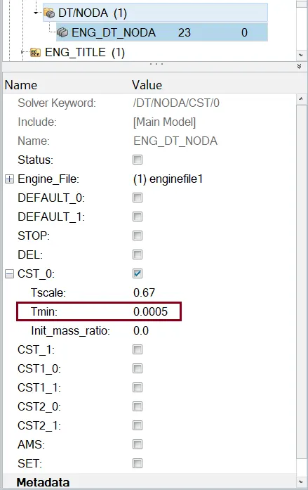
- Creating Time-step (0.5 to 0.1 microseconds)
We use command :Solver >> ENGINE_KEYWORDS >> DT/NODA
- Simulation Run time
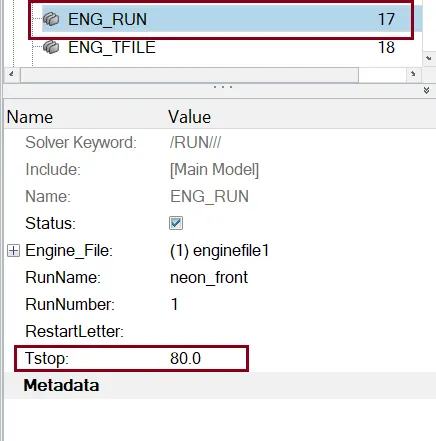
- 80 ms
Goto Model browser >> Cards >> Eng_Run >> Tstop = 80.
- CREATING SECTIONS:
Now we will be Creating Sections at A-Pillar, Shot Gun, rails, and the Bumper in order to Study the sectional forces. We have to know how the forces are transmitted from the Bumper to the Dashboard and the rate of deformation. It is done in order to ensure the safety of the passenger.
Certain components have to deform more than the other so that the forces are distributed correctly leaving very little force left to transmit inside the cabin.
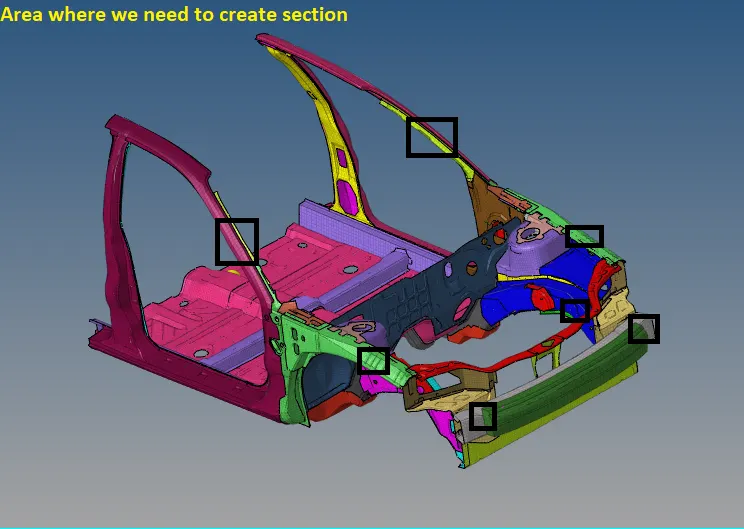
We will be using moving frames to create a section as shown below.
For creating Moving FRAME we use solver >> right click >> create >> FRAME >> MOV select the three node as given below and hit create.
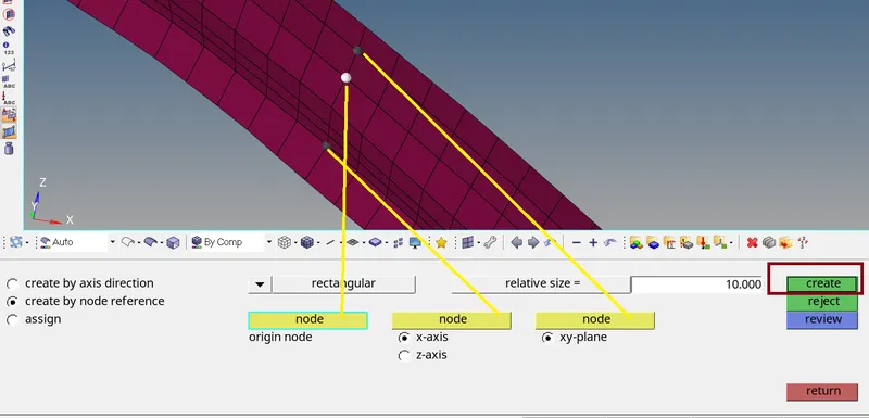
We will be using moving frames to create a section as shown below.
For creating Section, we use solver >> right click >> create >> SECT. select the N1, N2 and N3 in similar way as previous .
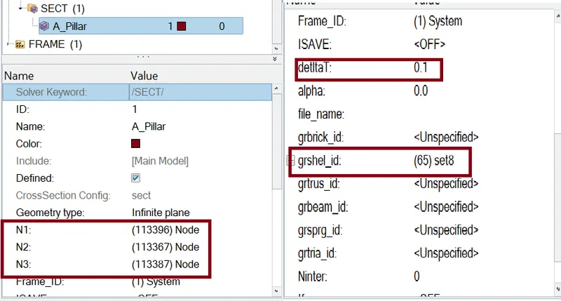
Define the Nodes with reference to the Axis of the Frame.
- Enter the values of Delta T as 0.1
- Define the cutting plane by a group of elements and its orientation by a group of nodes (grshell_ID)
- Hence, the sections will be created.
Finally we create a section
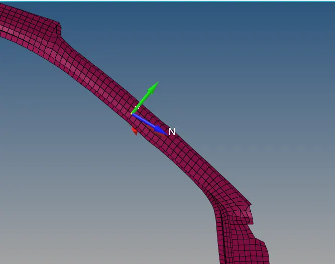
Similarly, we create all the section.
- CREATE ACCELERATION NODES:
An accelerometer is a basic technology that converts mechanical motion into an electrical signal. It is an electromechanical device that measures acceleration forces, whether caused by gravity or motion
Creating Accelerometer at both sides of the B pillar.
To create accelerometer
Go to Model browser >> Create >> Accelerometer >> Select Node_ID >> Select node >> Proceed
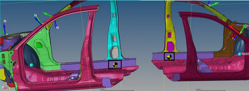
This is done to get the Acceleration output of the Crash i.e., rate of deformation.
- Intrusions on the dash wall 66695,66244.
Steps
- Find the node 66695 and 66244
Shift+F5 >> find entity >> click on node and select “by id” >> enter node number >> hit find.

- Create a moving skew
solver >> right click >> create >> skew >> MOV select the three node.

- Measure the distance between nodes and skew.
Distance between node “66693” to skew 1st or skew ID 9

Distance between node “66244” to skew 2nd or skew ID 10

In intrusion output displacement we need to subtract this distance value
- CHECKS:
Here we need to delete the unwanted data in the model.
The Model checker will give us any warnings and Errors regarding the model definition and, the boundary and Kinematic conditions, etc.
Command: Tools >> Model Checker >> Radioss Block >> right click >> Run
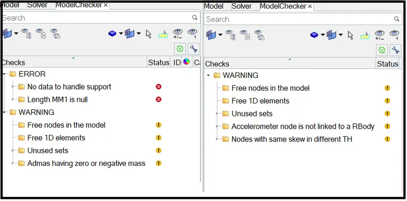
All error are fixed by auto fix option.
RUN THE ANALYSIS:
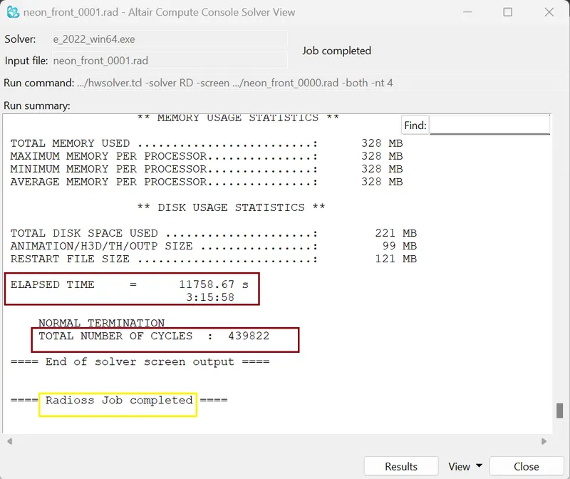
Analysis >> Radioss >> Input File: (File Location) >> Hit Radioss
The input file is the same Started file (contains model information) that we had just imported.

After 7hrs our simulation is completed. it will show JOB IS COMPLETED.
- Checking energy error and mass error:
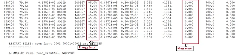
we need to check the output of simulation in 0001.out file
- Condition for acceptable result
- The error {Energy} must be less than – 15 % at the end of computation (0% for a good model setup).
- The error {mass} must be less than 2%.
So, from output data our both the condition is satisfy we go for plots.
Energy and Force Graphs:
The tools to plot the graph are available on Hyper Mesh name as Hypergraph.
- Energy Graphs:
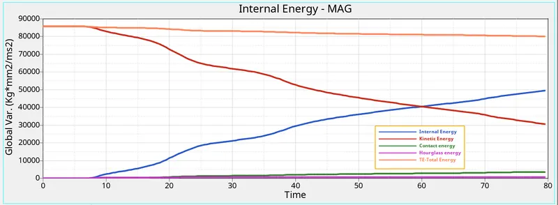
As the vehicle is moving with a certain velocity (Say 15.646 mm/ms for the Model), the initial kinetic Energy will be High (Refer to Above Graph). Once the car is hit by the rigid wall, the vehicle starts deforming results in absorbing the Surrounding Energy and stored it. Thus, internal Energy starts increasing. At the Maximum deformation, the Velocity will become Zero and thus the kinetic energy will also be dropping down to zero resulting there is no energy to absorb in the system. Thus, Internal Energy Remains Constant thereafter.
The above graph shows that the Hourglass energy is almost negligible since we have used improved integrated element formulation (QEPH).
SECTIONAL FORCES:
1.) Sectional force in the rails at location of indicated node 174247.
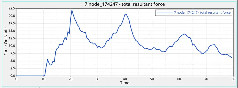
The force at particular location is 22.3 kN.
2.) Force experienced in the bumper
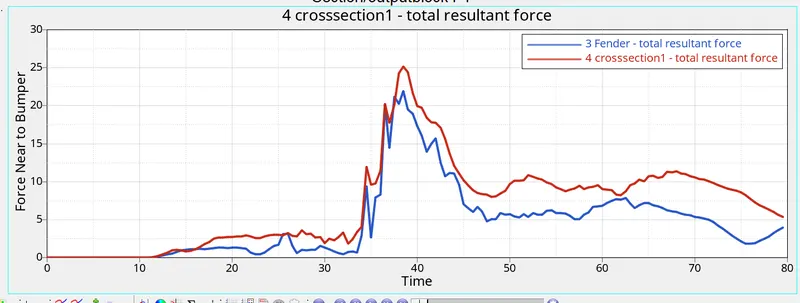
The force at Bumper is 25.1925 kN. During the simulation, the Bumper will come into contact with the rigid ball first hence it will experience the maximum force. The Bumper will absorb some force and transmit the rest to the Rails and other connected components.
3.) Forces experienced in the A PILLARS
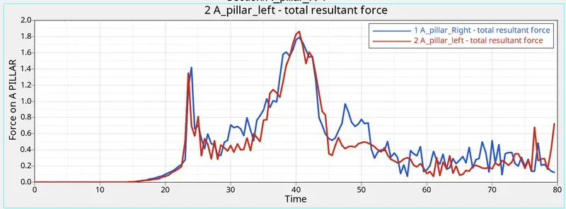
The maximum cross-sectional force at Left A-Pillar is 1.8661 kN whereas the maximum cross-sectional force at Right A-Pillar is 1.7882 kN. when the car hits the rigid wall, there will be some amount of force coming into the A-pillar at both sides. These forces coming to the A-pillar are nothing but the force transmitted from the rail and the Bumper. The force flowing into the LH and RH of the A-pillars will not be equal and hence the deformation of the elements will differ accordingly.
During a frontal crash, the sectional force reaching the A-pillars is coming in from the rails and shotgun, hence the force at the A-pillars will be less when compared to the front sections. When the compressive force between the wall and car is maximum, the rail and shotgun get in contact with the rigid wall which causes the shotgun and rail to exert more force. This force then propagates to the A-pillars and hence the force reaching the A-pillar increases again.
4.) Forces experienced on the RAIL
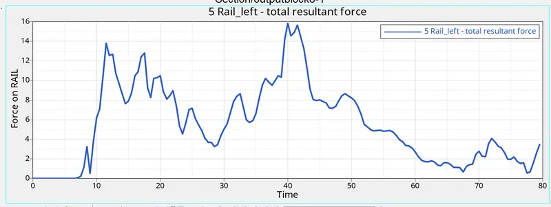
The maximum cross-sectional force at Left Rail is 15.8465 k N. The force acting on the rail is the force transmitted by the bumper during the crash. The force transmitted by the bumper to the rail is not equal as some of the force will be absorbed by the Bumper resulting in deformation.
- ACCELEROMETER
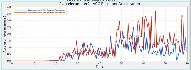
As we all know that an Acceleration is the rate of change of velocity. To measure the deceleration, we have placed the accelerometer near the Rocker of B-Pillar on both sides.
Once the Car hits the rigid wall with the initial velocity, the acceleration of the vehicle during the crash is not constant across the structure. The front of the vehicle slows down immediately as it hits the rigid wall, while the rest of the structure decelerates at a slower rate as seen in the graph. As seen from the graph there is a sudden increase in the acceleration, this might be because of some vibration that occurs during the crash with respect to the point where the accelerometer is placed.
INTRUSION
- for node 66695
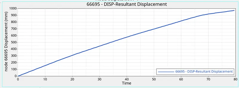
For accurate displacement result we need to subtract (distance between node and moving skew)
- The maximum value from this curve is 972.4246 mm
- Distance between node and moving skew is 814.813 mm
- So, actual Displacement is (972.4246-814.813) = 157.6116 mm
- for node 66244
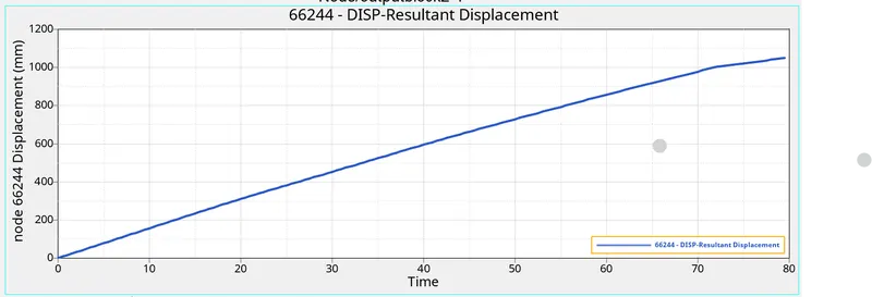
For accurate displacement result we need to subtract (distance between node and moving skew)
- The maximum value from this curve is 1051.1872 mm
- Distance between node and moving skew is 833.696 mm
- So, actual Displacement is (1051.1872- 833.696) = 217.49 mm
Here we can observe that the node 66244 displace more as compare to node 66695.
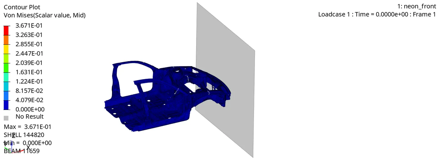
- Von-mises stress
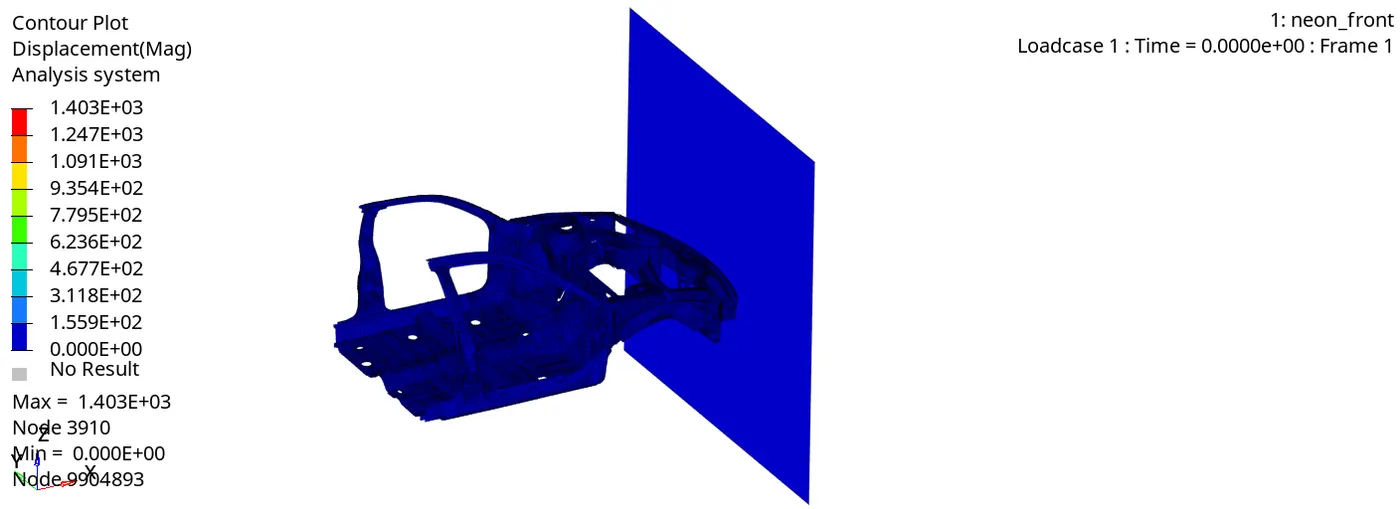
- Displacement
CONCLUSION:
Here The given model was simulated for the frontal crash using RADIOSS and the results obtained were validated. The graphical results were plotted for all the test cases. From the simulation, it can be observed that there was minimum deformation in the cabin seat area.
Learning Outcome:
Here we have learned
- How to set up a frontal crash test.
- How the rigid wall interface works and can lead to incompatible Kinematic conditions.
- How Sectional forces are generated.
- How the distribution of forces among the components during a frontal crash.
- How some components are designed to deform in such a way to ensure the safety of the passengers inside the cabin.
- How to Debugging errors in order to get the right results.
***********************************************************************************************************************************************************************************************************************************************************************END
Thanks & regards,
DEVESH KASHYAP