Assignment 2-RADIOSS Engine File Editing & 3D Meshing Challenge
Questions:1 Check the material properties of the rail component and calculate the speed of sound in steel rail ?
ANSWER: from the given 0000.rad file we can get the material properties of steel rail
#RADIOSS STARTER
##========================================================================================
##
## Radioss Input Deck Generated by HyperMesh Version : 2017.0.0.24
## Generated using HyperMesh-Radioss Template Version : 2017
## Date: 03-10-2018 Time: 20:43:56
##
##========================================================================================
##
##--------------------------------------------------------------------------------------------------
#---1----|----2----|----3----|----4----|----5----|----6----|----7----|----8----|----9----|---10----|
##
/BEGIN
FIRST_RUN
120 0
g mm ms
g mm ms
##
##--------------------------------------------------------------------------------------------------
## Title
##--------------------------------------------------------------------------------------------------
/TITLE
First Run of RADIOSS
##--------------------------------------------------------------------------------------------------
## Material Law No 2. JOHNSON-COOK / ZERILLI-ARMSTRONG ELASTOPLASTIC
##--------------------------------------------------------------------------------------------------
#---1----|----2----|----3----|----4----|----5----|----6----|----7----|----8----|----9----|---10----|
#- 2. MATERIALS:
#---1----|----2----|----3----|----4----|----5----|----6----|----7----|----8----|----9----|---10----|
# E Nu
# a b n EPS_max SIG_max0
# c EPS_DOT_0 ICC Fsmooth F_cut
# m T_melt rhoC_p T_r
/MAT/PLAS_JOHNS/1
Steel
# RHO_I
0.0078 0.0
210000.0 0.29
180.0 450.0 0.5 0.0 350.0
0.0 0.0 0 0 0.0
0.0 0.0 0.0 0.0
From this we get
E (Modulus of Elasticity) = 210000 MPa or N/mm^2 .
rho (Density) = 0.0078 g/mm^3
speed of sound in steel rail (C) = sqrt(E/rho)
E – Modulus of Elasticity.
Rho – Density.
--> C = sqrt. (210000/0.0078)
--> C = Sqrt. (26923076.92)
--> C = 5188.7452 mm/ms
speed of sound in steel rail= 5188.74 mm/ms.
Questions:2 The length of the rail is about 1000 mm.calculate the time takes for a shock wave to travel from one end of the rail to the other.
ANSWER:
Here Shock wave means sound wave.
- We have speed of Sound/shock wave = 5188.7452 mm/ms.
- And We have distance of rail is about 1000 mm.
Time taken by the Shock wave = 1000/5188.7452
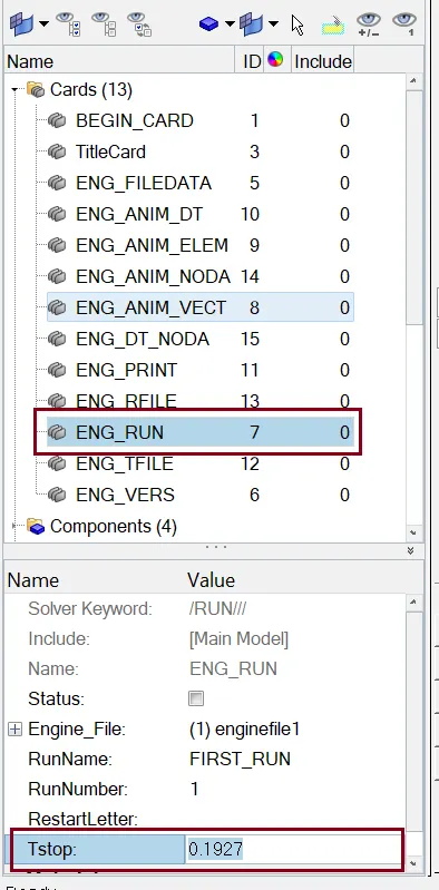
Time taken by shock wave is = 0.1927 ms.
Questions:3 Time for sound to travel length of rail ?
ANSWER:
- We have speed of Sound = 5188.7452 mm/ms.
- We have rail distance is about 1000 mm.
Time taken by the Sound to travel length of rail = 1000/5188.7452
Time taken by Sound is = 0.1927 ms.
Questions:4 Edit the engine file so that the stress wave can be monitored, moving from one end of the rail to the other during impact -this will require a termination time equal to the time it takes for the sound to travel the length of the rail.
ANSWER:
Here very first we import the file, we will choose our user profile as RADIOSS. Then we will import the starter file in RADIOSS. In our case, the given file name is FIRST_RUN_0000.rad, we will import this file under Import Solver Deck browser as shown below,
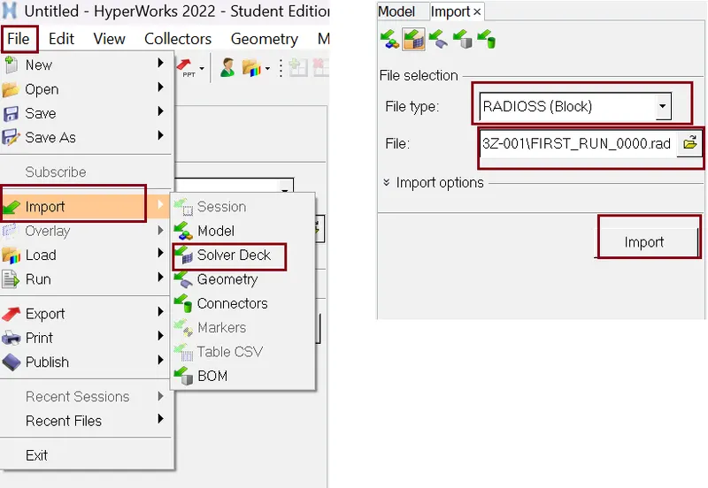
file edited according to the above calculated values
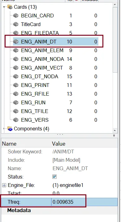
Questions:5 Set the frequency of animation output to a time that will give 20 animation steps.
ANSWER:
T {freq.} = Time Stop/No. of frame
= 0.1927/20
= 0.009635
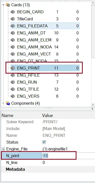
Questions:6 Change /print -10.
ANSWER:
Questions:7 3D meshing tetra mesh and hex mesh
ANSWER:
3D tetra mesh
OBJECTIVE:
- To Create a Tera mesh for Housing component with the
following quality criteria.
- Element Generation Method: 2D to 3D Conversion
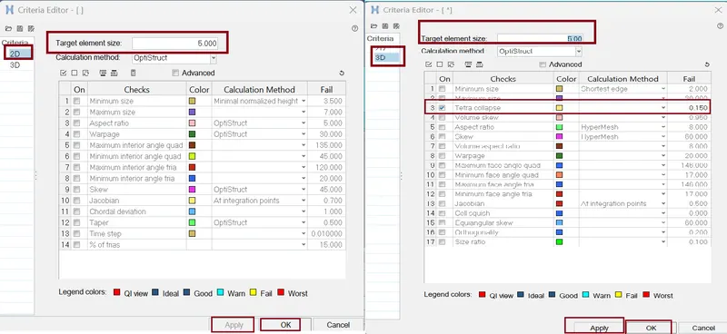
- Elements sizes: Target- 5 Units,
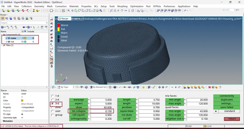
- Tet collapse: 0.15
PROCEDURE/STEPS: -
- import cad geometry file
Here we have Housing component we need to open the model in Hyper mesh GUI.
Command: File >> Import >> Model >> Locate the file directory (as per given figure) >> hit Open >> hit Import.
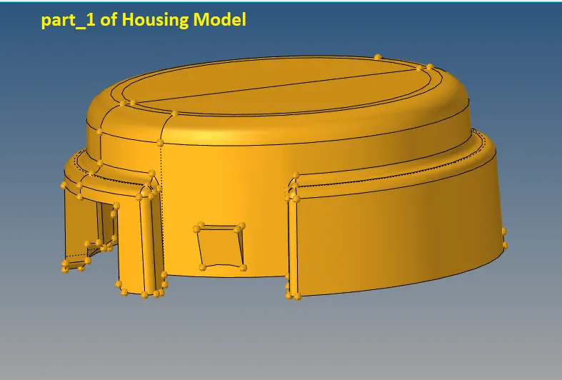
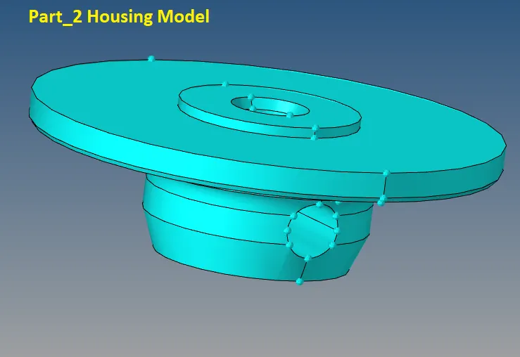
- Geometry clean-up
Perform manual defeaturing for the areas where the elements might fail for quality. And also we Remove the unnecessary fillets, toggle unwanted edges.
- Quality Criteria setting:
Now we want to start surface Meshing on the Component. Before meshing we need to set quality criteria.
Command for setting Quality Criteria: Preference >> Criteria file setting >> Edit the card as per figure below >> hit Apply >> ok.
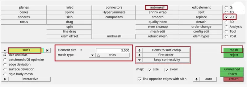
- 2D meshing:
Now we start the surfaces meshing for this we use....
Command: 2D >> automesh >> edit the tab as per figure below >> select the surface >> hit mesh >> hit middle mouse click. We can also access this tab by pressing F12 key.
- 3D Mesh or Volume Mesh
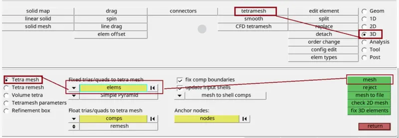
Now we Perform 3D tetra Mesh using 2D tria elements.
Command: 3D >> tetramesh >> select all the elements >> mesh.
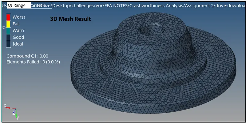
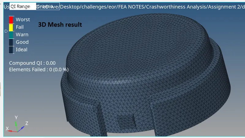
- 3D Mesh Result:
- Checking for Quality
For checking quality failing Element we use F10 key. and check only for tetcollapse.
3D Hexa mesh
OBJECTIVE:
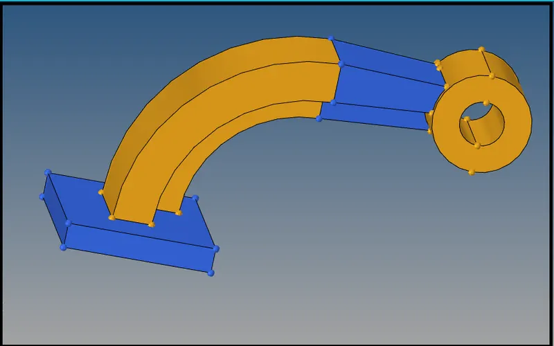
- To perform hexa Meshing on the given Model (arm_bracket) Model.
PROCEDURE/STEPS: -
- import cad geometry file
Here we have arm_bracket Model, we need to open the model in Hyper mesh GUI.
Command: File >> Import >> Model >> Locate the file directory (as per given figure) >> hit Open >> hit Import.
- Geometry clean-up
Perform manual defeaturing for the areas where the elements might fail for quality. And also we Remove the unnecessary fillets, toggle unwanted edges.
There were no surface defects in this model so, we will proceed for meshing.
- Meshing:
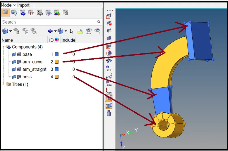
Here we have four components in this model which are base, arm curve, arm straight and boss. So, we will mesh them one by one
1.) Base
- Very first We will make Base as our current component and hide all other components.
- we will create 2D mesh on its top surface by selecting the mesh type as mixed.
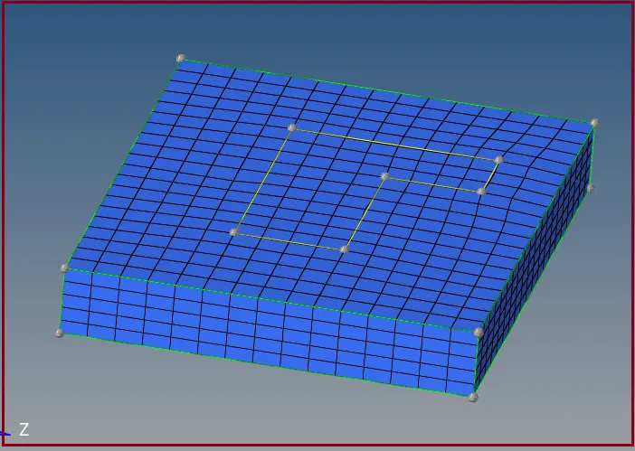
- After that we convert it to 3D hexa elements, we will offset these elements.

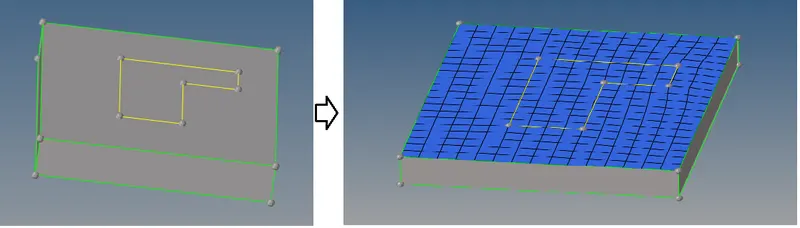
3D Mesh
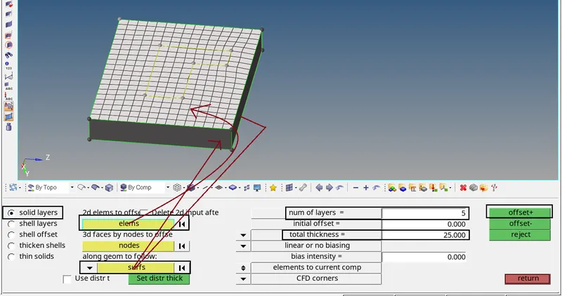
After creation of Shell mesh we use Command: 3D >> elem offset >> Solid layer >> select element and edit the tab as figure below >> hit offset + .
Mesh result for Base
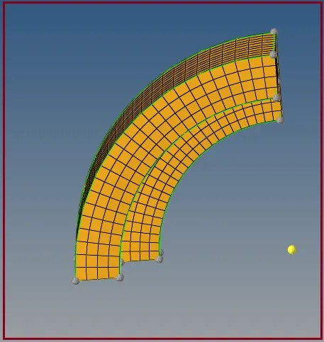
2.) arm_curve
- Similarly, as previous make it as our current component and hide all other components.
- The geometry for this component is like a partial Torus. So, we can spin the elements to obtain 3D hexa mesh.
Steps
- hide hex element (by the help of Mask Command)
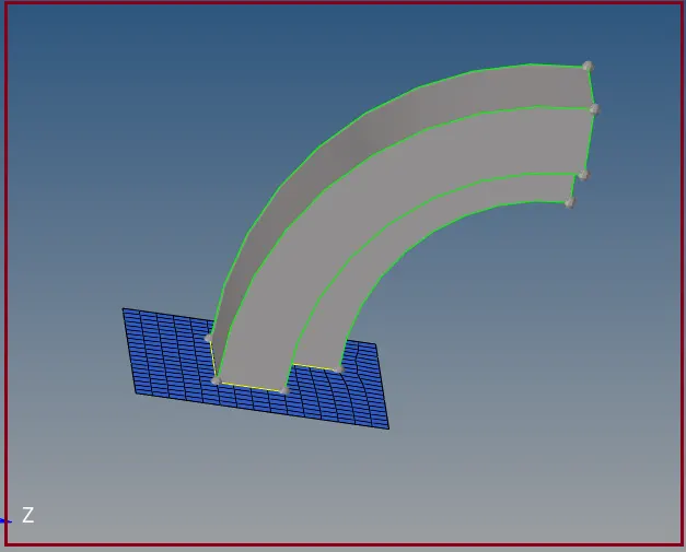
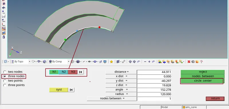
- Create centre point for the arm_curve
Command: F4 >> three nodes >> select three nodes on the curve >> circle certe.
- Now we spin the elems Command: 3D >> Spin >> Spin element >> edit the tab as per figure given below.
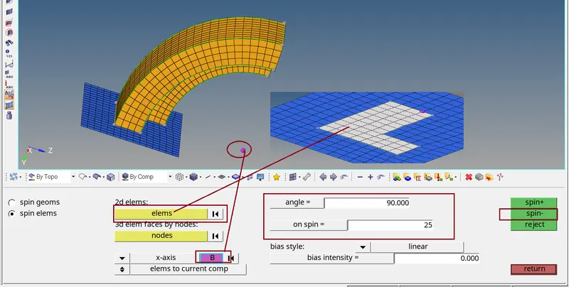
Mesh result for arm_curve
3.) arm_straight
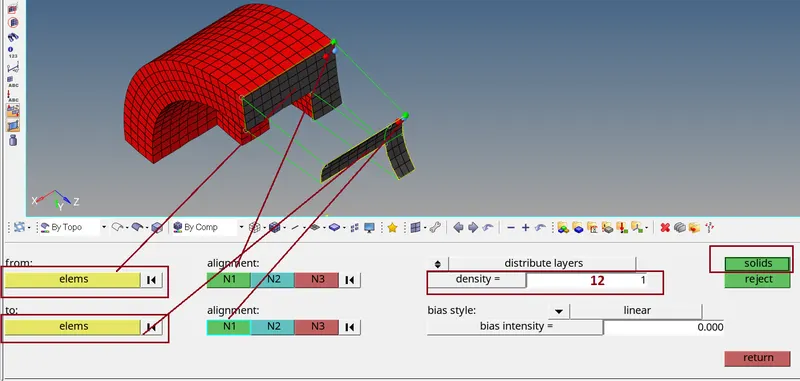
- For meshing the arm straight component, We use Command: 3D >> linear solid option.
- Here we try mesh each end by 2D element and join the same in this method.
- Already one end of arm straight component is meshed by hex element, to extract 2d element from hex element, go to tools >> faces extract faces option.
- One end of the component will have 2D elements, mesh the other end with same number of elements to avoid Penta elements.
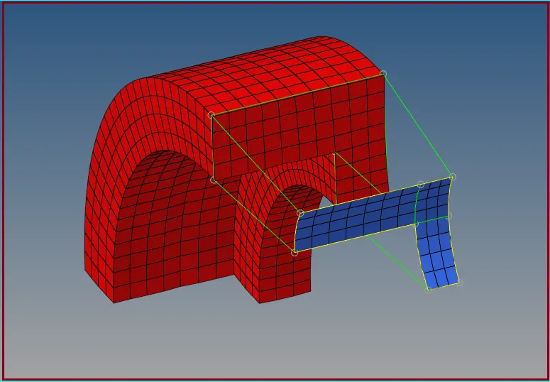
for 3D solid
Command: 3D >> linear solid option.
Mesh Result:
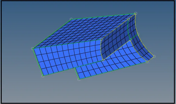
4.) Boss
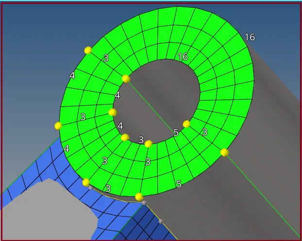
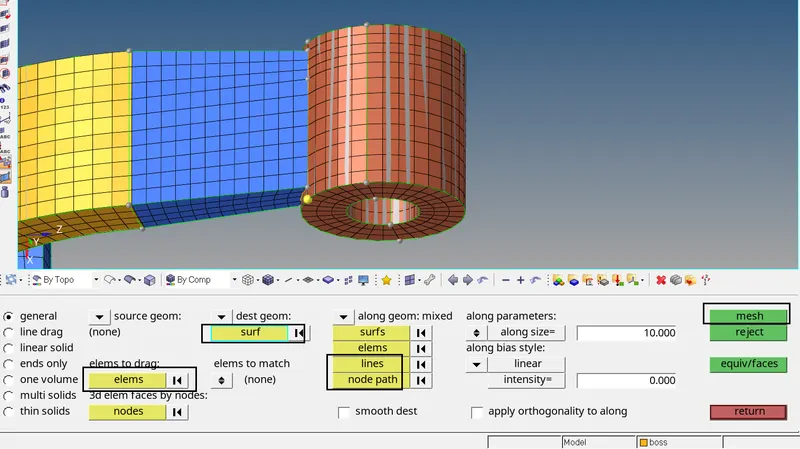
- To mesh the boss component we will be using Solid map option
- Mesh the boss one side and solid map the element to the ither end by nodes
2D Mesh
3D mesh
Final result:
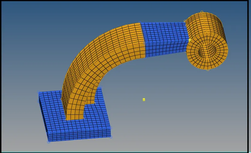
- After meshing all the components by hexa elements we have to delete all the 2D elements present in the model
- Go to delete option select elements by config option and select quad4 element, now all the 2 element will be deleted
CONCLUSION:
Here we understand
- How to read input RADIOSS file
- How to calculate speed of sound in different material, frequency, time step
- How import the RADIOSS solver deck file and feed the value
- How to export the file in. rad format
- How to do Hex meshing.
***********************************************************************************************************************************************************************************************************************************************************************END