Week 4-1D Element Creation Challenge
AIM: To extract the Mid plane and mesh the given component and also create 1D element Connection.
OBJECTIVE:
- To extract the mid plane.
- To Mesh the component.
- To make 1D connection as per given location.
THEORY:-
1D ELEMENTS: One of the dimensions is very large as compare to the other two dimension. All line elements, whether straight or curved, are called 1D element in which they have translational and rotational displacement functions.
Element type – Rod, bar, beam, pipe, etc.
Example- Long shafts, beams, pin joint etc.
PROCEDURE/ STEPS:
- Importing the CAD Geometry
Very first we need to import the CAD Geometry into the workspace and delete the wireframe.
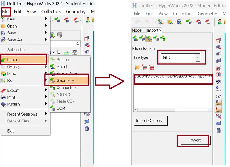
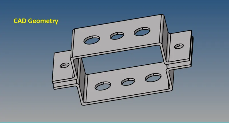
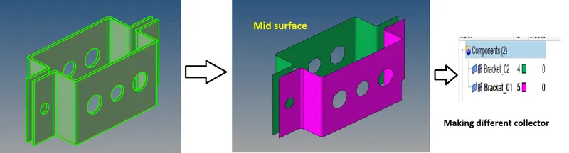
- Next step is Creating the mid surface for this CAD Geometry.
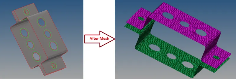
For this we use Command: Geom >> Mid surface >> edit the tab as per figure below >> hit extract.

Meshing the component
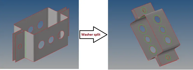
Washer split
Before meshing we need to create washer splits near the hole region for a smooth mesh.
For this we use Command: Geom >> quick edit >> washer split >> Edit the tab as per figure below >> right click over the hole edge.

Generate the mesh with the help of Command: 2D >> Edit the tab as per the figure below >> hit mesh.

and we mesh
Connection:
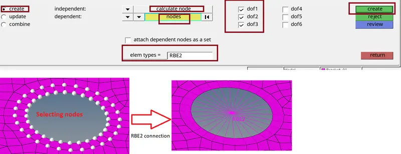
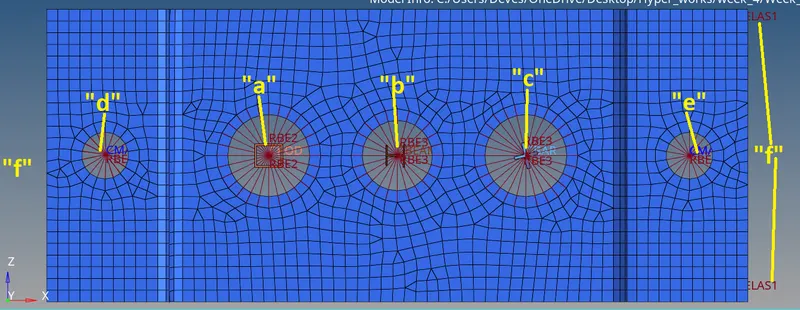
AT location “a”
Very first we generate RBE2 connection at location “a” for this we use Command: 1D >> rigids >> edit the tab as figure below >> select the node >> hit create.
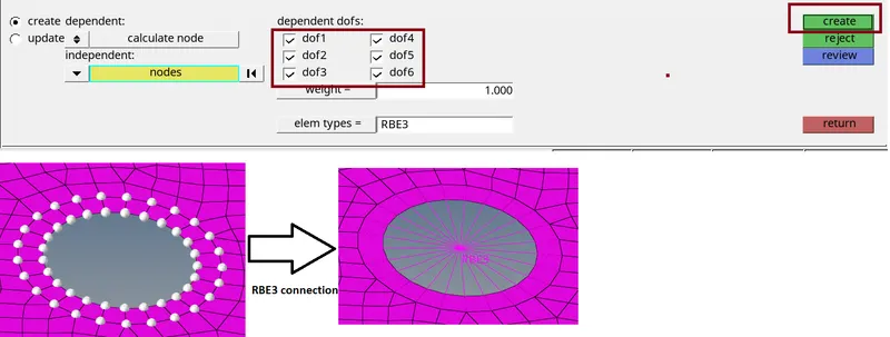
AT Location "b"
We create RBE3 connection here for this we use Command:1D >> RBE3 >> edit the tab as figure below >> select the node >> hit create.
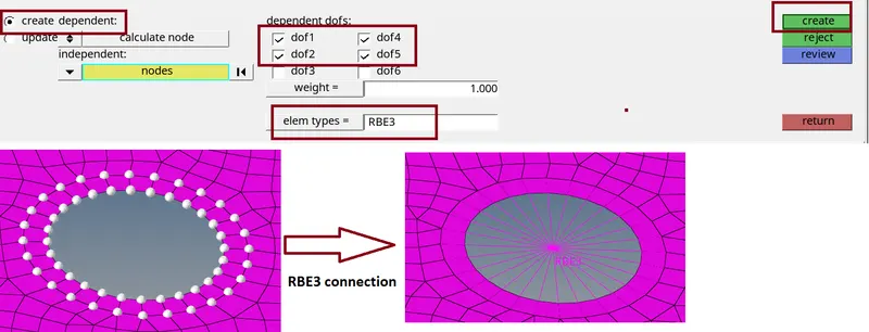
Similarly at location "c"
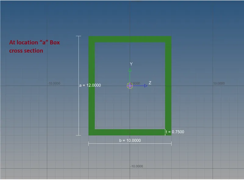
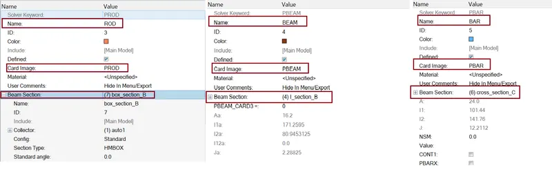
Now we create cross sections for Rod at location “a”, Beam at location “b” and Bar at location “c” .
1.) Rod:
Given data:
a. Rod element:- Translational DOF should be Constrained with RBE2 link
Cross-Section: BOX- Dimension a= 12 mm
dimension b=10 mm
Thickness t= 0.75 mm
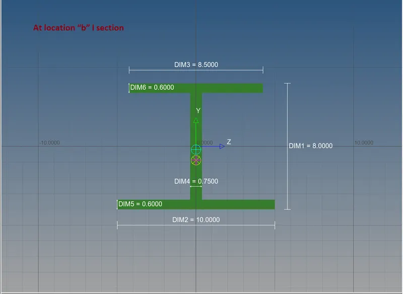
b. Beam element:- All DOF should be constrained with RBE3 link
Cross-Section: I Section- Dimension a= 8 mm
Dimension b= 10 mm
Dimension c= 8.5 mm
Thickness t1= 0.75 mm
Thickness t2= .6 mm
Thickness t3= .6 mm
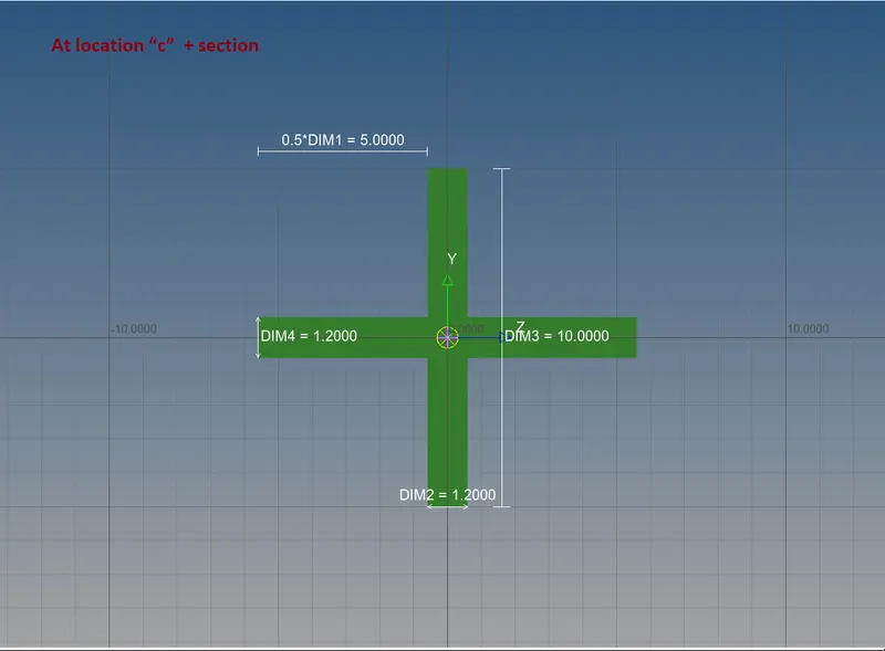
3.) BAR:
Given data:Constrain only x and y DOFs With RBE3 link
Cross-section: X section- Dimension DIM1= 5 mm
Thickness DIM2= 1.2 mm
Dimension DIM3= 10 mm
Thickness DIM4= 1.2mm
Now cross sections are created, we need to create property for Rod, Beam and Bar with property cards such as PROD, PBEAM and PBAR.
DEFINING NODE, ASSIGNING ELEMENT TYPE AND PROPERTY
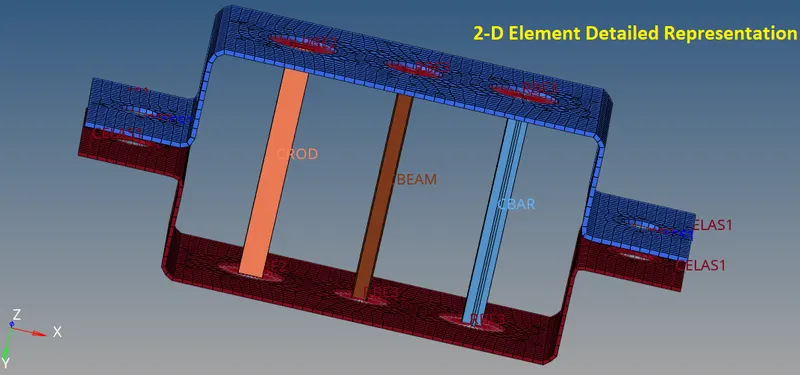
- For Rod we need to select 2 RBE2 nodes one is upper side and second one is down side
Command: 1D >> rods >> edit the tab as per figure below >> select node A and B >> CROD is generated.

- For beam we need to select 2 RBE3 nodes one is upper side and second one is down side.
Command: 1D >> bars >> edit the tab as per figure below >> select node A and B >> CBEM is generated
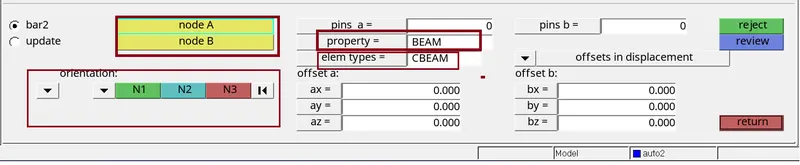
- similarly for BAR we need to select 2 RBE3 nodes one is upper side and second one is down side.
Command: 1D >> bars >> edit the tab as per figure below >> select node A and B >> CBAR is generated.

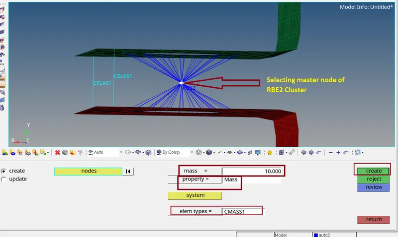
- At location “d” and “e” we need to create RBE2 Element associated with Mass of magnitude 10 unit.
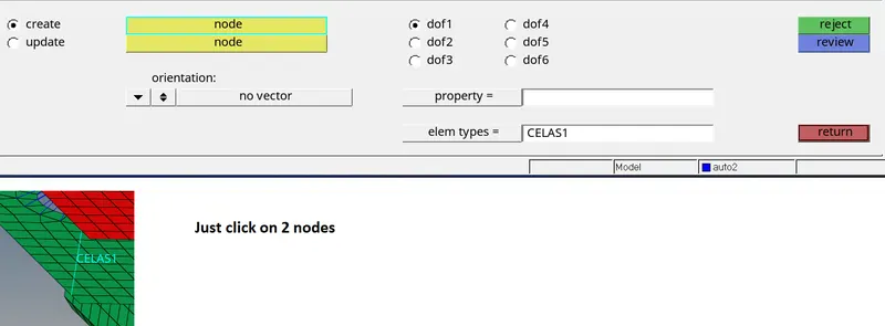
- At location "f" we need to create spring.
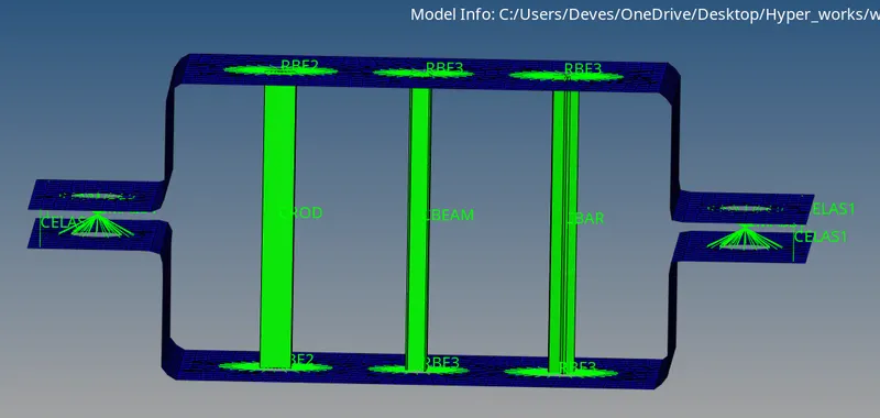
- Final view of our component is
CONCLUSION:
- Here we Extracted the mid-surface for the given component and mesh the mid surface.
- After that Holes has been connected with RBE2 & RBE3 elements.
- Then we created CROD, CBEAM, CBAR 1D elements with their DOF constrained according to the data given.
- Assigned Cross-section and property to the 1D elements
- Created Solid representations of 1D Element.