Week 5 Sphere pressing on a plate
Aim- To perform the Structure analysis/simulation for sphere pressing on a plate.
OBJECTIVE:
To perform the analysis to simulate a sphere pressing on a plate by using Structural steel for both sphere and plate but the material for the plate must be Non-Linear. Press the sphere onto plate 4mm downwards and retract it.
THEORY:
Plastic deformation
Plastic deformation is a process that permanently changes the shape of a material by applying external forces that exceed its elastic limit. When a material is subjected to mechanical forces, it deforms elastically up to a certain point, after which it undergoes plastic deformation. In this process, the material is permanently deformed and cannot return to its original shape.
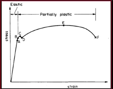
Plastic deformation occurs in several ways, including compression, tension, bending, and shearing. In compression, the material is squeezed together, reducing its length and increasing its width. In tension, the material is stretched, increasing its length and reducing its width. Bending occurs when a force is applied perpendicular to the plane of the material, causing it to curve. Shearing happens when a force is applied parallel to the plane of the material, causing it to deform in a sliding motion.
The plastic deformation of a material can be influenced by various factors, including the type of material, its temperature, the magnitude and direction of the applied forces, and the rate at which the forces are applied. Understanding plastic deformation is important in many engineering applications, such as the design of materials and structures that can withstand mechanical stresses and strains.
ANALYSIS SETUP:
Here we will start our work Structural Analysis for Plastic deformation of a Nonlinear Plate due to impact of Sphere body.
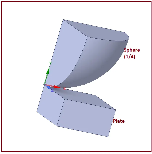
We will take a portion of the Plate and a Sphere which can be taken as Symmetric geometry for saving computation time and calculation on the whole body.
- Given Geometry:
Mesh:
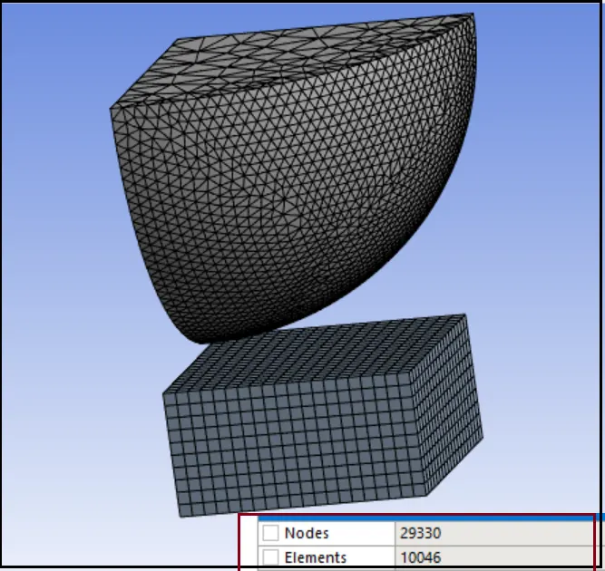
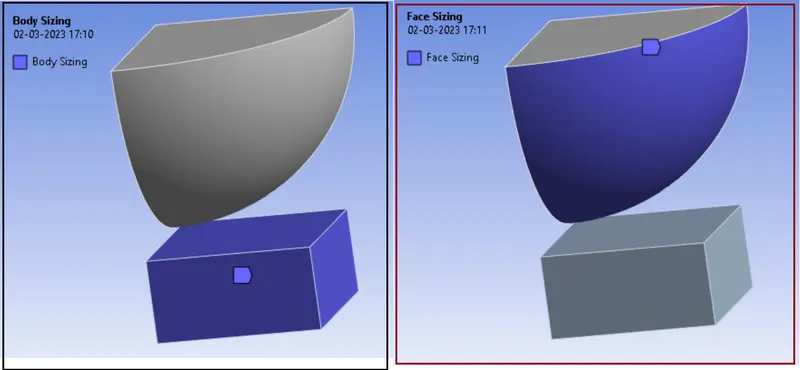
Mesh Details:
- Global Element Size: Default
- Body Sizing: Plate
- Element Size = 0.5 mm
- Face Sizing: Contact Faces of Sphere
- Element Size = 0.5 mm
Material:
Material Specifications for Plate:
{Structural Steel NL}
- Density: 7850 Kg/m3
- Young’s Modulus: 2E+05 MPa
- Poisson’s Ratio: 0.3
- Yield Strength: 250 MPa
- Tangent Modulus: 1450 MPa
Material Specifications for Plate:
{Structural Steel}
- Density: 7850 Kg/m3
- Young’s Modulus: 2E+05 MPa
- Poisson’s Ratio: 0.3
- Tensile Yield Strength: 250 MPa
- Compressive Yield Strength: 250 MPa
- Tensile Ultimate Strength: 460 MPa
Initial steps
- Import model in Static Structural named as “Skill_Lync_Sphere_pressing on plate.STEP” in Geometry section.
- Then go to Mechanical model section.
- Check or Rename the Parts of the setup as Sphere and Plate as shown in above geometry image.
- Sphere material is by default as Structural Steel.
- Assign Structural Steel NL material to Plate.
Connections:
Very first we need to Delete automatically created contacts and create new contacts as given below:
Contact:
Contact Body = Sphere
Target Body = Plate
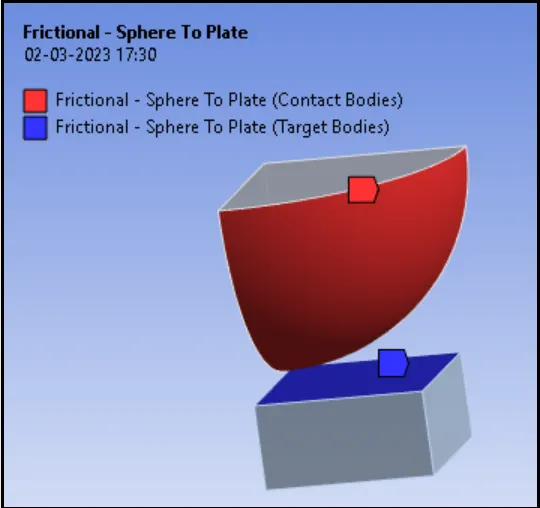
Here one face of the Sphere is set to Contact face and one face of the Plate is set to Target Face.
Settings we need to edit for the Contacts.
Type: Frictional
Friction Coefficient: 0.74
Boundary Conditions settings:
Our next step is creating Boundary Conditions:
Analysis Settings:
No. of Steps: 2
Solver Type: Direct
Large Deflection: ON
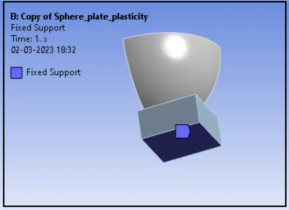
Fixed Support:
Apply Fixed Support to restrict movement of plate as given below:
Displacement:
we have to give displacements in order to move the sphere in Y direction.
Direction: -Y (Negative)
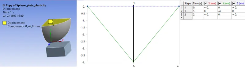
Give Displacement to Sphere from 0 to -4 and retract it again to -4 in 0.
SOLUTION
After giving proper boundary conditions, create desired solutions for output results. Create Solutions for
- Equivalent Stress for Plate
- Directional Deformation in Y-axis for Whole Setup
- Total Deformation
- Equivalent Strain for Plate
- Equivalent Plastic Strain for Plate
- Equivalent Strain for Sphere
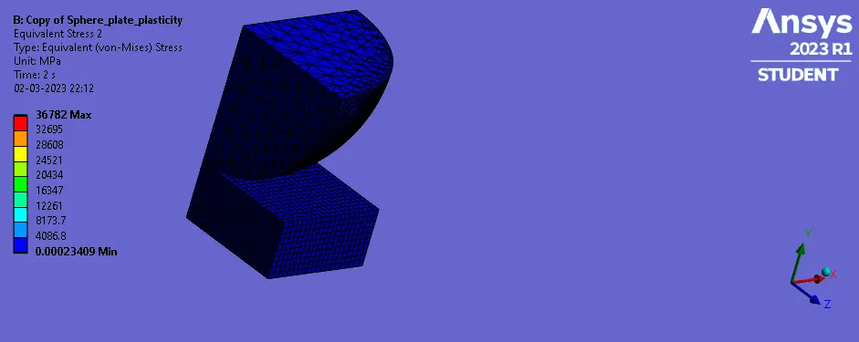
- Stress for Plate:
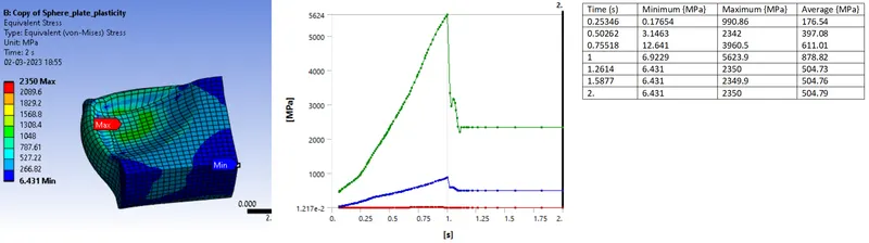
Here We can observe that the induced stress exceeds the yield point limit.
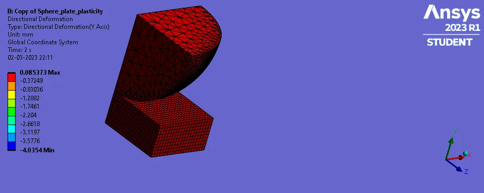
- Directional Deformation in Y-axis for Whole Setup
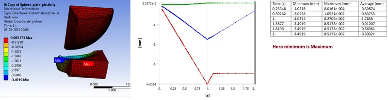
from above image.
From above image we can observe the displacement of sphere occurs up to step 1 and then it retracts.
We can see from the plot that at the end of step 1, displacement of sphere becomes 4 mm which is maximum.
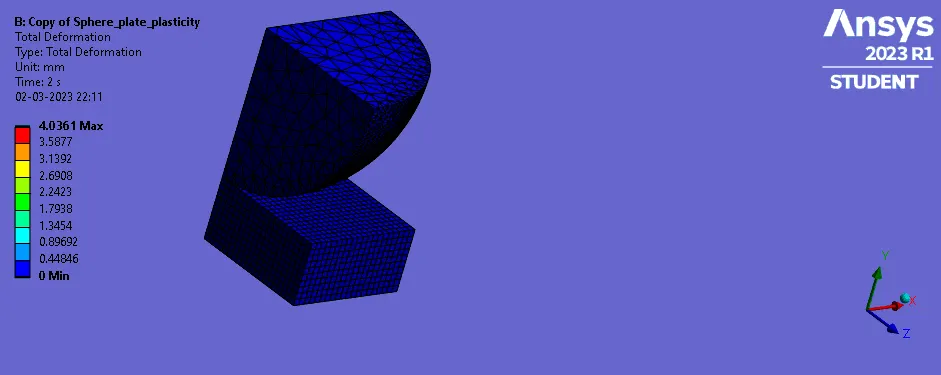
- Total Deformation
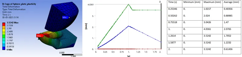
In Above image is evidence of the Plastic deformation.
We can see the deformation on the plate at the location of hitting of sphere.
Also from the plot, we can see that from step 2, deformation becomes stable. It means there is a permanent deformation on plate.
- Equivalent Strain for Plate
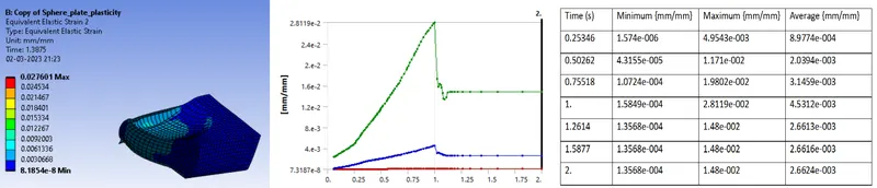
Here we can see that very low stain in elastic region.
- Equivalent Plastic Strain for Plate
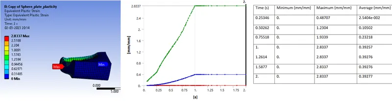
On ramping of sphere on plate, Plastic or residual strain reaches up to 2.8337 mm and becomes stable.
- Equivalent Strain for Sphere
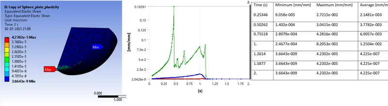
Here we observe that the material of sphere is structural steel. So maximum value of strain which is elastic in nature and very low compared to Plate.
CONCLUSION:
- Here in all images and plots, we can observe displacement of Sphere in Y direction and it hits a Plate and retracts.
- When the applied load crosses the elastic limit, plastic deformation occurs. It also can be described by the above contours and plots of Plastic strain.
- in elastic deformation, when load is removed, material regains its shape. But in our case, it is not regaining its shape. It means there is Plastic Deformation.
- Structural analysis shows how materials, such as non-linear structural steel, perform under displacement loading. From the results of a structural analysis, a design engineer can make a more informed performance prediction of the component or product being simulated and improve the design accordingly.
-----------------------------------------------------------------------------------------------------------------------------------------------------------------------------------------------------------------------------
ANIMATION...
Stress
TOTAL Deformation
Directional Deformation
*********************************************************************************************************************************************************************************END
Here Due to large size of the Ansys file, I have attached a link for the Ansys .wbpz file in below "Model Browse" area.
Kindly find attached link via word document.
Thanks & regards,
Devesh kashyap