Week 2 Bevel Gear Challenge
AIM: To perform Grid dependency test over Bevel gear.
OBJECTIVE:
- To Perform static structural analysis to find out Equivalent stress, Total deformation and Equivalent strain.
- To perform grid dependency test Using three different sizes of mesh 4, 5 and 6 mm .
- To Comparing the results (Equivalent stress, Total deformation and Equivalent strain).
THEORY:
A bevel gear is a type of gear used to transmit power and torque between two shafts that are not parallel to each other. It is designed to operate at an angle, typically at 90 degrees, to transmit motion and power between two intersecting shafts. Bevel gears have a conical shape with teeth cut along the conical surface. The teeth of bevel gears are angled, which allows them to mesh together and transfer rotational force between two intersecting shafts at a right angle. Bevel gears are commonly used in a variety of applications, including in automobiles, machine tools, marine equipment, and other mechanical systems.
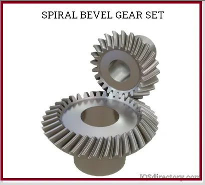
There are several types of bevel gears, including straight bevel gears, spiral bevel gears, and hypoid gears. Straight bevel gears have straight teeth that are cut at an angle to the gear's axis. Spiral bevel gears have curved teeth that gradually transition from one end of the gear to the other. Hypoid gears have a complex curved shape that allows them to transmit power between non-intersecting shafts.Bevel gears are designed to operate at specific angles and speeds, and must be carefully selected and installed to ensure optimal performance and reliability in a given application.
Grid Dependency Test:
- In ANSYS, a grid dependency test is a method used to determine the appropriate mesh size for a simulation. The grid dependency test involves performing the simulation multiple times, each time using a different mesh size, and comparing the results to determine the impact of the mesh size on the accuracy of the simulation.
- The grid dependency test is performed by setting up a simulation with a given mesh size, running the simulation, and then repeating the simulation with a finer mesh size. The process is repeated until the results converge and do not significantly change with further refinement of the mesh.
- The results are then compared to determine the appropriate mesh size for the simulation. If the results show significant changes with each refinement of the mesh, the mesh size needs to be further refined. On the other hand, if the results do not change significantly with further refinement, then the mesh size can be considered appropriate for the simulation.
- The grid dependency test is important because the accuracy of a simulation depends on the quality of the mesh used. A mesh that is too coarse may lead to inaccurate results, while a mesh that is too fine may result in longer simulation times and higher computational costs without any significant improvement in accuracy. Therefore, the grid dependency test helps to determine the appropriate mesh size to balance accuracy and computational efficiency.
PROCEDURE/STEPS: -
- Insert the given geometry
We start our work Open Static Structural and in SpaceClaim, import geometry named as “Skill_Lync_Bevel_Gear.igs”.
After importing geometry, we can see unwanted volume in gear. So, for removing it cut out the Diameter 45 mm from Big Gear and Diameter 25 mm from Small Gear with help of “MOVE” option as shown below.
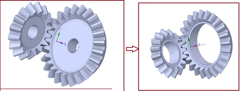
After finalizing geometry, go to the Mesh.
- Mesh
Here we Create Mesh with global mesh size 6 mm.
Give “face Sizing” and select all faces of both gears and give element size = 1.75mm.
After giving values generate mesh as shown below:
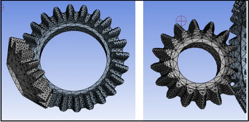
Global Mesh size = 6 mm
Face sizing = 1.75 mm
No. of Nodes: 26415
No. of Elements: 14247
- Connections Details:
- Contacts: Contact Body = Small Gear (Faces = 16)
- Target Body = Big Gear (Faces = 24)
- Type: Frictional
- Behavior = Symmetric
- Formulation = Augmented Lagrange
- Interface Treatment: Adjust to Touch
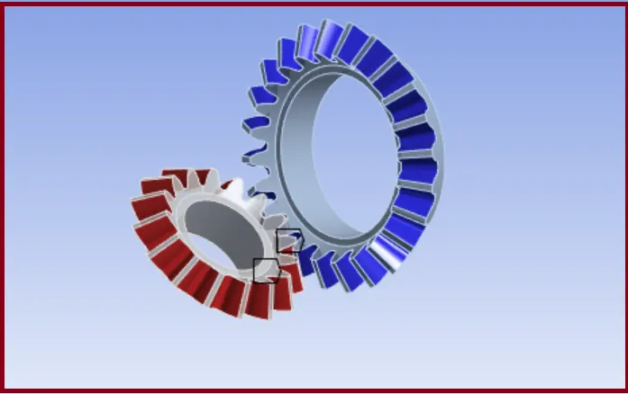
Joints
Joints: Joint 1
- Connection Type: Body-Ground
- Type: Revolute
- Body: Biger Bevel Gear
Joint 2
- Connection Type: Body-Ground
- Type: Revolute
- Body: Small Bevel Gear
- Material – Structural steel
- Setting Boundary Conditions:
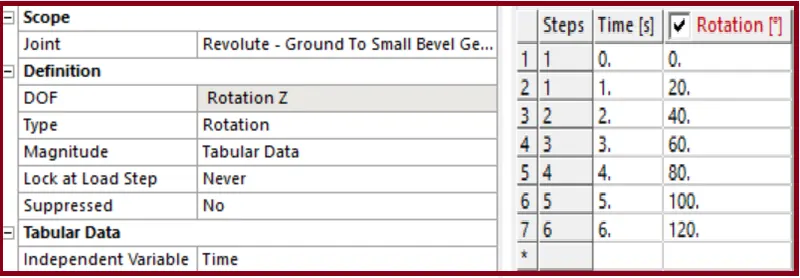
Here we are going to look at contact forces, traces and stress developed for revolution of gear. So for 120 degree angle, In analysis settings give values as given below:
- No. of Steps = 6
- Auto Time stepping = ON
- Defined by = Time
- Initial Time Step = 0.1 s
- Minimum Time Step = 0.05 s
- Maximum Time Step = 0.2 s
- Select “Large Deflection on”.
Other Boundary conditions for joints are as given below:
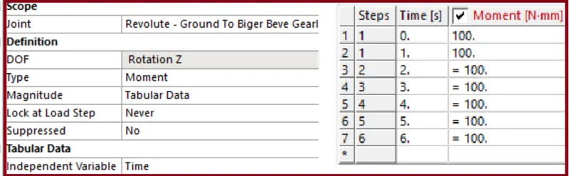
Joint Load: 1st one
Joint: Revolute – Ground to Biger Bevel Gear
Type: Moment
Magnitude: Tabular Data
Joint Load: 2nd one
Joint: Revolute – Ground to Small_Gear
Type: Rotation
Magnitude: Tabular Data
SOLUTION:
Now the time is to get solution After giving proper boundary conditions, create desired for output results.
Create Solutions for “Equivalent (Von Mises) Stress”, “Equivalent (Von Mises) Strain” and “Total Deformation”.
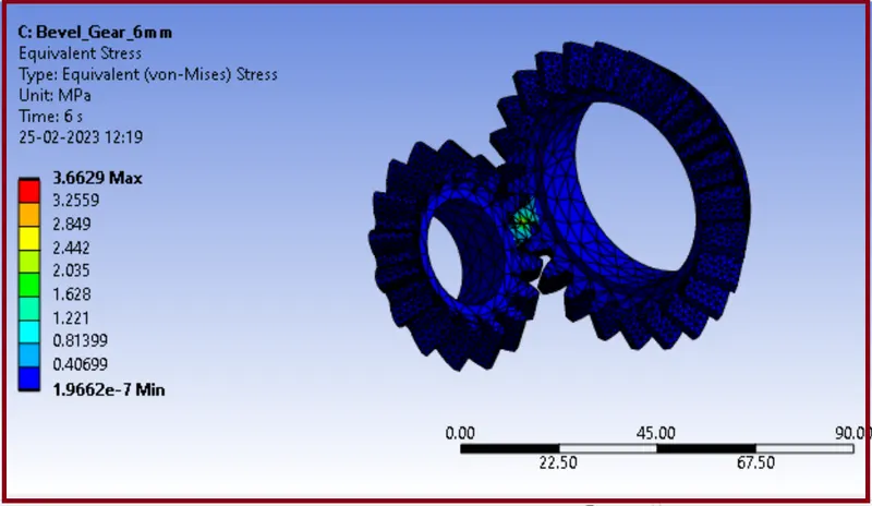
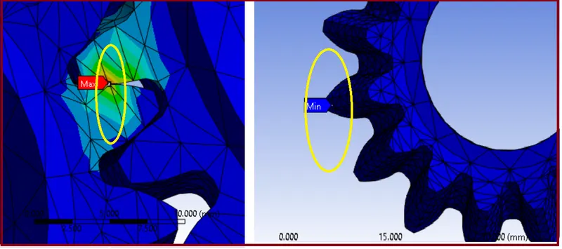
CASE: 1 Global Mesh size is 6 mm Face sizing is 1.75 mm.
- Stress
Animation....
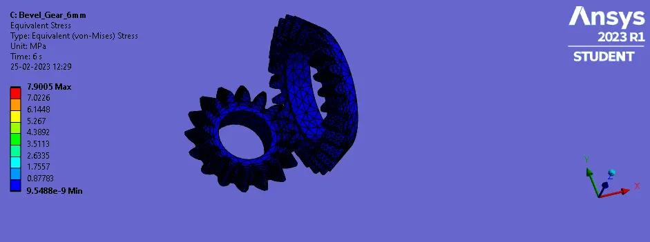
- Stress vs time Graph
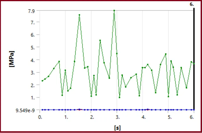
- Detailed Stress Result
|
Time (s) |
Minimum [MPa] |
Maximum [MPa] |
Average [MPa] |
|
0.1 |
9.5488e-009 |
2.3245 |
1.1495e-002 |
|
0.55 |
1.3165e-007 |
3.2918 |
1.2301e-002 |
|
1. |
2.5798e-007 |
3.1556 |
1.396e-002 |
|
1.55 |
1.9183e-007 |
7.5371 |
2.8483e-002 |
|
2. |
9.3491e-008 |
1.0674 |
8.5526e-003 |
|
2.5 |
8.158e-008 |
3.746 |
1.2343e-002 |
|
3. |
1.7483e-007 |
4.478 |
1.4838e-002 |
|
3.55 |
6.6802e-008 |
2.5497 |
1.2314e-002 |
|
4. |
1.3228e-007 |
3.3444 |
1.272e-002 |
|
4.5 |
1.5295e-007 |
1.3774 |
9.7817e-003 |
|
5. |
2.0384e-007 |
1.065 |
7.8709e-003 |
|
5.5 |
2.3818e-007 |
3.3626 |
1.4126e-002 |
|
6. |
1.9662e-007 |
3.6629 |
1.2464e-002 |
- Elastic Strain
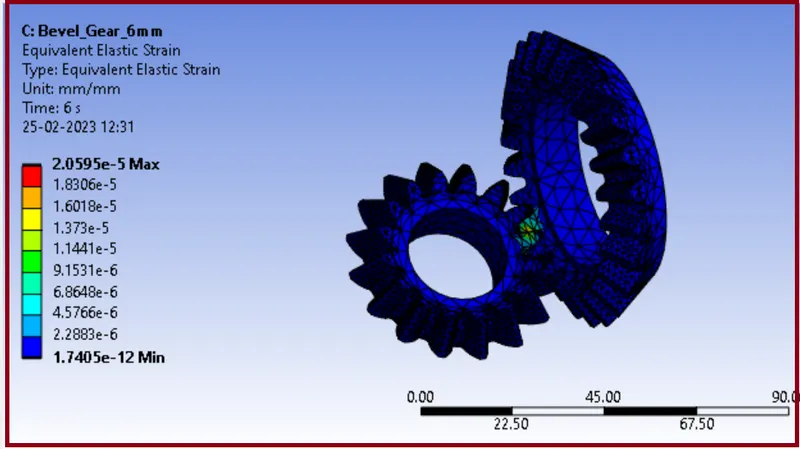
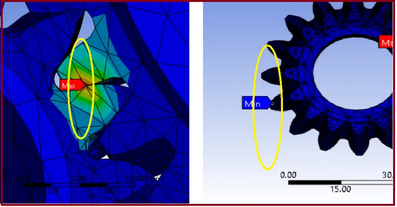
Animation....
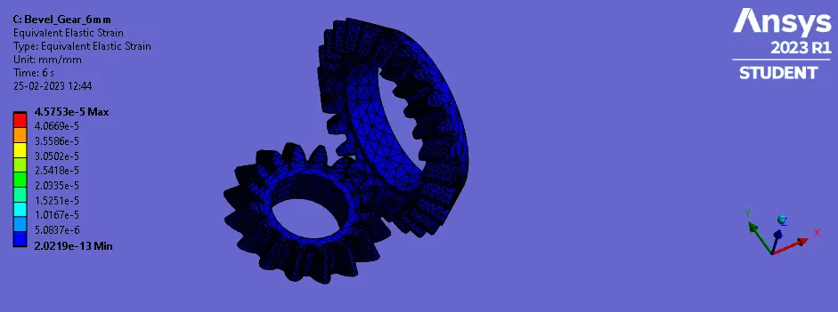
- Strain with time:
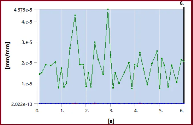
- Detailed Strain Result:
|
Time (s) |
Minimum [mm/mm] |
Maximum [ mm/mm] |
[mm/mm] |
|
0.1 |
2.0219e-013 |
1.4212e-005 |
6.9309e-008 |
|
0.55 |
1.4494e-012 |
1.839e-005 |
7.4643e-008 |
|
1. |
2.1311e-012 |
1.7256e-005 |
8.3742e-008 |
|
1.55 |
1.8428e-012 |
4.2906e-005 |
1.8175e-007 |
|
2. |
2.0898e-012 |
8.1941e-006 |
5.1727e-008 |
|
2.5 |
1.1504e-012 |
2.1505e-005 |
7.6023e-008 |
|
3. |
1.3181e-012 |
2.3587e-005 |
8.8867e-008 |
|
3.55 |
1.0188e-012 |
1.4943e-005 |
7.3994e-008 |
|
4. |
1.069e-012 |
1.8836e-005 |
7.6667e-008 |
|
4.5 |
1.3258e-012 |
9.0978e-006 |
5.9074e-008 |
|
5. |
1.7164e-012 |
7.2469e-006 |
4.8061e-008 |
|
5.5 |
2.0331e-012 |
1.8643e-005 |
8.4379e-008 |
|
6. |
1.7405e-012 |
2.0595e-005 |
7.6715e-008 |
- Total Deformation
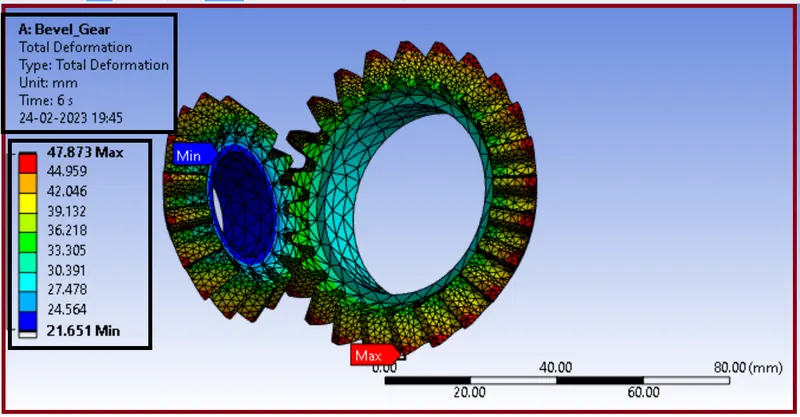
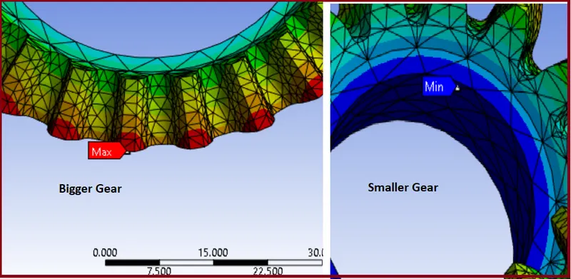
Animation....
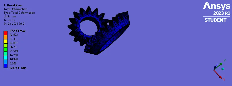
- Deformation graph with time:
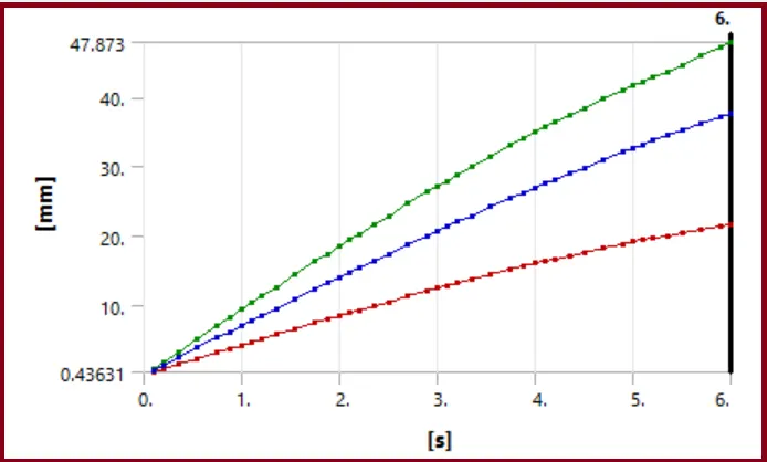
- Detailed Deformation Result:
|
Time (s) |
Minimum (mm) |
Maximum (mm) |
Average (mm) |
|
0.1 |
0.43631 |
0.94711 |
0.71779 |
|
0.55 |
2.3961 |
5.2014 |
3.9177 |
|
1. |
4.3412 |
9.4236 |
7.1142 |
|
1.55 |
6.681 |
14.503 |
10.945 |
|
2. |
8.5505 |
18.561 |
14.073 |
|
2.5 |
10.565 |
22.935 |
17.416 |
|
3. |
12.5 |
27.134 |
20.72 |
|
3.55 |
14.518 |
31.514 |
24.195 |
|
4. |
16.07 |
34.883 |
26.947 |
|
4.5 |
17.678 |
38.373 |
29.872 |
|
5. |
19.151 |
41.572 |
32.633 |
|
5.5 |
20.479 |
44.509 |
35.248 |
|
6. |
21.651 |
47.873 |
37.656 |
CASE: 2 Global Mesh size is 5 mm Face sizing is 1.75 mm.
- Stress
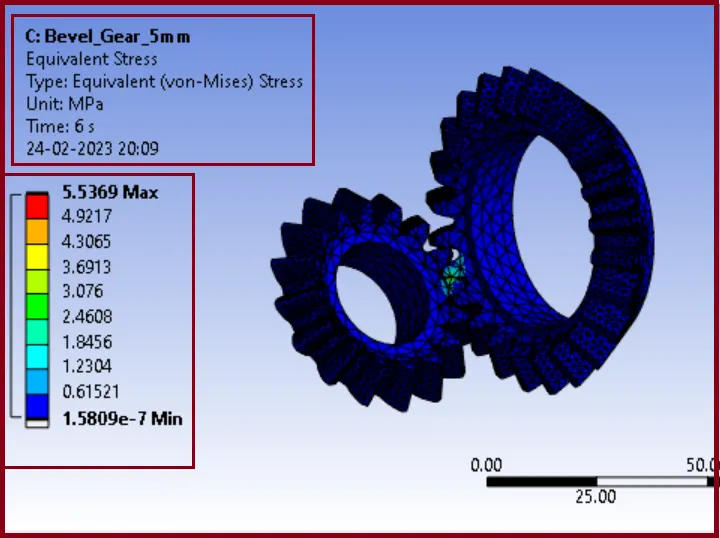
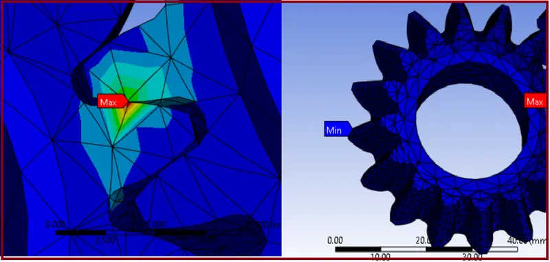
Animation....
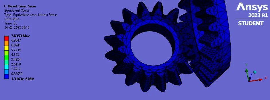
- Stress vs time Graph
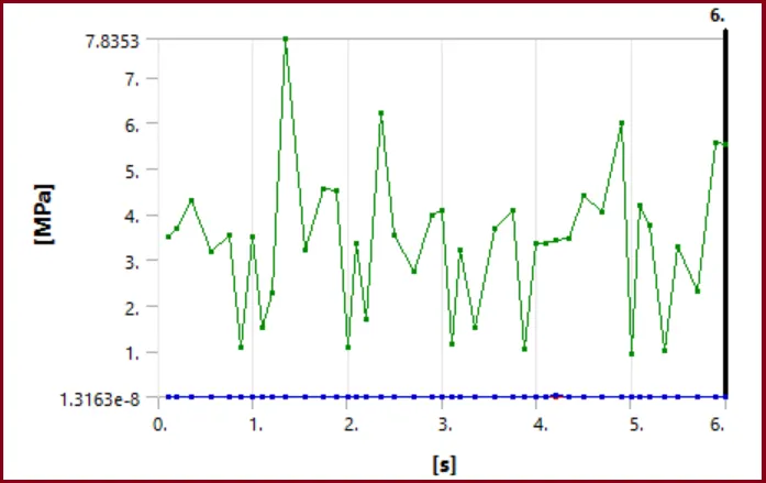
- Detailed Stress Result:
|
Time (s) |
Minimum [MPa] |
Maximum [MPa] |
Average [MPa] |
|
0.1 |
1.9138e-008 |
3.5025 |
1.202e-002 |
|
0.55 |
1.7338e-007 |
3.1892 |
1.2657e-002 |
|
1. |
1.9648e-007 |
3.4889 |
1.4132e-002 |
|
1.1 |
8.1488e-008 |
1.4994 |
1.0201e-002 |
|
1.55 |
1.513e-007 |
3.212 |
1.148e-002 |
|
2. |
7.1391e-008 |
1.0724 |
8.5478e-003 |
|
2.5 |
9.9049e-008 |
3.5372 |
1.2558e-002 |
|
3. |
8.5391e-006 |
4.0959 |
1.4618e-002 |
|
3.55 |
1.4645e-007 |
3.6822 |
1.2376e-002 |
|
4. |
1.2181e-007 |
3.3725 |
1.2704e-002 |
|
4.5 |
1.2992e-007 |
4.4032 |
1.2009e-002 |
|
5. |
2.0729e-007 |
0.9405 |
8.0327e-003 |
|
5.5 |
1.9322e-007 |
3.2815 |
1.3842e-002 |
|
6. |
1.5809e-007 |
5.5369 |
1.2621e-002 |
- Elastic Strain
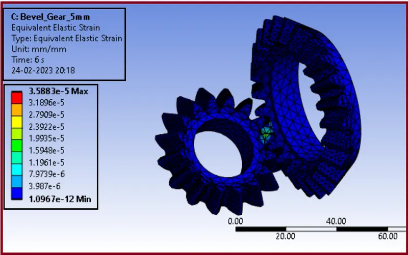
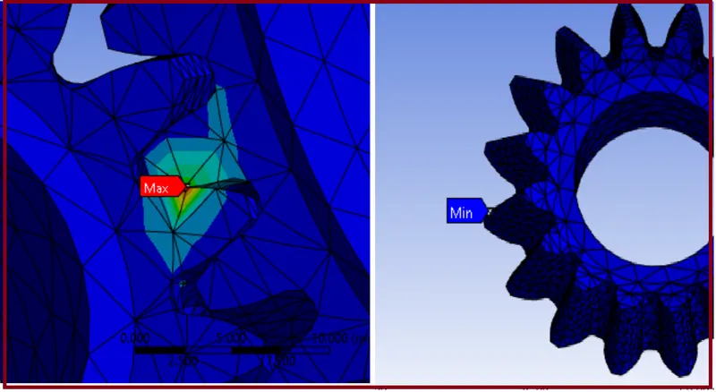
Animation....
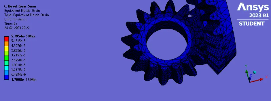
- Strain with time Graph:
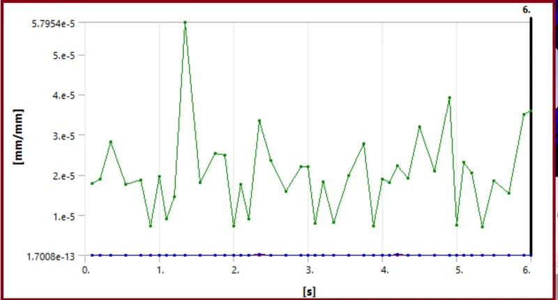
- Detailed Strain Result:
|
Time (s) |
Minimum (mm/mm) |
Maximum (mm/mm) |
Average (mm/mm) |
|
0.1 |
1.8072e-013 |
1.7954e-005 |
7.1763e-008 |
|
0.55 |
1.3458e-012 |
1.7584e-005 |
7.6116e-008 |
|
1. |
1.4205e-012 |
1.9537e-005 |
8.4658e-008 |
|
1.55 |
1.2195e-012 |
1.8034e-005 |
6.9086e-008 |
|
2. |
1.9795e-012 |
7.2644e-006 |
5.1184e-008 |
|
2.5 |
9.5972e-013 |
2.3593e-005 |
7.6087e-008 |
|
3. |
7.589e-011 |
2.2076e-005 |
8.7085e-008 |
|
3.55 |
1.2346e-012 |
1.9915e-005 |
7.4081e-008 |
|
4. |
1.304e-012 |
1.901e-005 |
7.6617e-008 |
|
4.5 |
1.1341e-012 |
3.1991e-005 |
8.3748e-008 |
|
5. |
1.5479e-012 |
7.3947e-006 |
4.8992e-008 |
|
5.5 |
1.2517e-012 |
1.8403e-005 |
8.2739e-008 |
|
6. |
1.0967e-012 |
3.5883e-005 |
7.7264e-008 |
- Total Deformation
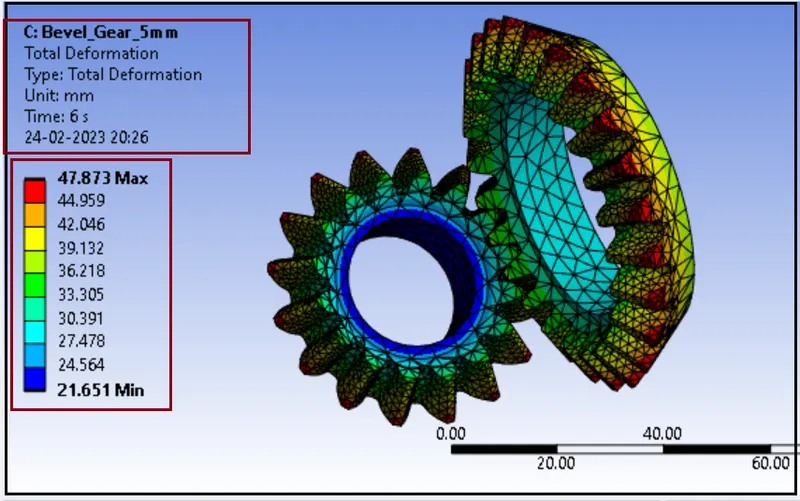
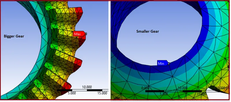
Animation....
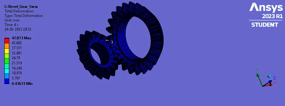
- Deformation graph with time:
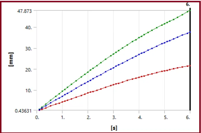
- Detailed Deformation Result:
|
Time (s) |
Minimum (mm) |
Maximum (mm) |
Average (mm) |
|
0.1 |
0.43631 |
0.94711 |
0.71501 |
|
0.55 |
2.3961 |
5.2014 |
3.9025 |
|
1. |
4.3412 |
9.4236 |
7.0867 |
|
1.55 |
6.681 |
14.503 |
10.902 |
|
2. |
8.5505 |
18.561 |
14.018 |
|
2.5 |
10.565 |
22.935 |
17.349 |
|
3. |
12.5 |
27.134 |
20.639 |
|
3.55 |
14.518 |
31.514 |
24.1 |
|
4. |
16.07 |
34.883 |
26.841 |
|
4.5 |
17.678 |
38.373 |
29.754 |
|
5. |
19.151 |
41.572 |
32.503 |
|
5.5 |
20.479 |
44.509 |
35.107 |
|
6. |
21.651 |
47.873 |
37.505 |
CASE: 3 Global Mesh size is 4 mm Face sizing is 1.75 mm.
- Stress
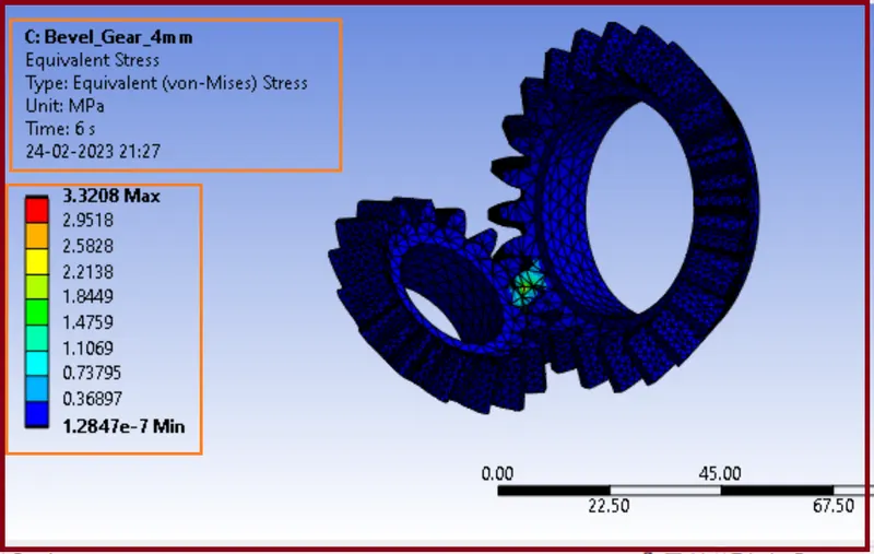
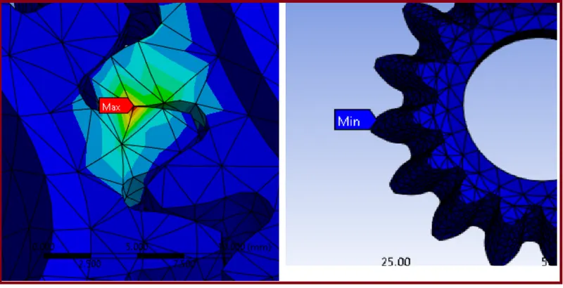
Animation....
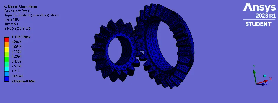
- Stress vs time Graph
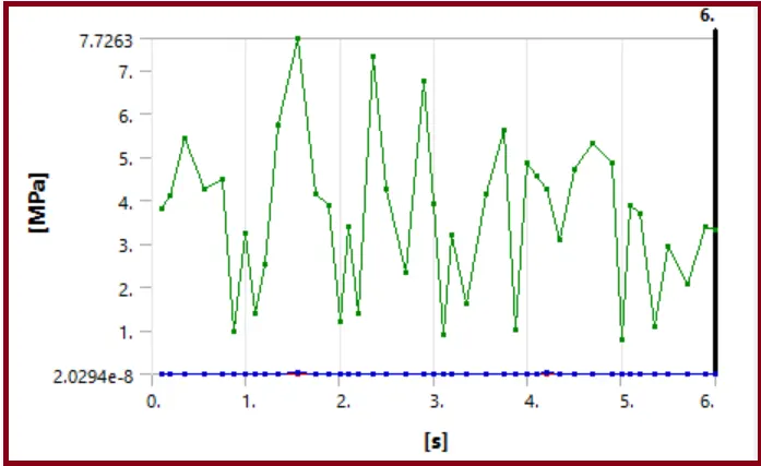
- Detailed Stress Result:
|
Time (s) |
Minimum [MPa] |
Maximum [MPa] |
Average [MPa] |
|
0.1 |
2.0294e-008 |
3.821 |
1.1701e-002 |
|
0.55 |
1.8364e-007 |
4.2661 |
1.2454e-002 |
|
1. |
1.6703e-007 |
3.2583 |
1.4068e-002 |
|
1.55 |
1.5955e-007 |
7.7263 |
2.8043e-002 |
|
2. |
9.6887e-008 |
1.211 |
8.5753e-003 |
|
2.5 |
1.1061e-007 |
4.2573 |
1.2318e-002 |
|
3. |
8.9651e-006 |
3.9336 |
1.4395e-002 |
|
3.55 |
8.9146e-008 |
4.1547 |
1.231e-002 |
|
4. |
9.9564e-008 |
4.8665 |
1.2495e-002 |
|
4.5 |
1.054e-007 |
4.7122 |
1.1617e-002 |
|
5. |
1.8663e-007 |
0.78414 |
7.689e-003 |
|
5.5 |
1.7414e-007 |
2.9344 |
1.3208e-002 |
|
6. |
1.2847e-007 |
3.3208 |
1.1718e-002 |
- Elastic Strain
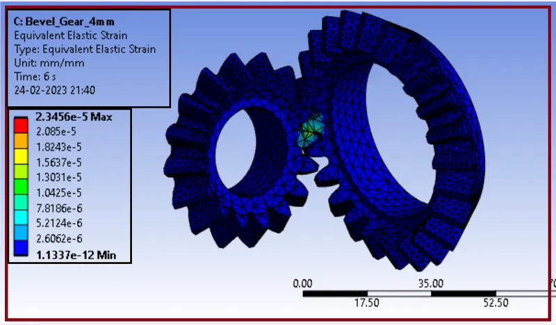
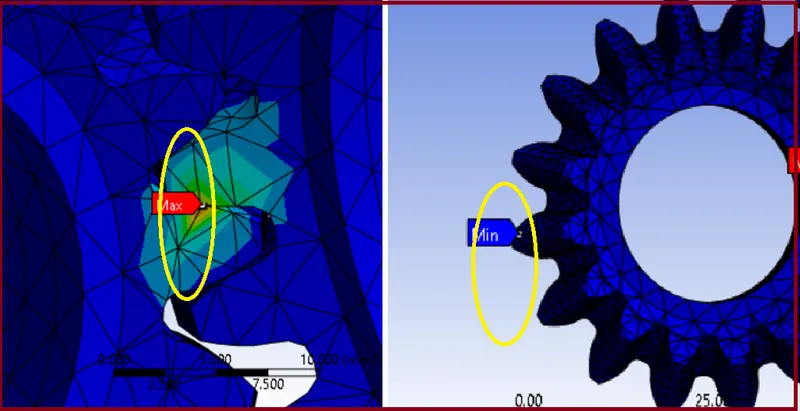
Animation....
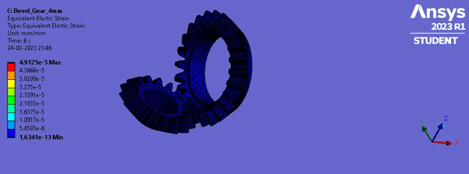
- Strain with time Graph:
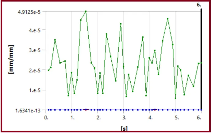
- Detailed Strain Result:
|
Time (s) |
Minimum (mm/mm) |
Maximum (mm/mm) |
Average (mm/mm) |
|
0.1 |
2.5943e-013 |
1.9672e-005 |
6.9552e-008 |
|
0.55 |
1.3816e-012 |
2.34e-005 |
7.4528e-008 |
|
1. |
1.3626e-012 |
1.8598e-005 |
8.3822e-008 |
|
1.55 |
1.1599e-012 |
4.9125e-005 |
1.7231e-007 |
|
2. |
1.9218e-012 |
8.1592e-006 |
5.1384e-008 |
|
2.5 |
1.1478e-012 |
2.6523e-005 |
7.4405e-008 |
|
3. |
8.5559e-011 |
2.1584e-005 |
8.592e-008 |
|
3.55 |
1.0427e-012 |
2.1441e-005 |
7.3061e-008 |
|
4. |
1.0163e-012 |
2.6008e-005 |
7.471e-008 |
|
4.5 |
1.0277e-012 |
3.4361e-005 |
7.9647e-008 |
|
5. |
1.4345e-012 |
5.8311e-006 |
4.6322e-008 |
|
5.5 |
1.3325e-012 |
1.722e-005 |
7.8687e-008 |
|
6. |
1.1337e-012 |
2.3456e-005 |
7.1269e-008 |
- Total Deformation
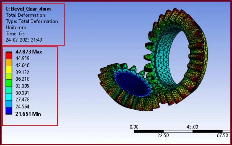
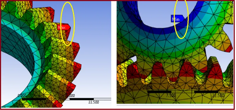
Animation....
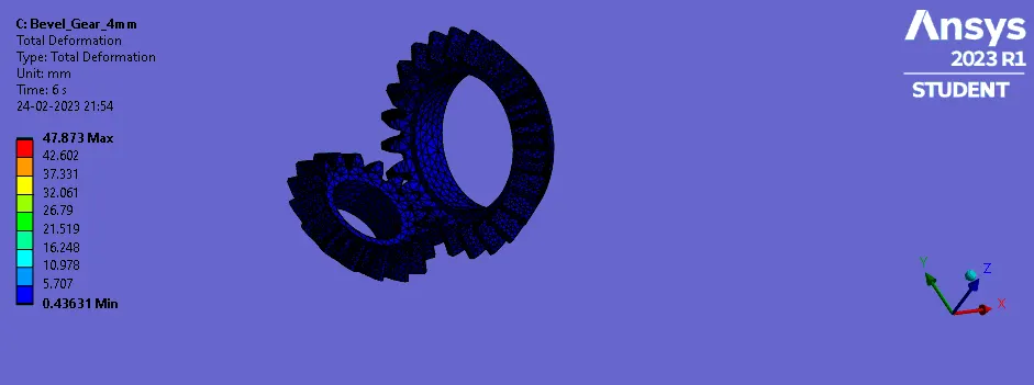
- Deformation graph with time:
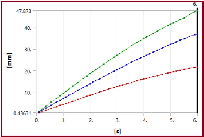
- Detailed Deformation Result:
|
Time (s) |
Minimum (mm) |
Maximum (mm) |
Average (mm) |
|
0.1 |
0.43631 |
0.94711 |
0.70799 |
|
0.55 |
2.3961 |
5.2014 |
3.8641 |
|
1. |
4.3412 |
9.4236 |
7.017 |
|
1.55 |
6.681 |
14.503 |
10.795 |
|
2. |
8.5505 |
18.561 |
13.881 |
|
2.5 |
10.565 |
22.935 |
17.179 |
|
3. |
12.5 |
27.134 |
20.437 |
|
3.55 |
14.518 |
31.514 |
23.865 |
|
4. |
16.07 |
34.883 |
26.58 |
|
4.5 |
17.678 |
38.373 |
29.465 |
|
5. |
19.151 |
41.572 |
32.189 |
|
5.5 |
20.479 |
44.509 |
34.769 |
|
6. |
21.651 |
47.873 |
37.145 |
COMPARISON:
|
CASES |
Maximum Stress [MPa] |
Minimum stress [MPa] |
Maximum Strain [mm/mm] |
Minimum strain [mm/mm] |
Maximum Deformation [mm] |
Minimum Deformation [mm] |
|
CASE:1 6mm |
3.6629 |
1.9662e-7 |
2.0595e-5 |
1.740e-12 |
47.873 |
21.651 |
|
CASE:2 5mm |
5.5369 |
1.5809e-7 |
3.5883e-5 |
1.0967e-12 |
47.873 |
21.651 |
|
CASE:3 4mm |
3.3208 |
1.2847e-7 |
2.3456e-5 |
1.1337e-12 |
47.873 |
21.651 |
- From above table, we can observe that CASE 1 and CASE 3 are nearly similar and CASE 2 values are Higher in comparison.
- We can also observe that maximum deformation occurs on Big Gear due to moment.
|
CASES |
No. of node |
No. of Element |
|
CASE: 1 6mm |
26415 |
14247 |
|
CASE: 2 5mm |
26493 |
14213 |
|
CASE:3 4mm |
28167 |
15152 |
CONCLUSION:
we can conclude after performing grid dependency test on bevel gear by varying the global size of the mesh we achieve much better accuracy of the result. We can observe that as the mesh is refined from 6mm to 5mm and 5mm to 4mm we achieve better approximate of the result for equivalent elastic strain and equivalent stress, however, performing the simulation with further refining the mesh would result in a very close approximation of the result but with very negligible change in the result with an additional on the computational power and time.
**********************************************************************************************************************************************************************************************************************************************************************END
Here Due to large size of the Ansys file, i have attached a link for the Ansys .wbpz file in below "Model Browse" area.
Kindly find attached link via word document.
Thanks & regards,
Devesh kashyap