Week 2 Railwheel and Track
AIM: To Perform static structural analysis/simulation on the Rail wheel and track.
OBJECTIVE:
To evaluate the result for stress, strain, and total deformation and the product life cycle.
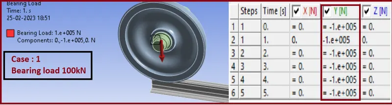
- CASE:1 Bearing load is 100000 N.
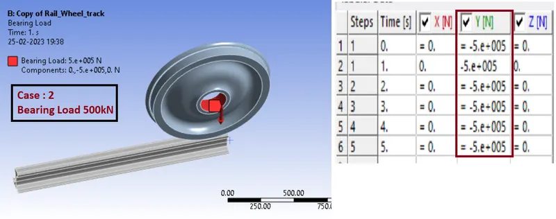
- CASE:2 Bearing load is 5times of 100000 N
-
Implement user-defined results and compare both the results.
THEORY: -
Rail wheels and tracks are two essential components of railway systems. The rail wheel is the wheel of the train, while the track is the rails that the train runs on.Rail wheels are typically made of steel and are designed to provide support, stability, and traction to the train. They are generally flanged, meaning that they have a rim that keeps them on the track and prevents them from derailing. The wheels are attached to the axles of the train, which rotate as the train moves.
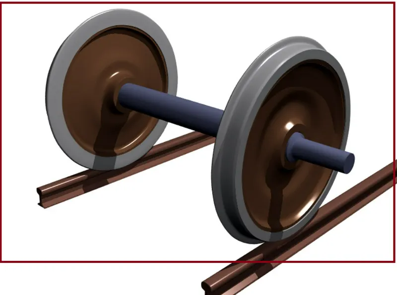
Tracks, on the other hand, are typically made of steel rails that are laid on a bed of ballast, which is usually composed of crushed stone or gravel. The rails are fastened to sleepers or ties, which are usually made of wood, concrete, or steel. The rails are typically laid in pairs, with a gap between them called the "gauge" that allows the wheels to pass through.Together, rail wheels and tracks work together to provide a smooth, stable surface for trains to travel on. The wheels provide the necessary traction, while the tracks provide a stable foundation and guide the train in the desired direction. Maintaining both the wheels and tracks is crucial for the safe and efficient operation of railway systems.
Fatigue Life:
- fatigue life refers to the number of cycles or the amount of time a material or structure can withstand cyclic loading before failure occurs. Fatigue failure is a common mode of failure in structures subjected to repeated loading and unloading, such as bridges, aircraft structures, and machinery components.
- The fatigue life of a material or structure is influenced by a variety of factors, including the stress range, the mean stress level, the number of cycles, the material properties, and the geometry of the structure. Therefore, fatigue life is usually predicted using empirical fatigue life models that take into account these factors.
- In ANSYS Mechanical, fatigue life can be predicted using the Fatigue Tool, which is a module that is available in ANSYS Mechanical for fatigue life analysis. The Fatigue Tool can be used to predict the number of cycles required to cause fatigue failure for a given stress range and mean stress level, or to predict the stress range required to achieve a given fatigue life.
- To use the Fatigue Tool, you need to define the loading and boundary conditions, specify the material properties, and select the appropriate fatigue life model. ANSYS Mechanical provides a range of fatigue life models, including the Coffin-Manson, Morrow, Smith-Watson-Topper, and Fatemi-Socie models.
- After the analysis is run, the results can be displayed in the form of fatigue life curves, which show the relationship between the applied cyclic loading and the predicted fatigue life. These curves can be used to evaluate the fatigue life of the structure and to identify critical locations that may require design modifications to improve fatigue performance.
ANALYSIS:
Here we will perform an analysis on Rail wheel track. We will use different bearing load and find out the Equivalent stress, Total Deformation and working life of
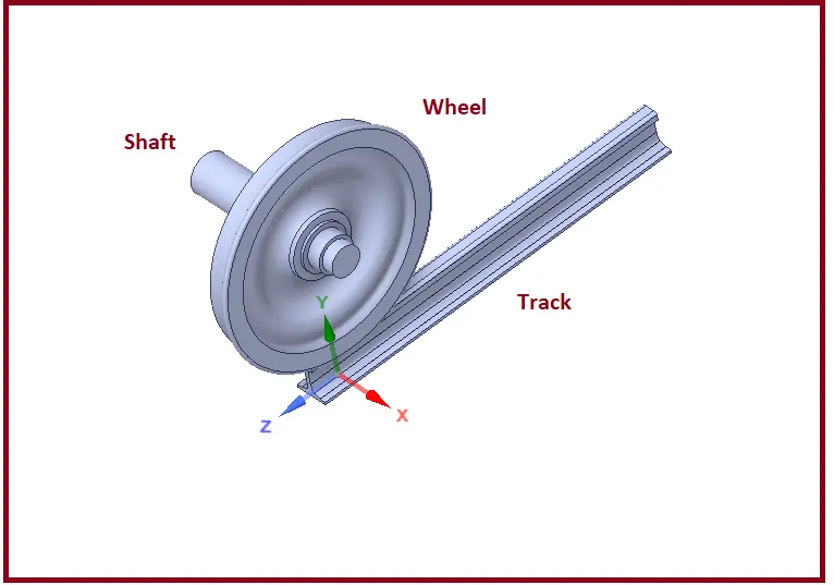
- Given Geometry:
Rail wheels & tracks geometry for analysis of all cases is given as below
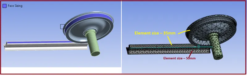
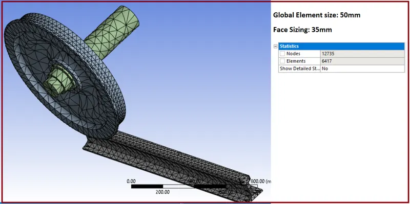
- Mesh:
- Material :
By default material is “Structural Steel”.
- Connections:
Make contacts based on definitions.
Contact: 1st one
- Contact Body = Wheel
- Target Body = Running Rail
- Type: Frictional
- Friction Coefficient: 0.3
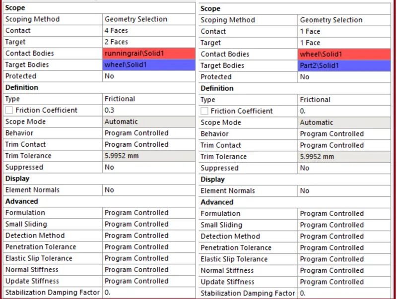
Contact: 2nd one
- Contact Body = Shaft
- Target Body = Wheel
- Type: Frictionless
- Joints:
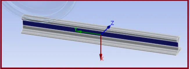
Joint: 1st
- Connection Type: Body-Ground
- Type: Fixed
- Body: Running Rail
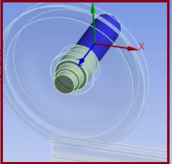
Joint: 2nd
- Connection Type: Body-Ground
- Type: Translational
- Body: Shaft
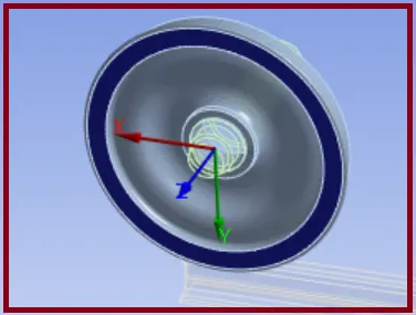
Joint: 3rd
- Connection Type: Body-Ground
- Type: Planar
- Body: Wheel
- Boundary Conditions settings:
After meshing and after defining the joints as described above, our next step is creating Boundary Conditions:
Analysis Settings:
- No. of Steps = 5
- Solver Type: Direct
- Output Controls: All Yes
- Non-Linear Controls: Force Convergence: ON
Now Time Step Controls:
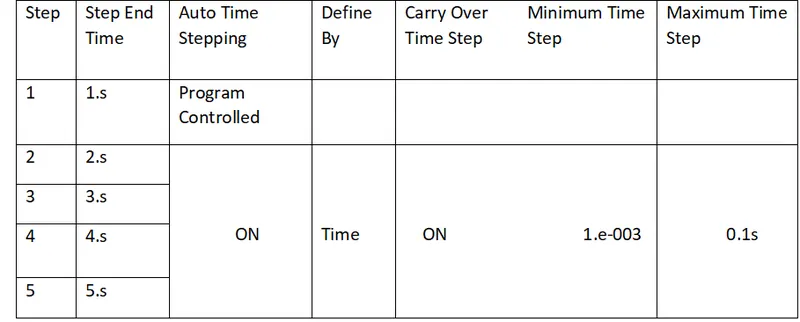
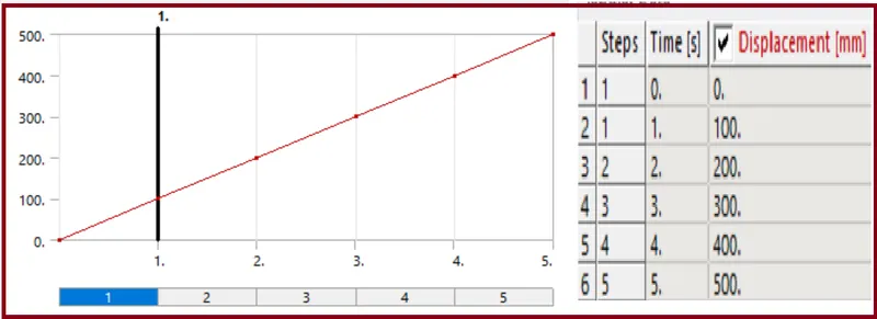
Here we want Translation motion of Wheel on the track, the Running distance 500 mm with 100 mm on each step.
Also, there we involve a bearing load imposed by a carriage transferred to shaft and from shaft to Wheel through Hole.
- Bearing Load:
- Joint Displacement:
- Joint: Translational – Ground to Shaft
- Type: Displacement
- Magnitude: Tabular Data
- Tabular Data is…
SOLUTION
After giving proper boundary conditions, create desired solutions for output results. Create Solutions for Equivalent (Von Mises) Stress, Total Deformation and create solution for Fatigue Life.
Now we observe results with comparison.
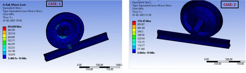
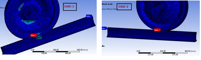
Results for CASE: 1 {100kN} and CASE: 2 {500kN} are as given below:
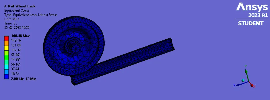
- Stress
- Stress Plots:
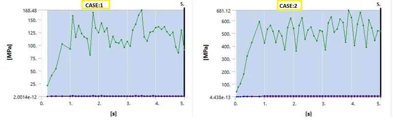
- Detailed Stress Data:
CASE: 1 CASE:2

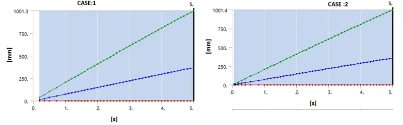
- Deformation
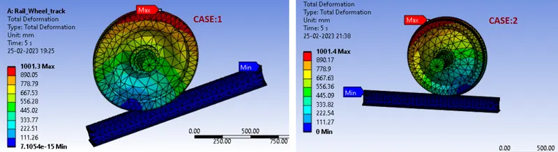
- Deformation Plots:
- Detailed Deformation Result:
CASE: 1 CASE:2

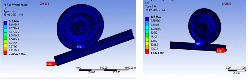
- Fatigue Life:
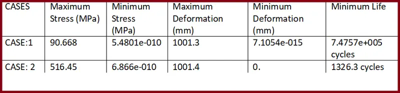
- Maximum and Minimum result COMPARISON:
Animation …..
Stress CASE:1
Deformation CASE: 1
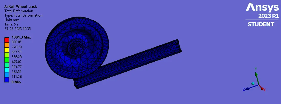
Stress CASE:2
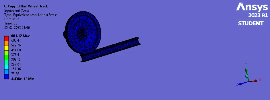
Deformation CASE: 2
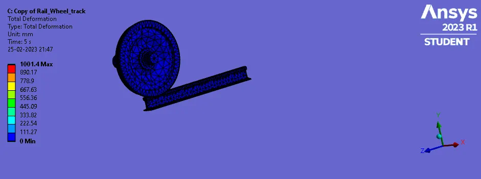
User Defined Result:
In industry, we can observe customers ask for ways to output custom results from Ansys Mechanical. The usual results like Total Deformation, Equivalent Stress or Equivalent Plastic Strain may not be enough for our needs. Depending on the requirements, we can create User Defined Results to output the needed result.
- In ANSYS Mechanical, users can define their own results using the APDL (ANSYS Parametric Design Language) commands. APDL commands can be used to define custom result items based on the existing results or to calculate new results based on the solution data.
- There are various output quantities given in the Worksheet of Ansys Mechanical.
- Somehow, any results not output automatically, then we can write expression for that result and get needed results.
- If we want Total Deformation results, then we can use algebraic equation for Resultant Deformation in the form of vector quantities.
- Here we want to find out the Total Deformation as a User Defined Result and want to check if it is similar to inbuilt result.
So, symbol for the Deformation used is U.
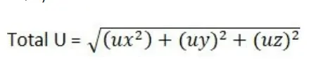
We can write also,

User defined results for both cases are as given below:
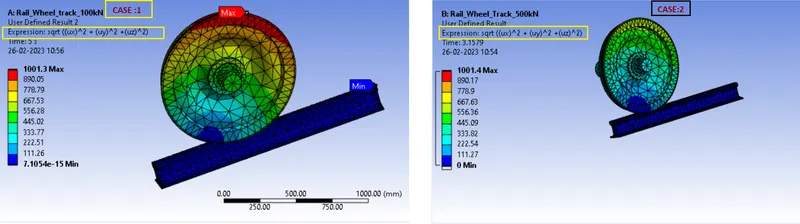
We can observe this result (User defined result) for deformation is same as total deformation.
CONCLUSION:
- Here we can observe comparative results, we can see high amount of increase in Stress.
- Total deformation is same for both the cases. (in CASE:2 because of the error, we redefine the contacts so variation is there in result)
- User Defined results are same as inbuilt results and near same in both cases.
- We know that Tensile Yield Strength of Structural Steel is 250 MPa. So, in case of 500 kN loads, Stress is going beyond the limit up to 516.45 MPa. So, there will be plastic deformation or permanent deformation can happen.
- As per results, we can see that fatigue life in 100kN loads is minimum 7.4757e+5 (7.4757 x 10^5) cycles and for 500kN loads it is only 1326 cycles.
So, we should avoid higher loads for safety purpose
**************************************************************************************************************************************************************************************************************************************************************************END
Here Due to large size of the Ansys file, i have attached a link for the Ansys .wbpz file in below "Model Browse" area.
Kindly find attached link via word document.
Thanks & regards,
Devesh kashyap