Project
AIM:- To do a detailed analysis on CVT ( continuous variable Transmission) using BAJA ATV vehicle and present the observation.
Theory:-
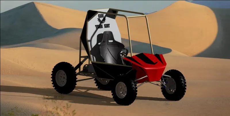
BAJA ATV (SAE):-
- Baja SAE is an Collegiate Design Series competition run by the Society of Automotive Engineers International (SAE International). Teams of students from universities all over the world design and build small off-road cars. The cars all have engines of the same specifications. As of 2018 the engine has been an unmodified Briggs & Stratton Model 19 Vanguard engine single-cylinder with a displacement of 305cc and power output of approximately 10 bhp (7.5 kW).
-
The goal in Baja SAE racing is to design, build and race off-road vehicles that can withstand the harshest elements of rough terrain. The vehicles used in Baja SAE racing are often similar in appearance to dune buggies. Before 2007, the events were called "Mini Baja."
- Each year as many as 141 Baja cars are entered in the Baja SAE events across the US and around the world. International events are endorsed by SAE International and are held in Brazil, Korea, South Africa and Mexico.
-
The Baja SAE Competition originated at the University of South Carolina in 1976, under the supervision of Dr. Harit Mehta. Only 10 teams took part in the very first race. Since that time, the competition has grown to become a premier engineering design series with over 110 university teams participating in each race.
-
The BAJA SAE tasks the students to design, fabricates and validate a signal seater four – wheeled off road vehicle to take part in series of events spread over a course of 3 days that test the vehicle for the sound engineering practices that have gone into it, the agility of the vehicle in terms of grade ability ,speed, acceleration and maneuverability characteristics and finally its ability to endure that brake breaking durability test.
All Terrain Vehicle:-
- An all-terrain vehicle (ATV), also known as a light utility vehicle (LUV), a quad bike, or simply a quad, as defined by the American National Standards Institute (ANSI); is a vehicle that travels on low-pressure tires, with a seat that is straddled by the operator, along with handlebars for steering control. As the name implies, it is designed to handle a wider variety of terrain than most other vehicles.
- These vehicles like a motorcycle, but the extra wheels give more stability at slower speeds. Although most are equipped with three or four wheels, six-wheel models exist and existed historically for specialized applications. Multiple-user analogues with side-by-side seating are called utility terrain v Engine sizes of ATVs currently for sale in the United States (as of 2008 products) range from 49 to 1,000 cc Vehicles (UTVs) or side-by-sides to distinguish the classes of vehicle.
- ATVs accounted for 58% of the SI (spark ignited) vehicles produced 0.16% of NOx, 8% of HC, 5% of CO and 0.8% of PM emissions for all vehicles, both highway and nonroad.
Continous variable Transmission (CVT):-
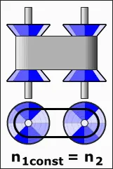
- A continuously variable transmission (CVT) is an automatic transmission that can change seamlessly through a continuous range of gear ratios. This contrasts with other transmissions that provide a limited number of gear ratios in fixed steps. The flexibility of a CVT with suitable control may allow the engine to operate at a constant RPM while the vehicle moves at varying speeds.
- CVTs are used in automobiles, tractors, motor scooters, snowmobiles, bicycles and earthmoving equipment.
- The most common type of CVT uses two pulleys connected by a belt or chain, however, several other designs have also been used at times.
Types of CVT:-
1.0 Pulley-based
2.0 Toroidal
3.0 Ratcheting
4.0 Hydrostatic/hydraulic
5.0 Electric
6.0 Cone
7.0 Epicyclic
BLOCKS USED:-
- Generic Engine:-
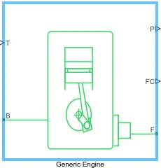
- Represents a system-level model of spark-ignition and diesel engines suitable for use at initial stages of modeling when only the basic parameters are available. Optional idle speed and red line controllers are included.
- The throttle input signal T lies between zero and one and specifies the torque demanded from the engine as a fraction of the maximum possible torque. If the engine speed falls below the Stall speed, the engine torque is blended to zero. If the engine speed exceeds the Maximum speed, the simulation stops and issues an error message.
- Connections F and B are mechanical rotational conserving ports associated with the engine crankshaft and engine block, respectively. Connections P and FC are physical signal output ports through which engine power and fuel consumption rate are reported.
2. Engine sensor:-
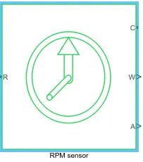
- Engine sensor is connected with Generic Engine. it contain mainly RPM sensor.
- This block measures angular velocity or angle in a mechanical rotational network. The sensor is ideal since it does not account for inertia, friction, delays, energy consumption, and so on.
- The physical signal ports W and A report the angular velocity and angle, respectively, of port R relative to port C. The measured angular velocity is positive when the angular velocity at port R is greater than the angular velocity at port C.
3. Simple Gear:-
Engine is connected with simple gear ratio for speed reduction
CVT ( Continous variable Transmission )
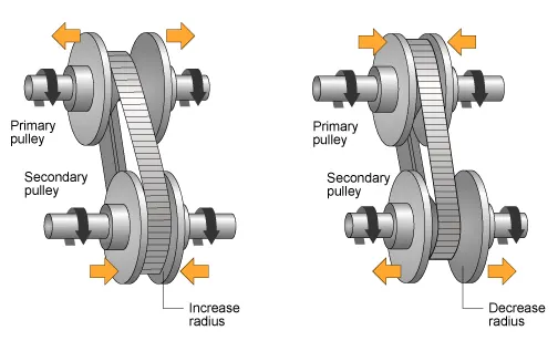
The main components of CVT:-
a.) Primary pulley
b.) Secondary pulley
c.) Belt
d.) Variator
The above figure shows the CVT variator with two configurations. In the first configuration, which illustrates speed reduction, the variator is set to decrease the primary pulley radius and increase the secondary pulley radius. In the second configuration, which illustrates overdrive, the variator is set to increase the primary pulley radius and decrease the secondary pulley radius.
CVT ratio ( Generate CVT ratio with the help of signal builder block ):-
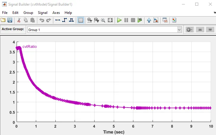
Here CVT Ratio Block is Connected with CVT by giving random ratio values to get the value of velocity for those random CVT value.
4. Vehicle Body:-
- The Vehicle Body block represents a two-axle vehicle body in longitudinal motion. The vehicle can have the same or a different number of wheels on each axle. For example, two wheels on the front axle and one wheel on the rear axle. The vehicle wheels are assumed identical in size. The vehicle can also have a center of gravity (CG) that is at or below the plane of travel.
- The block accounts for body mass, aerodynamic drag, road incline, and weight distribution between axles due to acceleration and road profile. Optionally include pitch and suspension dynamics. The vehicle does not move vertically relative to the ground.
- The block has an option to include an externally-defined mass and an externally-defined inertia. The mass, inertia, and center of gravity of the vehicle body can vary over the course of simulation in response to system changes.
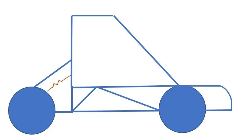
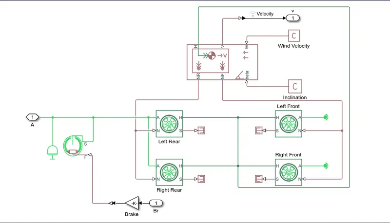
- Here vehicle Body contains Two Front wheel and Two rear wheel which is connected with inertia Output Shaft and Double shoe Brake.
5. Signal Builder:-
To provide input values for Throttle and Brake we require signal builder. we connect it with the Generic Engine Block.
Here Brake input = 0 [0-80] sec.
Throttle input=0.5 for [0-80]sec.
OTHER BLOCKS:-
- Solver configuration- To specify the solver parameters before starting the simulation.
- Mechanical Reference- To make sure all the components are clamped to the ground.
- Simulink to PS convertor- To convert simulink signal to simscape environment.
- PS to simulink convertor- To convert simscape signal to simulink environment.
- Rotational Motion Sensor-To sense the engine Rotation and give output in RPM.
- Variable Gear Ratio – To vary the speed according to the gear ratios.
- Double shoe Brake - a brake arranged as two pivoted rigid shoes symmetrically installed inside or outside a drum and operated by one actuator. The actuator force causes the shoes to exert a friction torque on a shaft connected to the drum.
- PS Terminator- terminates for unconnected physical signal.
- Tire- For translation motion of the vehicle
- Inertia- To represent solid (rigid) inertia
- PS constant-Generate constant physical signal
- Rotations free End- for mechanical component.
- Custom Measure Gauge- to measure the break and throttle input.
- Lookup Table-To inserts the CVT values from the workspace.
- Knob- To increase, decrease and vice-versa of throttle and brake inputs.
- Step- To increase and decrease an input value for a defined time interval
- Scope- To view the graph of the parameters for celerity
- Display- To view the calculated engine power.
ANALYSIS:1 (BAJA ATV WITH CVT)
Model:-
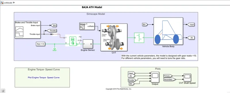
Analysis Results:-
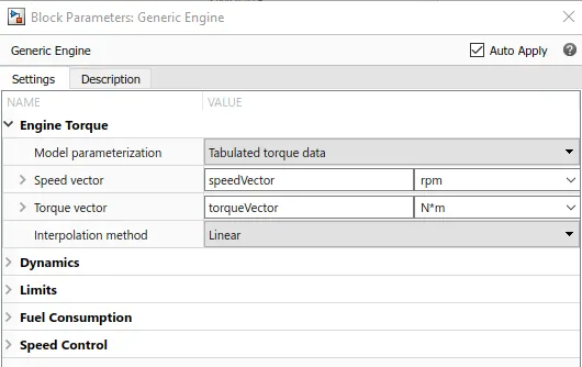
- Engine Torque vs speed curve
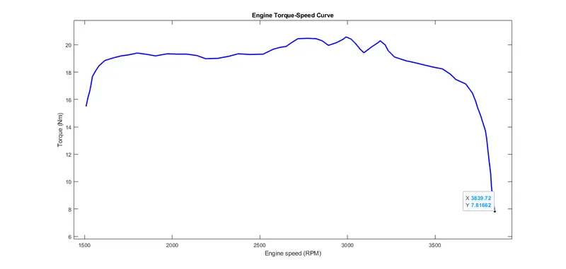
Here we see that the engine speed reaches to ~4000 RPM.
- OUTPUT RESULT:-
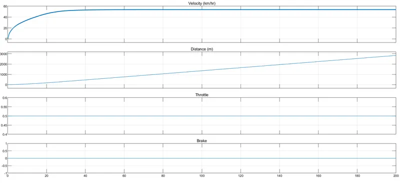
Here we can observe that the velocity increase over 40 sec, and after that it will constant. We also observe the distance cover is ~ 3km with 0.5 throttled input and no brake applied.
- CVT shaft speed:-
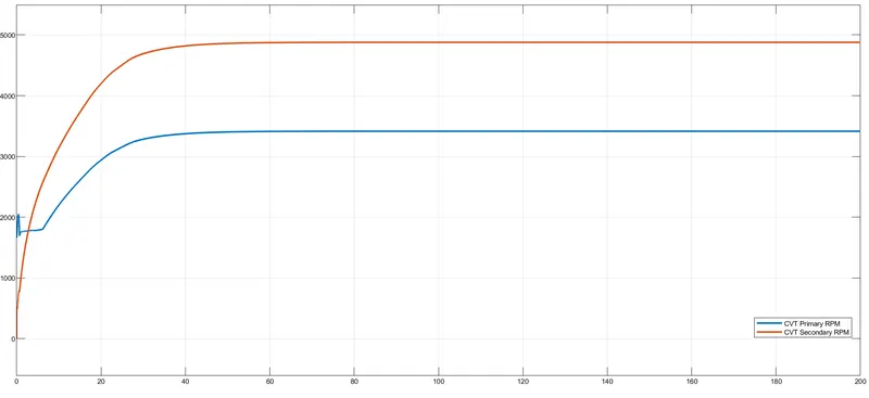
Here we observe that secondary pulley rpm is greater than primary pulley, because when we accelerate the vehicle the primary pulley will expand and secondary pulley will extract this process in general we can say that speed reduction.
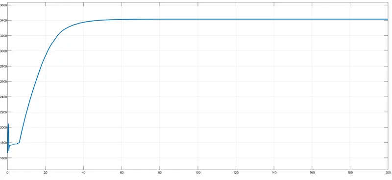
- Engine RPM:-
ANALYSIS:2 (BAJA CVT Model with Dashboard):-
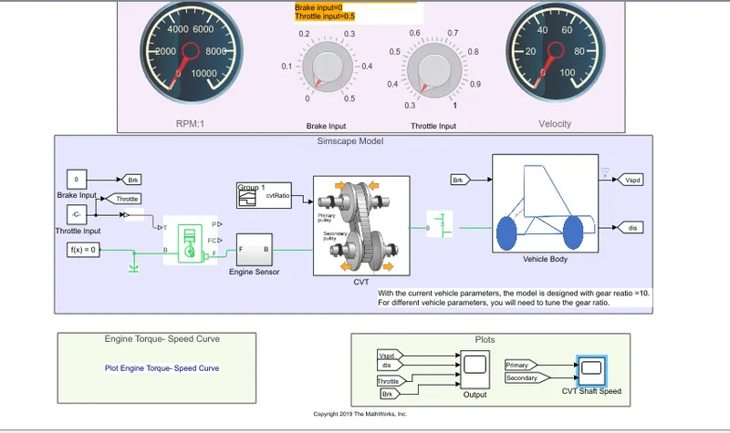
Here we used same Model with different input in running time for actual simulation. To give input dash board knobs are used which is connected with constant block which provide input in running time. Here we use infinite “inf” simulation time
- Circular gauge (Velocity,RPM)
- Circular knob ( Brake input, Throttle input)
Analysis Results:-
- OUTPUT RESULT:
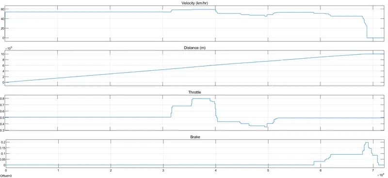
When we start the simulation the velocity is 60kmph and throttle knob is 0.5 and when we decrease the throttle the velocity is also decreasing .same thing happen when we apply brake
- CVT shaft speed:-
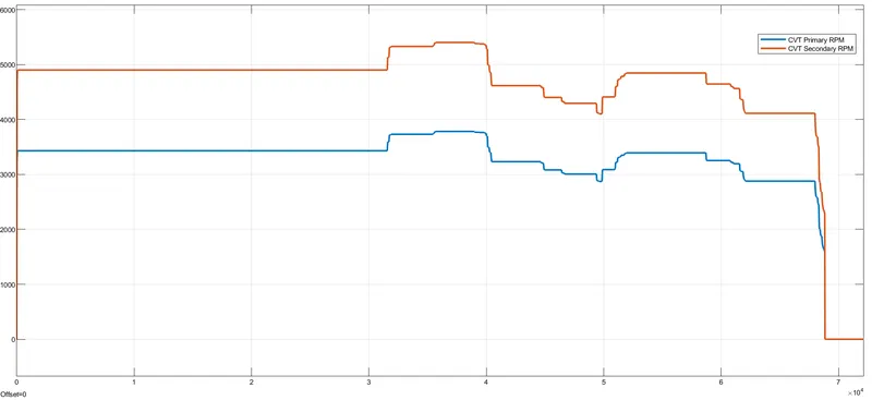
Here the velocity and CVT RPM are identical and primary pulley rpm is less than the secondary pulley rpm. Because we are using speed reduction Arrangement for CVT.
- Engine RPM:-
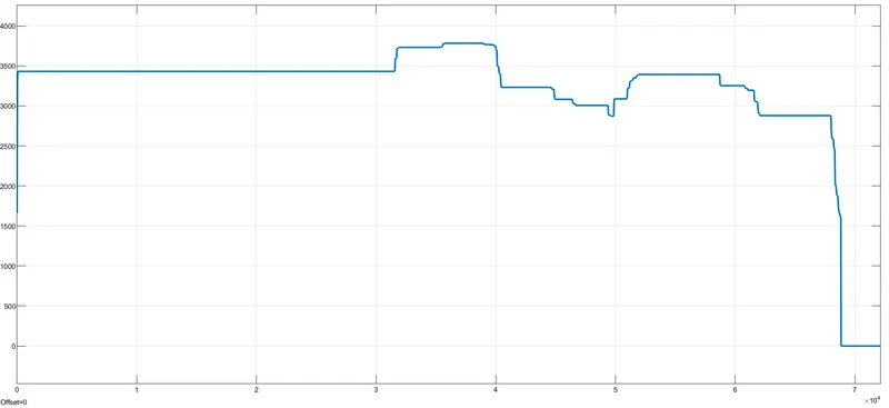
We observe when we increase the throttle value, Engine RPM is also increasing and when we increase the brake input engine RPM will go down.
ANALYSIS:3 (ATV WITH CVT using Look Up Table) or Mapped CVT Model
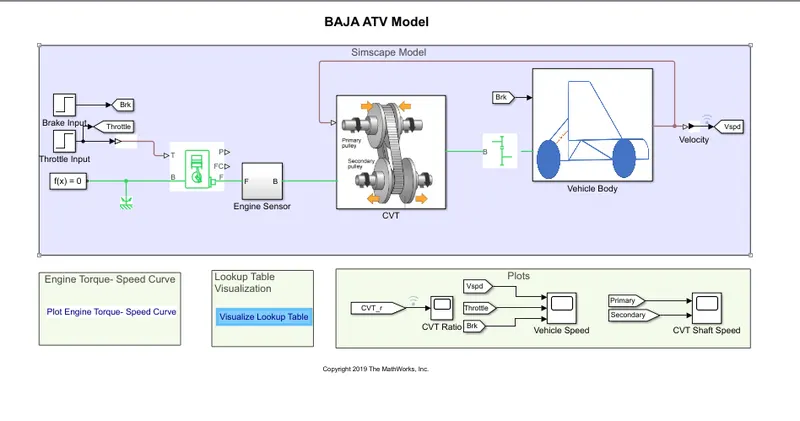
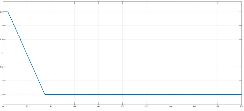
Here we use lookup table for input we extract data from workspace
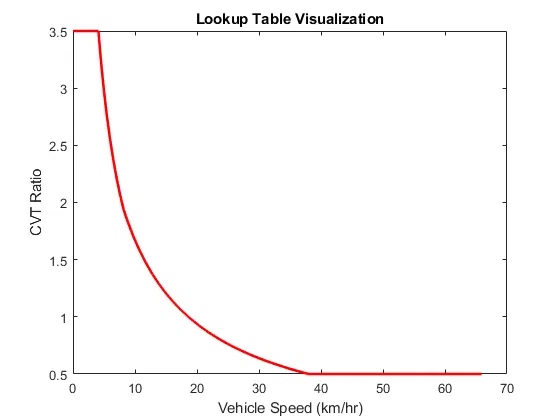
- Lookup table:- it is an array of data that maps input values to output values, thereby approximating a mathematical function. give a set of input values, a lookup operation retrieves the corresponding output values from the table.
- PS lookup table:-This block represents a physical signal converter whose input-output relationship is specified by a lookup table. The table grid must be in strictly ascending or strictly descending order, but the spacing can be nonuniform.
Right-click on the block and select Foundation Library > Plot Table to visualize the table data based on the selected interpolation and extrapolation methods.
Analysis Results:-
- Vehicle speed
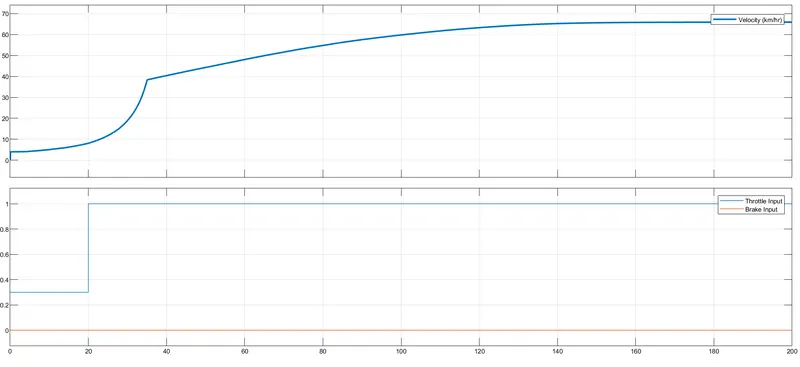
Here we can observe how the velocity changes with input (throttle and brake)
- CVT shaft speed
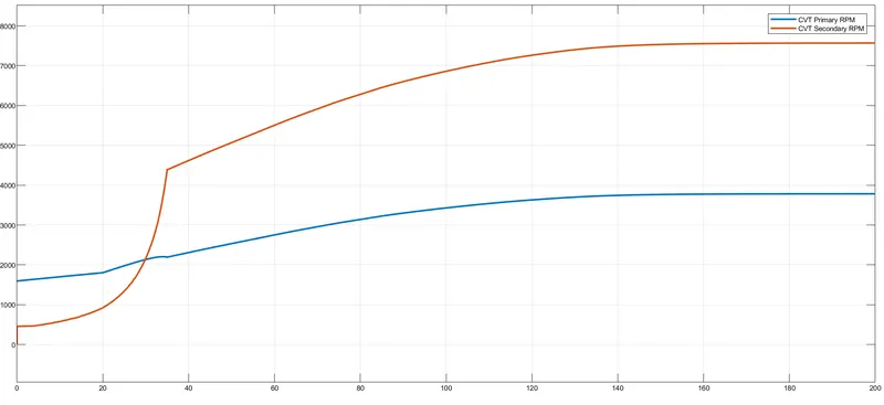
Here we can observe that till 35 sec the secondary pulley RPM is less than secondary pulley because of acceleration. After 35 sec again the secondary pulley RPM increased and primary pulley RPM decreased.
- Engine RPM
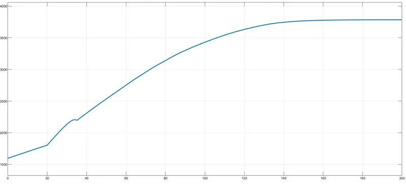
Here we observe same as previous after 35 sec engine RPM increased due to acceleration.
ANALYSIS:4 (ATV WITH CVT with DASHBOARD using Look Up Table)
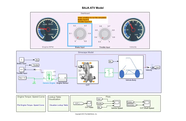
In this Simulink model Speed(rpm) gauge, Brake input, throttle input and velocity are connected to dash board.
While simulation is running (simulation time is "inf") we change break and throttle input manually by using knobs.
Similarly as previous input data is taken from workspace.
Analysis Results:-
- Vehicle speed
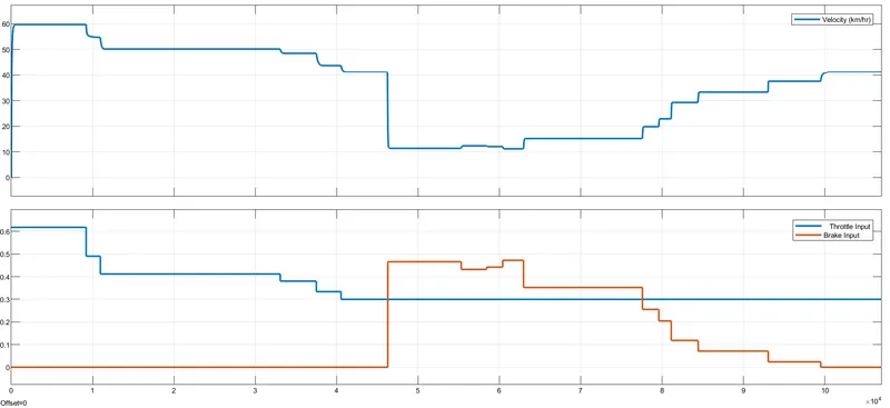
here we observe that velocity follows same path as the input (Throttle & brake)
- CVT shaft speed
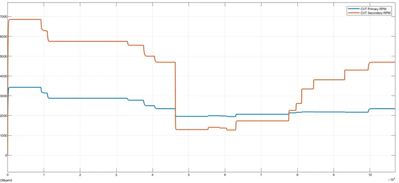
Here we observe that the primary pulley rpm is less than secondary pulley rpm
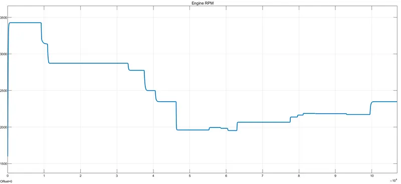
- Engine RPM
CONCLUSION:-
- we simulate BAJA All terrain vehicle with and without look up table, and the results are plotted.
- All results are satisfactory.
*************************************************************************************************************************************************************************************************************************************************************************************************************************************** END